EP1709933B1 - Pièce à main médicale avec axe formant un angle - Google Patents
Pièce à main médicale avec axe formant un angle Download PDFInfo
- Publication number
- EP1709933B1 EP1709933B1 EP06006455A EP06006455A EP1709933B1 EP 1709933 B1 EP1709933 B1 EP 1709933B1 EP 06006455 A EP06006455 A EP 06006455A EP 06006455 A EP06006455 A EP 06006455A EP 1709933 B1 EP1709933 B1 EP 1709933B1
- Authority
- EP
- European Patent Office
- Prior art keywords
- receiving sleeve
- shank
- shaft portion
- shaft
- sleeve
- Prior art date
- Legal status (The legal status is an assumption and is not a legal conclusion. Google has not performed a legal analysis and makes no representation as to the accuracy of the status listed.)
- Expired - Lifetime
Links
Images

Classifications
-
- A—HUMAN NECESSITIES
- A61—MEDICAL OR VETERINARY SCIENCE; HYGIENE
- A61C—DENTISTRY; APPARATUS OR METHODS FOR ORAL OR DENTAL HYGIENE
- A61C1/00—Dental machines for boring or cutting ; General features of dental machines or apparatus, e.g. hand-piece design
- A61C1/08—Machine parts specially adapted for dentistry
- A61C1/18—Flexible shafts; Clutches or the like; Bearings or lubricating arrangements; Drives or transmissions
- A61C1/185—Drives or transmissions
Definitions
- the invention relates to a medical handpiece according to the preamble of claim 1.
- the DE 32 27 417 A1 shows a dental dental handpiece with a shaft which is transversely divided in the region of the shaft angulation.
- the invention has for its object to improve the mountability in a handpiece of the type specified. In addition, a simple, cost e and small construction is sought.
- the embodiments of the invention is based on the finding that an assembly of the receiving sleeve from the back in the front shaft portion is favorable ig and thereby can realize an axial fixation of the receiving sleeve.
- the receiving sleeve from the rear into the front shaft portion can be screwed.
- a simple installation from behind but also a secure axial positioning of the receiving sleeve is possible because not only the axial positioning of the receiving sleeve is ensured by screwing, but also their introduction into their axial end position, in which they automatically when screwing .
- On the receiving sleeve rotary engagement elements are arranged at the rear end and accessible from behind. As a result, a screwing and unscrewing of the receiving sleeve is facilitated.
- the front shaft portion is arranged in the shaft so that its rear end is closer to the concave back side of the shaft formed by the angling of the two shaft portions, as on the convex ventral side thereof.
- the available in the front shaft portion Konstr tion space can thus be better utilized with respect to a favorable for the assembly of the front shaft portion position.
- the relevant design parameters of the handpiece are chosen such that the receiving sleeve passes through the opening at the end of the rearward shaft portion into the forward shaft portion can be inserted by means of a linear movement and anchored there.
- the receiving sleeve is also mountable or removable from behind, namely by a linear insertion or withdrawal movement.
- the hole edge of the opening is located on the rear shaft portion on the convex abdominal side of the shaft in a position in which it has a radial distance from the longitudinal center axis of the receiving hole in the front shaft portion and this radial distance corresponds to at least the largest radial dimension of the receiving sleeve, so that this is movable past the opening edge in its linear movement n.
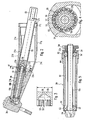
- FIG. 1 in its entirety designated 1 treatment instrument consists of a rear instrument part, namely a so-called. Anschlußtei 1 2, and a front instrument part, namely a so-called.
- Handpiece 3 which are releasably connected to each other by a plug-in coupling 4, in particular a plug / rotary coupling.
- a preferably releasable holding device 5 is arranged for a tool 6, which the tool 6 in holds a laterally projecting position.
- the holding device 5 forms a tool holder.
- the plug / rotary coupling is formed by a circular cross-section coupling recess 7 and a plug-in therein with little play coupling pin 8.
- the coupling recess 7 is arranged at the rear end of the handpiece 3, and the substantially cylindrical or stepped cylindrical coupling pin 8 extends from the connection part 2 to the front.
- the coupling recess 7 and the coupling pin 8 are releasably locked together by a latching device with a detent element 9 shown hinted, which is radially movably mounted in the one coupling part and biased by a spring force in a parting line between the coupling parts passing latching position in the the Verrastungselement 9 engages in an annular groove in the other coupling part.
- Such a known locking device can be overridden by a manual Switzerlandkraftausübung for separating the coupling parts, the latching element 9 is automatically displaced into its release position.
- the latching element 9 is z.
- the connector 2 is connected or connected in a manner not shown with a flexible supply line 2a, which is connected to a control unit.
- the handpiece 3 is in the presence of the plug / rotary coupling 360 ° freely rotatably mounted on the connector 2, whereby the handling of the handpiece 3 is improved.
- the holding device 5 has a receiving sleeve 12 for receiving the tool 6, which at the tool end has an accessible from the tool side insertion opening 12a for the tool 6 and its holding element.
- the receiving sleeve 12 is in a transverse, e.g. right- or obtuse-angled, to the longitudinal central axis 13a, 13b of the handpiece 3 extending position in a corresponding bearing assembly in the front end portion of the handpiece 3 movable, z. B. rotatable, stored.
- two pivot bearings 14a, 14b e.g. Rolling, arranged between the end bearing journals of the receiving sleeve 12 and the inner peripheral wall of a bearing bore 16.
- the receiving sleeve 12 and the holding device 5 can be moved by a drive 17 with a drive motor, not shown, in or outside of the Handpiece 3 may be arranged, for example in the connecting part 2.
- a drive shaft 18 which is in driving connection with the receiving sleeve 12 and the holding device 5.
- the handpiece 3 has an elongate shaft 21, at the front end of a handpiece head is arranged, in which the receiving sleeve 12 is rotatably mounted.
- the shaft 21 consists of a rear shaft portion 21a and a front shaft portion 21b, which enclose an obtuse angle W1 with each other, which is about 155 to 170 °, preferably about 160 to 165 °.
- the front shaft portion 21b is thus angularly offset with respect to the longitudinal axis 13a of the rear shaft portion 21a by an acute angle W2 of about 10 to 30 °, in particular about 15 to 20 °, to the side facing away from the insertion 12a.
- the shaft 21 on the side at which the insertion opening 12a is located, a convex abdominal side 21c and opposite a concave back side 21d.
- the bend or apex of curvature is designated 21 e.
- the front shaft portion 21b extends forward convergent to a thickened working head 3a of the handpiece 3.
- the longitudinal axis 12b or axis of rotation of the receiving sleeve 12 includes with the longitudinal center axis 13b of the front shaft portion 21b an angle W3, which may be 90 °, z. B. is greater than 90 °, preferably about 95 to 115 °, in particular about 105 ° or about 90 to 105 °. These angular sizes result in ensuring an advantageous grip position of the handpiece 3 gripping operating hand a space-favorable form with respect to a treatment site, especially in the oral cavity of a patient.
- the drive shaft 18 is made up of a rear shaft portion 18a rotatably supported in the rear shaft portion 21a and a front shaft portion 18b extending in the front shaft portion 21b and rotatably supported therein and rotatably coupled to each other in the region of the apex 21e.
- a gear train having a pinion gear 23a disposed on the front end of the rear drive shaft section 18a and a pinion gear 23b provided on the rear end of the front shaft section 18b is used.
- the front shaft portion 18b is offset to the concave back side 21d with respect to the longitudinal center axis 13b of the front shaft portion 21b and also the front end of the rear shaft portion 18a, so that the pinion 23b at the rear end of the front shaft portion 18b also moves forward with respect to the pinion gear 23b End of the rear shaft portion 18a to the concave back side 21 d is offset.
- the rotation axis 18d of the front shaft portion 18a is angularly offset with respect to the longitudinal center axis 13b of the front shaft portion 21b to the concave back side 21d so that the rotation axis 18d extends parallel to the longitudinal generatrix 21f of the front shaft portion 21b on the concave back side 21d.
- a pinion 24 is arranged, which meshes with a arranged on the receiving sleeve 12 and preferably integrally formed thereon pinion 25, which preferably meshes with the pinion 24 on its insertion opening 12a side facing away, on the basis of the angle W3 can realize a space-efficient gear train.
- the latter is preferably in each case a screw connection 31, 32, of which the rear receiving sleeve 28 is located in its central region and the front receiving sleeve 29 is in its rear end region. Both screw 31, 32 each have an external thread on the associated sleeve and an internal thread in the associated shaft portion.
- screw connections 31, 32 are each arranged in the region of a thickening 28a, 29a of the associated sleeve and in a cross-sectional widening in the associated shaft section. This results for each screw 31, 32 in a forward of her distance a shoulder surface stop 33, 34 for the associated receiving sleeve 28, 29, whereby this is axially accurately positioned in the bolted state and is also fixed against loosening.
- the rear shank portion 21 a consists of two longitudinal sections, namely a from the apex 21 e rearwardly only over a portion of the rear receiving sleeve 28 extending shaft sleeve portion 21 g and a rear arranged Schulfthggsenabêt 21 h, which extends to the rear end of the shaft 21 and the back with the also ends up to the rear end extending receiving sleeve 28.
- the front receiving sleeve portion 21g is thus shorter than the rearward shaft portion 21a.
- the rear shaft sleeve portion 21h thus sits on the rear end portion of the receiving sleeve 28, and it is pushed from behind on it and fixed by a fixing device against a return movement.
- the associated fixing device is formed by a latching device 35 with a latching recess on the one component and a latching projection engageable therein on the other component.
- the latching recess may be formed by an annular groove 35a in the lateral surface of the receiving sleeve 28 and the latching projection by an annular bead 35b on the inner circumferential surface of the rear shaft sleeve portion 21h.
- the latching device 35 can be pushed over by an axial force effect when pushing or pushing off the rear shaft sleeve section 21h, d. h.,
- the locking projection makes the axial movement a certain resistance, which is overcome by the axial force effect, both when snapped into the recess 35a as well as during disengagement.
- the latching recess 35 is preferably arranged at a short distance from the rear end of the shaft sleeve section 21h and the receiving sleeve 28.
- a detent device 35 surrounding annular groove 36 is arranged, which opens out to the rear and can improve the flexibility of the locking device 35.
- the rear shaft sleeve portion 21h is preferably made of plastic, whereby the flexibility is improved and also the locking device 35 benefits.
- the shaft sleeve portion 21h is made thicker than the rear shaft portion 21a at least in its rear end portion, and tapers forward to a sleeve thickness corresponding to the front shaft sleeve portion 21d, so that these two portions merge with their outer circumferential surfaces at the parting line.
- the handpiece is designated in its entirety by 37 feeding device for a gaseous or liquid medium, such.
- a gaseous or liquid medium such as air, water or an air / water mixture associated with a supply line 37 a, which extends longitudinally through the supply line 2 a, the connector 2 and through the coupling 4 to the front end portion of the handpiece 3 and is directed to the treatment site
- the supply pipe 37a except for the rear hand piece portion extends outside the hand piece 3, and is formed in this external portion by a hose 38 extending from a hose fitting 46 in the rear end portion of the hand piece 3 to the front end portion, and in the front Area is connected to a C-shaped clip 39 which is clipped transversely on the front shaft portion 21 b.
- the supply line 37a initially extends axially in the connection part 2 and in the coupling pin 8, in the region of which it opens radially, in a arranged between the coupling pin 8 and the receiving sleeve 28 annular groove 41, preferably in the Inner lateral surface of the receiving sleeve 28 is arranged. From the annular groove 41, the feed line 37a extends in the form of one or more circumferentially spaced holes 42 in an annular groove 43 between the receiving sleeve 28 and the rear shaft sleeve portion 21h, wherein the annular groove 43 is preferably disposed in the lateral surface of the receiving sleeve 28.
- a hole 44 extends in the rear shaft sleeve portion 21h to the outside, from which a channel 45 extends to the hose connection 46, in the embodiment by a preferably integrally formed on the shaft sleeve portion 21h and, for example, axially or obliquely forwardly extending hose nozzle 46a is formed, to which the hose 38 is attached and thus connected.
- the channel 44 preferably extends obliquely so that it can be drilled from the front end of the shaft sleeve section 21h (shown) or from the rear end (not shown).
- annular grooves 41, 43 are arranged between the coupling pin 8 and the receiving sleeve 28 and between this and the shaft sleeve portion 21h ring seals. These can be formed by arranged in annular grooves O-rings 47, 48.
- the annular grooves can be inner ring grooves in the shaft sleeve section 21h or in the receiving sleeve 28 (not shown) or outer annular grooves in the receiving sleeve 28 and in the coupling pin 8, as shown.
- the receiving sleeves 28, 29 each form with the shaft sections rotatably mounted therein and two axially spaced rolling bearings and the associated gears a vorfertigbare sleeve assembly that can be easily and quickly mounted or replaced for the initial assembly or exchange.
- a rotary tool 55 is positively connected.
- Fig. 2 shows a pin-shaped rotary tool 55 which is formed at its front end sleeve-shaped with a sleeve shape arranged in the cavity 56.
- the rotary tool 55 is adapted to engage over the pinion 23 b and to engage the rear rotary engagement elements 54 on the receiving sleeve 29.
- the rotary control elements 54 are preferably formed by teeth and tooth spaces arranged therebetween, which are distributed over the entire circumference of the receiving sleeve 29 and axially accessible from behind.
- the pinion 23b is so large that it obscures the accessibility of the rotary engagement members 54 from behind, it is with teeth and tooth spaces in the same number as the To form teeth and tooth gaps of the pinion 23b.
- the teeth 57 of the rotary tool 55 can be set through the tooth gaps of the pinion 23b in the tooth spaces of the rotary control elements 54 and thus positively connected with these: This configuration makes it possible in the confined spaces of a dental handpiece 3 despite a relatively large Embodiment of the pinion 23b to ensure accessibility to the rotary engagement elements 54 of the receiving sleeve 29.
- the prefabricated as an independent unit front receiving sleeve 29 consists of a sleeve body 61, the shaft portion 18b with the end arranged thereon pinions 24, 54 and two pivot bearings 52, in particular rolling bearings, which sit in the two end portions of the shaft portion 18b and in end bearing bores 62, 63 are each inserted from the associated sleeve body end forth and rest with their outer rings on the inside on a shoulder surface 64 of the bearing bores 62, 63, wherein the pinion 24, 54 abut the outer sides of the inner rings of the pivot bearing 52.
- the above-described parts of the receiving sleeve 29 are determined axially and radially, taking into account a required movement play.
- the receiving sleeve 29 thus forms a preassembled unit which can be inserted and screwed into the front shaft section 21b from the rear and can be fixed axially against the shoulder surface stop 34.
- the screwing in from behind is possible because in the rear shaft portion 21 a so much freedom is available that the receiving sleeve 29 as described above can be mounted.
- the rear edge 21 i of the opening 21 j of the receiving sleeve portion 21 g a distance a from an imaginary extension of the rotational and longitudinal central axis 18 d of the front shaft portion 18 b, which is so large that the receiving sleeve 29 in a coaxial movement from behind can be inserted and screwed in and removed again.
- the pinions 24, 25 between the front shaft portion 18b and the receiving sleeve 12 are engaged.
- the receiving sleeve 29 serve the rotary control elements 54 at the rear end of the sleeve body 61, which are accessible from the rear with the rod-shaped rotary tool 55, that at its rear end also a rotary control means 65, z.
- a hexagon has and is sized so long that it is accessible from the rear.
- the rotary tool 55 projects beyond the rear edge 21i with the rotary engagement means 65.
- the rotary tool 55 has approximately the same cross-sectional size as the Receiving sleeve 29, in particular in the region of the thickening 29a. Therefore, the rotary tool 55 can also be moved into the working position and rotated in a functional position in the case of a coaxial arrangement with respect to the axis of rotation 18d and a linear feed movement to the rotary control element 54.
- the cross-sectional dimension b of the rotary tool 55 in its front end portion is adapted to the outer diameter of the pinion 23 b in the present embodiment, in which the pinion 23 b covers the end face of the sleeve body 61 from the rear.
- the rotary engagement elements 53 on the rotary tool 55 are formed by teeth projecting from the front side thereof, which are adapted to the size of the tooth gaps of the pinion 23b so that they can be pushed through the gaps and reach between the rotary engagement elements 54 at the rear end of the sleeve body 61 , which are preferably formed to rearwardly projecting teeth, which are also formed so that the teeth of the rotary tool 55 between the teeth of the sleeve body 61 are pluggable.
- rear receiving sleeve 28 is also formed by a sleeve body 66 which is inserted from behind into the receiving hole 26 of the rear shaft portion 21 a and in the rear shaft portion 18 a in two pivot bearings 51 which are axially spaced from each other and in the front half of the Sleeve body 66 are arranged.
- the rear shaft portion 18a with the arranged at its front end pinion 23a is inserted with the roller bearings 51 from behind into the sleeve body 66 and axially fixed.
- the pinion 23a with respect to the pinion 23b in its correct axial combing position.
- rotary control elements 53 are provided at the rear end, which are accessible to a rotary tool, not shown, and z. B. are formed by opening out to the rear holes.
- the rear shoulder stop 33 for the rear receiving sleeve 28 in the rear shaft portion 21a and the front shoulder surface stop 34 for the front receiving sleeve 29 in the front shaft portion 21d are in longitudinal positions in the shaft 21, in which the pre-assembled receiving sleeves 28, 29 are arranged so that the rear Ritz pair 23a, 23b and the front pair of pinions 24, 25 in the correct combing positions are. An axial alignment of the receiving sleeves 28, 29 is therefore not required.
- the front shaft portion 18b is disposed in the front shaft portion 21b such that the rear end of the front shaft portion 18b is closer to the concave back side 21d of the shaft 21 formed by the angling of the two shaft portions 21a, 21 than to the convex belly side 21c.
- the rear end of the front shaft portion 18d and the front receiving sleeve 29 is thus angularly offset to the back side 21d with respect to known per se, in which the central or rotation axis 18d of the shaft portion 18b is coaxial with the longitudinal center axis 13b of the front shaft portion 21b.
- the axis of rotation 18d or the longitudinal center axis of the front shaft section 18b or of the front receiving sleeve 29 preferably extends parallel to the outside of the front shaft section 21b on the concave back side 21d.
- the axis of rotation 13a of the rear shaft portion 18a and the longitudinal center axis of the rear receiving sleeve 29 extends coaxially in the rear shaft portion 21 a, which extends at least in its front region with the same cross-sectional size.
- a position for the front pinion 23a of the rear shaft portion 18a which is offset toward the abdominal side 21c with respect to the rear pinion 23b of the front shaft portion 18b.
- the two pinions 23a, 23b thus mesh on the back side of the front pinion 23a and the ventral side of the rear pinion 23b of the shaft portions 18a, 18b.
- the existing interior space for the desired utilization of space can be exploited in that in the region of the Abwinklungsscheitels the receiving hole 26 extends into the rear end portion of the front shaft portion 21b and in the Abwinklungs Scheme a free space 23c for the meshing pinion 23a, 23b forms.
- the receiving hole 27 is extended rearwardly into the transition region of the rear shaft portion 21a. As a result, a clearance 27a is created, through which the rotary tool 55 can be pushed.
- a further design parameter is that the rear shaft portion 21 a can be shortened to a length L, in which the coaxial accessibility to the front shaft portion 18 b and the front receiving sleeve 29 is ensured. This shortening is done by dismantling the shaft sleeve section 21h and the rear receiving sleeve 28.
- the accessibility of not only the front shaft portion 18 b and the front receiving sleeve 29, but also the rotary tool 55 is ensured due to the distance a.
- the accessibility can thus also improve that the rear shaft portion 21b can be shortened, so that for the edge 21e on the ventral side 21c with respect to the flight with the front receiving sleeve 29 more favorable position results, in which the front receiving sleeve 29 or Rotary tool 55 by substantially coaxial moving from the rear mounted or disassembled or can be removed in functional position and removed from the functional position.
- the rear shaft portion 21 b can be extended again, which is done in the embodiment by the installation of the rear receiving sleeve 28.
- the extension of the rear shaft portion 21 a could be completed, wherein the rear shaft portion 21 a may extend to the rear end of the mounted rear receiving sleeve 28.
- the sleeve shank portion 21h is present, which is withdrawn for shortening and pushed back for extension.
- a quick-release connection which is formed in the embodiment by a latching connection 35 and a fast and easy to handle pulling off and pushing back the Hüllenschaftabitess 21h allows.
Landscapes
- Health & Medical Sciences (AREA)
- Oral & Maxillofacial Surgery (AREA)
- Dentistry (AREA)
- Epidemiology (AREA)
- Life Sciences & Earth Sciences (AREA)
- Animal Behavior & Ethology (AREA)
- General Health & Medical Sciences (AREA)
- Public Health (AREA)
- Veterinary Medicine (AREA)
- Dental Tools And Instruments Or Auxiliary Dental Instruments (AREA)
Claims (3)
- Pièce à main (3) médicale, en particulier dentaire,
dotée d'une tige (21) qui est constituée d'une section de tige avant et d'une section de tige arrière (21 a, 21 b), lesquelles forment entre elles un angle obtus (W1),
dotée d'une tête de travail (3a) au niveau de l'extrémité avant de la section de tige avant (21 b), laquelle section de tige se rétrécit en direction de la tête de travail (3a),
et dotée d'un arbre d'entraînement (18) dans la tige (21), qui est constitué d'une section d'arbre avant et d'une section d'arbre arrière (18a, 18b), lesquelles se trouvent en liaison d'entraînement entre elles,
sachant que la section d'arbre arrière (18a) s'étend dans la section de tige arrière (21a) et est logée à l'intérieur de celle-ci de manière à pouvoir tourner, et sachant que la section d'arbre avant (18b) s'étend dans la section de tige avant (21 b) et est logée dans cette dernière de manière à pouvoir tourner,
sachant que l'extrémité avant de la section d'arbre avant (18b) se trouve en liaison d'entraînement avec un porte-outil logé de manière à pouvoir être déplacé dans la tête de travail (3a),
et sachant que la section d'arbre avant (18b) est logée dans un manchon de réception (29),
caractérisée en ce
que le manchon de réception (29) peut être vissé depuis l'arrière dans la section de tige avant (21 b), et en ce que des éléments d'attaque rotatifs (54) sont disposés au niveau du manchon de réception (29) sur l'extrémité arrière et sont accessibles depuis l'arrière, auxquels un outil rotatif peut être relié par complémentarité de forme. - Pièce à main selon la revendication 1,
caractérisée en ce
que la section d'arbre avant (18b) est disposée de telle manière dans la tige (21) que son extrémité arrière se trouve plus à proximité du côté arrière (21d) de la tige (21) concave formé par le coudage des deux sections de tige (21 a, 21b) que du côté inférieur (21c) convexe. - Pièce à main selon la revendication 1 ou 2,
caractérisée en ce
que les paramètres de construction de la pièce à main (3) importants sont choisis de telle sorte que le manchon de réception (29) peut être inséré par coulissement par l'ouverture (21f) au niveau de l'extrémité de la section de tige arrière (21a), dans la section de tige avant (21b) au moyen d'un mouvement linéaire et y être ancré.
Applications Claiming Priority (1)
| Application Number | Priority Date | Filing Date | Title |
|---|---|---|---|
| DE102005016049A DE102005016049A1 (de) | 2005-04-07 | 2005-04-07 | Medizinisches Handstück mit einem abgewinkelten Schaft |
Publications (3)
| Publication Number | Publication Date |
|---|---|
| EP1709933A2 EP1709933A2 (fr) | 2006-10-11 |
| EP1709933A3 EP1709933A3 (fr) | 2006-11-08 |
| EP1709933B1 true EP1709933B1 (fr) | 2012-10-24 |
Family
ID=36586003
Family Applications (1)
| Application Number | Title | Priority Date | Filing Date |
|---|---|---|---|
| EP06006455A Expired - Lifetime EP1709933B1 (fr) | 2005-04-07 | 2006-03-28 | Pièce à main médicale avec axe formant un angle |
Country Status (3)
| Country | Link |
|---|---|
| US (1) | US7736146B2 (fr) |
| EP (1) | EP1709933B1 (fr) |
| DE (1) | DE102005016049A1 (fr) |
Families Citing this family (3)
| Publication number | Priority date | Publication date | Assignee | Title |
|---|---|---|---|---|
| EP3175816B1 (fr) * | 2013-03-04 | 2019-02-27 | W & H Dentalwerk Bürmoos GmbH | Contra-angle médical, en particulier dentaire |
| US9504478B2 (en) * | 2014-04-30 | 2016-11-29 | Gyrus ACMI , Inc. | Rotary tool with improved coupling assembly |
| JP7279912B2 (ja) * | 2018-10-05 | 2023-05-23 | 医療法人社団プレシャスワン | 歯間のスペースメイキング装置およびスペースメイキング方法 |
Family Cites Families (19)
| Publication number | Priority date | Publication date | Assignee | Title |
|---|---|---|---|---|
| US2010421A (en) * | 1933-05-23 | 1935-08-06 | Terry Walter John | Angular attachment for dental handpieces |
| US2025779A (en) * | 1934-02-16 | 1935-12-31 | Gustav A Roelke | Dental tool |
| US2923060A (en) * | 1957-01-08 | 1960-02-02 | Staunt Martin | Dental handpieces |
| DE1100876B (de) * | 1957-05-31 | 1961-03-02 | Ritter Co Inc | Zahnaerztliches Handstueck |
| GB1472586A (en) * | 1973-07-06 | 1977-05-04 | Kaltenbach & Voigt | Dental handpiece |
| DE2644458B2 (de) * | 1976-10-01 | 1981-06-25 | Kaltenbach & Voigt Gmbh & Co, 7950 Biberach | Zahnärztliches Handstück |
| DE2966994D1 (en) * | 1979-11-29 | 1984-06-20 | Siemens Ag | Dental handpiece assembly |
| ATE9543T1 (de) * | 1979-11-29 | 1984-10-15 | Siemens Aktiengesellschaft | Zahnaerztliche handstueckanordnung. |
| IT1151940B (it) | 1981-08-03 | 1986-12-24 | Micro Mega Sa | Dispositivo per prendere solidale il complesso di trasmissione nel corpo di un contrangolo da odontoiatria |
| DE8217760U1 (de) * | 1982-06-22 | 1982-10-14 | Gebrüder Wagschal GmbH & Co KG Feinmechanik, Feinoptik, Medizintechnik, 2804 Lilienthal | Eindrehinstrument zum eindrehen von zahnimplantaten |
| DE3433877C1 (de) * | 1984-09-14 | 1986-04-10 | Kaltenbach & Voigt Gmbh & Co, 7950 Biberach | Zahnaerztliches Handstueck |
| DE3507083A1 (de) * | 1985-02-28 | 1986-09-04 | Kaltenbach & Voigt Gmbh & Co, 7950 Biberach | Zahnaerztliches handstueck |
| DE4417810C2 (de) | 1994-05-20 | 1997-10-23 | Kaltenbach & Voigt | Ärztliches oder zahnärztliches Handstück |
| AU729347B2 (en) * | 1996-09-23 | 2001-02-01 | Professional Dental Technologies, Inc. | Dental prophylaxis angle and a pivotable prophy cup therefor |
| AT404550B (de) * | 1997-07-02 | 1998-12-28 | Rosenstatter Otto Dr | Zahnärztliches handstück |
| US6106287A (en) * | 1998-12-11 | 2000-08-22 | Yates; Davis | Filter system for coupling of a dental handpiece |
| DE10208692A1 (de) | 2001-08-28 | 2003-03-20 | Kaltenbach & Voigt | Medizinisches oder dentalmedizinisches Handstück mit einem in einem Wälzlager gelagerten Drehteil |
| ITBO20020617A1 (it) * | 2002-09-30 | 2004-04-01 | Castellini Spa | Manipolo odontoiatrico. |
| IL154561A0 (en) * | 2003-02-20 | 2003-09-17 | Yechiel Cohen | Dental screwdriver |
-
2005
- 2005-04-07 DE DE102005016049A patent/DE102005016049A1/de not_active Withdrawn
-
2006
- 2006-03-28 EP EP06006455A patent/EP1709933B1/fr not_active Expired - Lifetime
- 2006-04-05 US US11/399,094 patent/US7736146B2/en not_active Expired - Fee Related
Also Published As
| Publication number | Publication date |
|---|---|
| EP1709933A2 (fr) | 2006-10-11 |
| US20070264610A1 (en) | 2007-11-15 |
| EP1709933A3 (fr) | 2006-11-08 |
| US7736146B2 (en) | 2010-06-15 |
| DE102005016049A1 (de) | 2006-10-12 |
Similar Documents
| Publication | Publication Date | Title |
|---|---|---|
| DE7729110U1 (de) | Zahnärztliches Handstück | |
| EP1420712B1 (fr) | Piece a main medicale ou dentaire comprenant une partie rotative logee dans un palier a roulement | |
| EP1208809B1 (fr) | Piéce à main medicale ou dentaire comprenant au moins une partie tournante | |
| EP1900337B1 (fr) | Pièce à main médicale ou dentaire dotée d'une section arrière et avant | |
| EP0682921A2 (fr) | Pièce à main médicale ou dentaire | |
| EP1378207B1 (fr) | Pièce à main medicale ou dentaire avec un bouton-poussoir pour le désaccouplement d'un outil | |
| EP0029863B1 (fr) | Instrument à main dentaire | |
| EP2025300B1 (fr) | Pièce à main médicale ou dentaire | |
| EP1709933B1 (fr) | Pièce à main médicale avec axe formant un angle | |
| EP1234548B1 (fr) | Instrument de traitement médical ou dentaire avec un élément filtrant | |
| EP1709931B1 (fr) | Organe moteur, en particulier pièce à main dentaire avec un accouplement détachable pour un porte-outil | |
| EP2522297B1 (fr) | Instrument manuel dentaire doté d'une poignée longitudinale | |
| DE2653588C2 (de) | Zahnärztliches Handstück | |
| EP2124812B1 (fr) | Pièce à main médicale, en particulier médico-dentaire, comportant deux ouvertures de sortie distinctes pour des substances | |
| DE3036939A1 (de) | Zahnaerztliche handstueckanordnung | |
| EP0271597B1 (fr) | Soupape de retenue pour l'installation dans le conduit de fluide d'un appareil médical | |
| DE102019007592B4 (de) | Reinigungsvorrichtung zur Reinigung von Zahnzwischenräumen und Bürstenkopf für eine solche Reinigungsvorrichtung | |
| DE102004036454A1 (de) | Medizinisches, insbesondere dentalmedizinisches, Handstück mit einer Klemmhülse für ein Werkzeug | |
| EP2411680B1 (fr) | Vérin fluidique | |
| DE29823566U1 (de) | Handstück für ärztliche oder zahnärztliche Zwecke mit einer einstellbaren Anschlagvorrichtung | |
| DE102011018694A1 (de) | Wirbelsäulenimplantat und Werkzeug hierfür |
Legal Events
| Date | Code | Title | Description |
|---|---|---|---|
| PUAI | Public reference made under article 153(3) epc to a published international application that has entered the european phase |
Free format text: ORIGINAL CODE: 0009012 |
|
| PUAL | Search report despatched |
Free format text: ORIGINAL CODE: 0009013 |
|
| AK | Designated contracting states |
Kind code of ref document: A2 Designated state(s): AT BE BG CH CY CZ DE DK EE ES FI FR GB GR HU IE IS IT LI LT LU LV MC NL PL PT RO SE SI SK TR |
|
| AX | Request for extension of the european patent |
Extension state: AL BA HR MK YU |
|
| AK | Designated contracting states |
Kind code of ref document: A3 Designated state(s): AT BE BG CH CY CZ DE DK EE ES FI FR GB GR HU IE IS IT LI LT LU LV MC NL PL PT RO SE SI SK TR |
|
| AX | Request for extension of the european patent |
Extension state: AL BA HR MK YU |
|
| 17P | Request for examination filed |
Effective date: 20070412 |
|
| AKX | Designation fees paid |
Designated state(s): AT CH DE FR IT LI |
|
| 17Q | First examination report despatched |
Effective date: 20070622 |
|
| GRAP | Despatch of communication of intention to grant a patent |
Free format text: ORIGINAL CODE: EPIDOSNIGR1 |
|
| GRAS | Grant fee paid |
Free format text: ORIGINAL CODE: EPIDOSNIGR3 |
|
| GRAA | (expected) grant |
Free format text: ORIGINAL CODE: 0009210 |
|
| AK | Designated contracting states |
Kind code of ref document: B1 Designated state(s): AT CH DE FR IT LI |
|
| REG | Reference to a national code |
Ref country code: CH Ref legal event code: NV Representative=s name: BOHEST AG Ref country code: CH Ref legal event code: EP |
|
| REG | Reference to a national code |
Ref country code: AT Ref legal event code: REF Ref document number: 580475 Country of ref document: AT Kind code of ref document: T Effective date: 20121115 |
|
| REG | Reference to a national code |
Ref country code: DE Ref legal event code: R096 Ref document number: 502006012117 Country of ref document: DE Effective date: 20121220 |
|
| PG25 | Lapsed in a contracting state [announced via postgrant information from national office to epo] |
Ref country code: IT Free format text: LAPSE BECAUSE OF FAILURE TO SUBMIT A TRANSLATION OF THE DESCRIPTION OR TO PAY THE FEE WITHIN THE PRESCRIBED TIME-LIMIT Effective date: 20121024 |
|
| PLBE | No opposition filed within time limit |
Free format text: ORIGINAL CODE: 0009261 |
|
| STAA | Information on the status of an ep patent application or granted ep patent |
Free format text: STATUS: NO OPPOSITION FILED WITHIN TIME LIMIT |
|
| 26N | No opposition filed |
Effective date: 20130725 |
|
| REG | Reference to a national code |
Ref country code: DE Ref legal event code: R097 Ref document number: 502006012117 Country of ref document: DE Effective date: 20130725 |
|
| REG | Reference to a national code |
Ref country code: CH Ref legal event code: PCAR Free format text: NEW ADDRESS: HOLBEINSTRASSE 36-38, 4051 BASEL (CH) |
|
| REG | Reference to a national code |
Ref country code: FR Ref legal event code: PLFP Year of fee payment: 10 |
|
| PGFP | Annual fee paid to national office [announced via postgrant information from national office to epo] |
Ref country code: CH Payment date: 20150319 Year of fee payment: 10 |
|
| PGFP | Annual fee paid to national office [announced via postgrant information from national office to epo] |
Ref country code: FR Payment date: 20150319 Year of fee payment: 10 Ref country code: AT Payment date: 20150323 Year of fee payment: 10 |
|
| PGFP | Annual fee paid to national office [announced via postgrant information from national office to epo] |
Ref country code: DE Payment date: 20150330 Year of fee payment: 10 |
|
| REG | Reference to a national code |
Ref country code: DE Ref legal event code: R119 Ref document number: 502006012117 Country of ref document: DE |
|
| REG | Reference to a national code |
Ref country code: CH Ref legal event code: PL |
|
| REG | Reference to a national code |
Ref country code: AT Ref legal event code: MM01 Ref document number: 580475 Country of ref document: AT Kind code of ref document: T Effective date: 20160328 |
|
| REG | Reference to a national code |
Ref country code: FR Ref legal event code: ST Effective date: 20161130 |
|
| PG25 | Lapsed in a contracting state [announced via postgrant information from national office to epo] |
Ref country code: DE Free format text: LAPSE BECAUSE OF NON-PAYMENT OF DUE FEES Effective date: 20161001 Ref country code: LI Free format text: LAPSE BECAUSE OF NON-PAYMENT OF DUE FEES Effective date: 20160331 Ref country code: CH Free format text: LAPSE BECAUSE OF NON-PAYMENT OF DUE FEES Effective date: 20160331 Ref country code: FR Free format text: LAPSE BECAUSE OF NON-PAYMENT OF DUE FEES Effective date: 20160331 |
|
| PG25 | Lapsed in a contracting state [announced via postgrant information from national office to epo] |
Ref country code: AT Free format text: LAPSE BECAUSE OF NON-PAYMENT OF DUE FEES Effective date: 20160328 |