EP1710015B2 - Keramischer Wabenkörper - Google Patents
Keramischer Wabenkörper Download PDFInfo
- Publication number
- EP1710015B2 EP1710015B2 EP06007509.0A EP06007509A EP1710015B2 EP 1710015 B2 EP1710015 B2 EP 1710015B2 EP 06007509 A EP06007509 A EP 06007509A EP 1710015 B2 EP1710015 B2 EP 1710015B2
- Authority
- EP
- European Patent Office
- Prior art keywords
- honeycomb structure
- porous ceramic
- weight
- parts
- adhesive layer
- Prior art date
- Legal status (The legal status is an assumption and is not a legal conclusion. Google has not performed a legal analysis and makes no representation as to the accuracy of the status listed.)
- Expired - Lifetime
Links
Images


Classifications
-
- B—PERFORMING OPERATIONS; TRANSPORTING
- B01—PHYSICAL OR CHEMICAL PROCESSES OR APPARATUS IN GENERAL
- B01D—SEPARATION
- B01D39/00—Filtering material for liquid or gaseous fluids
- B01D39/14—Other self-supporting filtering material ; Other filtering material
- B01D39/20—Other self-supporting filtering material ; Other filtering material of inorganic material, e.g. asbestos paper, metallic filtering material of non-woven wires
- B01D39/2068—Other inorganic materials, e.g. ceramics
- B01D39/2093—Ceramic foam
-
- B—PERFORMING OPERATIONS; TRANSPORTING
- B01—PHYSICAL OR CHEMICAL PROCESSES OR APPARATUS IN GENERAL
- B01D—SEPARATION
- B01D46/00—Filters or filtering processes specially modified for separating dispersed particles from gases or vapours
- B01D46/24—Particle separators, e.g. dust precipitators, using rigid hollow filter bodies
- B01D46/2403—Particle separators, e.g. dust precipitators, using rigid hollow filter bodies characterised by the physical shape or structure of the filtering element
- B01D46/2418—Honeycomb filters
- B01D46/2425—Honeycomb filters characterized by parameters related to the physical properties of the honeycomb structure material
- B01D46/2448—Honeycomb filters characterized by parameters related to the physical properties of the honeycomb structure material of the adhesive layers, i.e. joints between segments
-
- B—PERFORMING OPERATIONS; TRANSPORTING
- B01—PHYSICAL OR CHEMICAL PROCESSES OR APPARATUS IN GENERAL
- B01D—SEPARATION
- B01D46/00—Filters or filtering processes specially modified for separating dispersed particles from gases or vapours
- B01D46/24—Particle separators, e.g. dust precipitators, using rigid hollow filter bodies
- B01D46/2403—Particle separators, e.g. dust precipitators, using rigid hollow filter bodies characterised by the physical shape or structure of the filtering element
- B01D46/2418—Honeycomb filters
- B01D46/2425—Honeycomb filters characterized by parameters related to the physical properties of the honeycomb structure material
-
- B—PERFORMING OPERATIONS; TRANSPORTING
- B01—PHYSICAL OR CHEMICAL PROCESSES OR APPARATUS IN GENERAL
- B01D—SEPARATION
- B01D46/00—Filters or filtering processes specially modified for separating dispersed particles from gases or vapours
- B01D46/24—Particle separators, e.g. dust precipitators, using rigid hollow filter bodies
- B01D46/2403—Particle separators, e.g. dust precipitators, using rigid hollow filter bodies characterised by the physical shape or structure of the filtering element
- B01D46/2418—Honeycomb filters
- B01D46/2425—Honeycomb filters characterized by parameters related to the physical properties of the honeycomb structure material
- B01D46/2429—Honeycomb filters characterized by parameters related to the physical properties of the honeycomb structure material of the honeycomb walls or cells
-
- B—PERFORMING OPERATIONS; TRANSPORTING
- B01—PHYSICAL OR CHEMICAL PROCESSES OR APPARATUS IN GENERAL
- B01D—SEPARATION
- B01D46/00—Filters or filtering processes specially modified for separating dispersed particles from gases or vapours
- B01D46/24—Particle separators, e.g. dust precipitators, using rigid hollow filter bodies
- B01D46/2403—Particle separators, e.g. dust precipitators, using rigid hollow filter bodies characterised by the physical shape or structure of the filtering element
- B01D46/2418—Honeycomb filters
- B01D46/2425—Honeycomb filters characterized by parameters related to the physical properties of the honeycomb structure material
- B01D46/24491—Porosity
-
- B—PERFORMING OPERATIONS; TRANSPORTING
- B01—PHYSICAL OR CHEMICAL PROCESSES OR APPARATUS IN GENERAL
- B01D—SEPARATION
- B01D46/00—Filters or filtering processes specially modified for separating dispersed particles from gases or vapours
- B01D46/24—Particle separators, e.g. dust precipitators, using rigid hollow filter bodies
- B01D46/2403—Particle separators, e.g. dust precipitators, using rigid hollow filter bodies characterised by the physical shape or structure of the filtering element
- B01D46/2418—Honeycomb filters
- B01D46/2425—Honeycomb filters characterized by parameters related to the physical properties of the honeycomb structure material
- B01D46/24492—Pore diameter
-
- B—PERFORMING OPERATIONS; TRANSPORTING
- B01—PHYSICAL OR CHEMICAL PROCESSES OR APPARATUS IN GENERAL
- B01D—SEPARATION
- B01D46/00—Filters or filtering processes specially modified for separating dispersed particles from gases or vapours
- B01D46/24—Particle separators, e.g. dust precipitators, using rigid hollow filter bodies
- B01D46/2403—Particle separators, e.g. dust precipitators, using rigid hollow filter bodies characterised by the physical shape or structure of the filtering element
- B01D46/2418—Honeycomb filters
- B01D46/2425—Honeycomb filters characterized by parameters related to the physical properties of the honeycomb structure material
- B01D46/24495—Young's modulus
-
- B—PERFORMING OPERATIONS; TRANSPORTING
- B01—PHYSICAL OR CHEMICAL PROCESSES OR APPARATUS IN GENERAL
- B01D—SEPARATION
- B01D46/00—Filters or filtering processes specially modified for separating dispersed particles from gases or vapours
- B01D46/24—Particle separators, e.g. dust precipitators, using rigid hollow filter bodies
- B01D46/2403—Particle separators, e.g. dust precipitators, using rigid hollow filter bodies characterised by the physical shape or structure of the filtering element
- B01D46/2418—Honeycomb filters
- B01D46/2451—Honeycomb filters characterized by the geometrical structure, shape, pattern or configuration or parameters related to the geometry of the structure
- B01D46/2459—Honeycomb filters characterized by the geometrical structure, shape, pattern or configuration or parameters related to the geometry of the structure of the plugs
-
- B—PERFORMING OPERATIONS; TRANSPORTING
- B01—PHYSICAL OR CHEMICAL PROCESSES OR APPARATUS IN GENERAL
- B01D—SEPARATION
- B01D46/00—Filters or filtering processes specially modified for separating dispersed particles from gases or vapours
- B01D46/24—Particle separators, e.g. dust precipitators, using rigid hollow filter bodies
- B01D46/2403—Particle separators, e.g. dust precipitators, using rigid hollow filter bodies characterised by the physical shape or structure of the filtering element
- B01D46/2418—Honeycomb filters
- B01D46/2451—Honeycomb filters characterized by the geometrical structure, shape, pattern or configuration or parameters related to the geometry of the structure
- B01D46/247—Honeycomb filters characterized by the geometrical structure, shape, pattern or configuration or parameters related to the geometry of the structure of the cells
-
- B—PERFORMING OPERATIONS; TRANSPORTING
- B01—PHYSICAL OR CHEMICAL PROCESSES OR APPARATUS IN GENERAL
- B01D—SEPARATION
- B01D46/00—Filters or filtering processes specially modified for separating dispersed particles from gases or vapours
- B01D46/24—Particle separators, e.g. dust precipitators, using rigid hollow filter bodies
- B01D46/2403—Particle separators, e.g. dust precipitators, using rigid hollow filter bodies characterised by the physical shape or structure of the filtering element
- B01D46/2418—Honeycomb filters
- B01D46/2451—Honeycomb filters characterized by the geometrical structure, shape, pattern or configuration or parameters related to the geometry of the structure
- B01D46/2474—Honeycomb filters characterized by the geometrical structure, shape, pattern or configuration or parameters related to the geometry of the structure of the walls along the length of the honeycomb
-
- B—PERFORMING OPERATIONS; TRANSPORTING
- B01—PHYSICAL OR CHEMICAL PROCESSES OR APPARATUS IN GENERAL
- B01D—SEPARATION
- B01D46/00—Filters or filtering processes specially modified for separating dispersed particles from gases or vapours
- B01D46/24—Particle separators, e.g. dust precipitators, using rigid hollow filter bodies
- B01D46/2403—Particle separators, e.g. dust precipitators, using rigid hollow filter bodies characterised by the physical shape or structure of the filtering element
- B01D46/2418—Honeycomb filters
- B01D46/2498—The honeycomb filter being defined by mathematical relationships
-
- B—PERFORMING OPERATIONS; TRANSPORTING
- B01—PHYSICAL OR CHEMICAL PROCESSES OR APPARATUS IN GENERAL
- B01D—SEPARATION
- B01D53/00—Separation of gases or vapours; Recovering vapours of volatile solvents from gases; Chemical or biological purification of waste gases, e.g. engine exhaust gases, smoke, fumes, flue gases, aerosols
- B01D53/34—Chemical or biological purification of waste gases
- B01D53/74—General processes for purification of waste gases; Apparatus or devices specially adapted therefor
- B01D53/86—Catalytic processes
- B01D53/88—Handling or mounting catalysts
- B01D53/885—Devices in general for catalytic purification of waste gases
-
- B—PERFORMING OPERATIONS; TRANSPORTING
- B01—PHYSICAL OR CHEMICAL PROCESSES OR APPARATUS IN GENERAL
- B01J—CHEMICAL OR PHYSICAL PROCESSES, e.g. CATALYSIS OR COLLOID CHEMISTRY; THEIR RELEVANT APPARATUS
- B01J35/00—Catalysts, in general, characterised by their form or physical properties
- B01J35/50—Catalysts, in general, characterised by their form or physical properties characterised by their shape or configuration
- B01J35/56—Foraminous structures having flow-through passages or channels, e.g. grids or three-dimensional [3D] monoliths
- B01J35/57—Honeycombs
-
- F—MECHANICAL ENGINEERING; LIGHTING; HEATING; WEAPONS; BLASTING
- F01—MACHINES OR ENGINES IN GENERAL; ENGINE PLANTS IN GENERAL; STEAM ENGINES
- F01N—GAS-FLOW SILENCERS OR EXHAUST APPARATUS FOR MACHINES OR ENGINES IN GENERAL; GAS-FLOW SILENCERS OR EXHAUST APPARATUS FOR INTERNAL-COMBUSTION ENGINES
- F01N3/00—Exhaust or silencing apparatus having means for purifying, rendering innocuous, or otherwise treating exhaust
- F01N3/02—Exhaust or silencing apparatus having means for purifying, rendering innocuous, or otherwise treating exhaust for cooling, or for removing solid constituents of, exhaust
- F01N3/021—Exhaust or silencing apparatus having means for purifying, rendering innocuous, or otherwise treating exhaust for cooling, or for removing solid constituents of, exhaust by means of filters
- F01N3/022—Exhaust or silencing apparatus having means for purifying, rendering innocuous, or otherwise treating exhaust for cooling, or for removing solid constituents of, exhaust by means of filters characterised by specially adapted filtering structure, e.g. honeycomb, mesh or fibrous
- F01N3/0222—Exhaust or silencing apparatus having means for purifying, rendering innocuous, or otherwise treating exhaust for cooling, or for removing solid constituents of, exhaust by means of filters characterised by specially adapted filtering structure, e.g. honeycomb, mesh or fibrous the structure being monolithic, e.g. honeycombs
-
- F—MECHANICAL ENGINEERING; LIGHTING; HEATING; WEAPONS; BLASTING
- F01—MACHINES OR ENGINES IN GENERAL; ENGINE PLANTS IN GENERAL; STEAM ENGINES
- F01N—GAS-FLOW SILENCERS OR EXHAUST APPARATUS FOR MACHINES OR ENGINES IN GENERAL; GAS-FLOW SILENCERS OR EXHAUST APPARATUS FOR INTERNAL-COMBUSTION ENGINES
- F01N3/00—Exhaust or silencing apparatus having means for purifying, rendering innocuous, or otherwise treating exhaust
- F01N3/02—Exhaust or silencing apparatus having means for purifying, rendering innocuous, or otherwise treating exhaust for cooling, or for removing solid constituents of, exhaust
- F01N3/021—Exhaust or silencing apparatus having means for purifying, rendering innocuous, or otherwise treating exhaust for cooling, or for removing solid constituents of, exhaust by means of filters
- F01N3/033—Exhaust or silencing apparatus having means for purifying, rendering innocuous, or otherwise treating exhaust for cooling, or for removing solid constituents of, exhaust by means of filters in combination with other devices
- F01N3/035—Exhaust or silencing apparatus having means for purifying, rendering innocuous, or otherwise treating exhaust for cooling, or for removing solid constituents of, exhaust by means of filters in combination with other devices with catalytic reactors
-
- B—PERFORMING OPERATIONS; TRANSPORTING
- B01—PHYSICAL OR CHEMICAL PROCESSES OR APPARATUS IN GENERAL
- B01D—SEPARATION
- B01D2255/00—Catalysts
- B01D2255/10—Noble metals or compounds thereof
-
- B—PERFORMING OPERATIONS; TRANSPORTING
- B01—PHYSICAL OR CHEMICAL PROCESSES OR APPARATUS IN GENERAL
- B01D—SEPARATION
- B01D2255/00—Catalysts
- B01D2255/20—Metals or compounds thereof
- B01D2255/202—Alkali metals
-
- B—PERFORMING OPERATIONS; TRANSPORTING
- B01—PHYSICAL OR CHEMICAL PROCESSES OR APPARATUS IN GENERAL
- B01D—SEPARATION
- B01D2255/00—Catalysts
- B01D2255/20—Metals or compounds thereof
- B01D2255/204—Alkaline earth metals
-
- B—PERFORMING OPERATIONS; TRANSPORTING
- B01—PHYSICAL OR CHEMICAL PROCESSES OR APPARATUS IN GENERAL
- B01D—SEPARATION
- B01D2255/00—Catalysts
- B01D2255/20—Metals or compounds thereof
- B01D2255/206—Rare earth metals
-
- B—PERFORMING OPERATIONS; TRANSPORTING
- B01—PHYSICAL OR CHEMICAL PROCESSES OR APPARATUS IN GENERAL
- B01D—SEPARATION
- B01D2255/00—Catalysts
- B01D2255/20—Metals or compounds thereof
- B01D2255/207—Transition metals
-
- B—PERFORMING OPERATIONS; TRANSPORTING
- B01—PHYSICAL OR CHEMICAL PROCESSES OR APPARATUS IN GENERAL
- B01J—CHEMICAL OR PHYSICAL PROCESSES, e.g. CATALYSIS OR COLLOID CHEMISTRY; THEIR RELEVANT APPARATUS
- B01J23/00—Catalysts comprising metals or metal oxides or hydroxides, not provided for in group B01J21/00
- B01J23/38—Catalysts comprising metals or metal oxides or hydroxides, not provided for in group B01J21/00 of noble metals
- B01J23/40—Catalysts comprising metals or metal oxides or hydroxides, not provided for in group B01J21/00 of noble metals of the platinum group metals
- B01J23/42—Platinum
-
- B—PERFORMING OPERATIONS; TRANSPORTING
- B01—PHYSICAL OR CHEMICAL PROCESSES OR APPARATUS IN GENERAL
- B01J—CHEMICAL OR PHYSICAL PROCESSES, e.g. CATALYSIS OR COLLOID CHEMISTRY; THEIR RELEVANT APPARATUS
- B01J37/00—Processes, in general, for preparing catalysts; Processes, in general, for activation of catalysts
- B01J37/02—Impregnation, coating or precipitation
- B01J37/0215—Coating
-
- F—MECHANICAL ENGINEERING; LIGHTING; HEATING; WEAPONS; BLASTING
- F01—MACHINES OR ENGINES IN GENERAL; ENGINE PLANTS IN GENERAL; STEAM ENGINES
- F01N—GAS-FLOW SILENCERS OR EXHAUST APPARATUS FOR MACHINES OR ENGINES IN GENERAL; GAS-FLOW SILENCERS OR EXHAUST APPARATUS FOR INTERNAL-COMBUSTION ENGINES
- F01N2330/00—Structure of catalyst support or particle filter
- F01N2330/06—Ceramic, e.g. monoliths
-
- F—MECHANICAL ENGINEERING; LIGHTING; HEATING; WEAPONS; BLASTING
- F01—MACHINES OR ENGINES IN GENERAL; ENGINE PLANTS IN GENERAL; STEAM ENGINES
- F01N—GAS-FLOW SILENCERS OR EXHAUST APPARATUS FOR MACHINES OR ENGINES IN GENERAL; GAS-FLOW SILENCERS OR EXHAUST APPARATUS FOR INTERNAL-COMBUSTION ENGINES
- F01N2450/00—Methods or apparatus for fitting, inserting or repairing different elements
- F01N2450/28—Methods or apparatus for fitting, inserting or repairing different elements by using adhesive material, e.g. cement
-
- Y—GENERAL TAGGING OF NEW TECHNOLOGICAL DEVELOPMENTS; GENERAL TAGGING OF CROSS-SECTIONAL TECHNOLOGIES SPANNING OVER SEVERAL SECTIONS OF THE IPC; TECHNICAL SUBJECTS COVERED BY FORMER USPC CROSS-REFERENCE ART COLLECTIONS [XRACs] AND DIGESTS
- Y10—TECHNICAL SUBJECTS COVERED BY FORMER USPC
- Y10S—TECHNICAL SUBJECTS COVERED BY FORMER USPC CROSS-REFERENCE ART COLLECTIONS [XRACs] AND DIGESTS
- Y10S264/00—Plastic and nonmetallic article shaping or treating: processes
- Y10S264/48—Processes of making filters
-
- Y—GENERAL TAGGING OF NEW TECHNOLOGICAL DEVELOPMENTS; GENERAL TAGGING OF CROSS-SECTIONAL TECHNOLOGIES SPANNING OVER SEVERAL SECTIONS OF THE IPC; TECHNICAL SUBJECTS COVERED BY FORMER USPC CROSS-REFERENCE ART COLLECTIONS [XRACs] AND DIGESTS
- Y10—TECHNICAL SUBJECTS COVERED BY FORMER USPC
- Y10S—TECHNICAL SUBJECTS COVERED BY FORMER USPC CROSS-REFERENCE ART COLLECTIONS [XRACs] AND DIGESTS
- Y10S55/00—Gas separation
- Y10S55/05—Methods of making filter
-
- Y—GENERAL TAGGING OF NEW TECHNOLOGICAL DEVELOPMENTS; GENERAL TAGGING OF CROSS-SECTIONAL TECHNOLOGIES SPANNING OVER SEVERAL SECTIONS OF THE IPC; TECHNICAL SUBJECTS COVERED BY FORMER USPC CROSS-REFERENCE ART COLLECTIONS [XRACs] AND DIGESTS
- Y10—TECHNICAL SUBJECTS COVERED BY FORMER USPC
- Y10S—TECHNICAL SUBJECTS COVERED BY FORMER USPC CROSS-REFERENCE ART COLLECTIONS [XRACs] AND DIGESTS
- Y10S55/00—Gas separation
- Y10S55/10—Residue burned
-
- Y—GENERAL TAGGING OF NEW TECHNOLOGICAL DEVELOPMENTS; GENERAL TAGGING OF CROSS-SECTIONAL TECHNOLOGIES SPANNING OVER SEVERAL SECTIONS OF THE IPC; TECHNICAL SUBJECTS COVERED BY FORMER USPC CROSS-REFERENCE ART COLLECTIONS [XRACs] AND DIGESTS
- Y10—TECHNICAL SUBJECTS COVERED BY FORMER USPC
- Y10S—TECHNICAL SUBJECTS COVERED BY FORMER USPC CROSS-REFERENCE ART COLLECTIONS [XRACs] AND DIGESTS
- Y10S55/00—Gas separation
- Y10S55/30—Exhaust treatment
-
- Y—GENERAL TAGGING OF NEW TECHNOLOGICAL DEVELOPMENTS; GENERAL TAGGING OF CROSS-SECTIONAL TECHNOLOGIES SPANNING OVER SEVERAL SECTIONS OF THE IPC; TECHNICAL SUBJECTS COVERED BY FORMER USPC CROSS-REFERENCE ART COLLECTIONS [XRACs] AND DIGESTS
- Y10—TECHNICAL SUBJECTS COVERED BY FORMER USPC
- Y10T—TECHNICAL SUBJECTS COVERED BY FORMER US CLASSIFICATION
- Y10T428/00—Stock material or miscellaneous articles
- Y10T428/24—Structurally defined web or sheet [e.g., overall dimension, etc.]
- Y10T428/24149—Honeycomb-like
Definitions
- the present invention relates to a honeycomb structure serving as a filter for collecting and removing particulates etc. in exhaust gas discharged from an internal combustion engine such as a diesel engine.
- a honeycomb structure in the background art, for example, there has been disclosed a honeycomb structure comprising two or more honeycomb segments and a bonding layer for bonding these segments with each other, wherein the Young's modulus of the bonding layer is not higher than 20% of the Young's modulus of the honeycomb segments or the material strength of the bonding layer is lower than the material strength of the honeycomb segments (for example, see JP 2001-190916 A , EP1249262 A1 , EP1247556 A1 , EP1419816 A1 , EP 1479881 A1 ).
- EP 1479882 A1 discloses a honeycomb filter for purifying exhaust gases, which makes it possible to alleviate a thermal stress generated due to occurrence of a local temperature change, is less likely to generate cracks, and is excellent in strength and durability.
- Said document provides a honeycomb filter for purifying exhaust gases having a structure in that a plurality of column-shaped porous ceramic members, each having a number of through holes that are placed side by side in the length direction with partition wall interposed therebetween, are combined with one another through adhesive layers so that the partition wall that separates the through holes are allowed to function as a filter for collecting particulates, wherein the relationship between a thermal expansion coefficient alpha L of the adhesive layer and a thermal expansion coefficient alpha F of the porous ceramic member is as follows: 0.01 ⁇ (alpha L - alpha F) / alpha F ⁇ 1.0.
- a filter for collecting particulates in exhaust gas and for converting gas components such as CO, HC, etc. of the exhaust gas by means of a catalyst is required to have a high exhaust gas converting rate in a comparatively early stage after the start of an engine. To this end, it has been believed that the heat capacity of the honeycomb structure has to be reduced.
- Means for providing a high porosity to the honeycomb structure and means for reducing the thickness of the cell walls of the honeycomb structure have been proposed as means for reducing the heat capacity of the honeycomb structure.
- the strength of the honeycomb structure may be lowered. This lowering of the strength also causes a crack in the honeycomb structure.
- the present inventor was intent on researches to solve the foregoing problems. As a result, the inventor newly discovered that a crack could be prevented in a honeycomb structure regardless of porosity or thickness of cell walls if a predetermined relationship was satisfied between the apparent density of porous ceramic members forming the honeycomb structure and the Young's modulus of an adhesive layer for bonding the porous ceramic members with each other. Thus, the inventor brought the invention to completion.
- a honeycomb structure is one in which a plurality of porous ceramic members are bonded through an adhesive layer, each of the porous ceramic members having a plurality of cells, which are arranged in parallel while being separated by cell walls, and the cells extends in a longitudinal direction of the honeycomb structure.
- the apparent density (of the porous ceramic members) is 0.55 g/cm 3 .
- a catalyst is carried and supported in at least a part of the cell walls.
- the apparent density of the porous ceramic members and the Young's modulus of the adhesive layer satisfy specific values as defined in claim 1.
- the thermal stress generated in the honeycomb structure can be relaxed sufficiently by the adhesive layer, so that a failure such as a crack can be prevented from occurring in the honeycomb structure or the adhesive layer.
- the honeycomb structure according to the invention is suitable particularly to solve the problems belonging to the honeycomb structure having high porosity and thinned cell walls, which honeycomb structure has been regarded as easy to produce a failure such as a crack in the background art.
- a honeycomb structure according to the invention is one in which a plurality of porous ceramic members are bonded through an adhesive layer, each of the porous ceramic members having a plurality of cells, which are arranged in parallel while being separated by cell walls, and the cells extends in a longitudinal direction of the honeycomb structure.
- the thermal stress generated in the porous ceramic members can be relaxed so that a failure such as a crack can be prevented from occurring.
- the Young's modulus (GPa) of the adhesive layer is lower than 2 GPa, the strength of the adhesive layer itself will be so insufficient so that a crack may occur in the adhesive layer or a failure of the honeycomb structure may begin at a portion of the adhesive layer.
- the value A (g/cm3) designates the apparent density of the porous ceramic members.
- the true density in this specification designates density owned by the material of the porous ceramic members, and the apparent density designates density calculated based on the volume occupied by the external appearance of the porous ceramic members (for example, the volume of the square pillar shape in Fig. 2A ). If the honeycomb structure has high porosity or thin cell walls, the apparent density of the honeycomb structure will be reduced when the other conditions including the cell density are fixed.
- open area ratio is well known to one skilled in the art, and is defined as a ratio of a sum of areas of openings defined in an end surface of a honeycomb structure to a whole area of the end surface in plan view of the end surface as for instance described in " Glossary of Technical Terms in Japanese Industrial Standards (5th Edition)” (Japanese Standards Association (2001 )).
- the "open area ratio" of the porous ceramic member can be for instance measured in the following manner. At first, dimensions of openings defined in an end surface of a honeycomb structure and a dimension of the end surface of the honeycomb structure are measured with, for example, a slide gauge or a length-measurement microscopy. Then, the areas of the openings and the whole area of the end surface are calculated from the measured dimension. Finally, the open area ratio can be obtained from (i) a sum of the calculated area of the openings and (ii) the calculated whole area of the end surface.
- the value of the apparent density is 0.55 g/cm 3 .
- a plurality of porous ceramic members in each of which a plurality cells are arranged in parallel while being separated by cell walls and extend in the longitudinal direction are bonded with each other through an adhesive layer. It is desired that each of the plurality of cells is sealed up at one of the end portions thereof.
- honeycomb structure according to the invention will be described below with reference to the drawings. Description will be made below on the honeycomb structure in which each of the plurality of cells is sealed up at one of the end portions thereof.
- Fig. 1 is a perspective view schematically showing an embodiment of the honeycomb structure according to the invention.
- Fig. 2A is a perspective view of each porous ceramic member forming the honeycomb structure shown in Fig. 1 .
- Fig. 2B is a sectional view of the porous ceramic member, taken on line A-A in Fig. 2A .
- a honeycomb structure 10 in a honeycomb structure 10 according to the invention, a plurality of porous ceramic members 20 made of silicon carbide or the like are combined through an adhesive layer 11 so as to form a cylindrical ceramic block 15. A coating layer 12 is formed around the ceramic block 15.
- the ceramic block has a cylindrical shape.
- each porous ceramic member 20 As shown in Figs. 2A and 2B , a large number of cells 21 are arranged in parallel to extend in the longitudinal direction, and cell walls (wall portions) 23 separating the cells 21 from one another serve as a filter. That is, each cell 21 formed in the porous ceramic member 20 is sealed up with a plug 22 in its one end portion on the entrance side or the exit side of exhaust gas, as shown in Fig. 2B .
- the exhaust gas flowing into one cell 21 can only flow out from another cell 21 after passing through the cell wall 23 separating the cells 21 from each other.
- the apparent density of the porous ceramic members 20 and the Young's modulus of the adhesive layer 11 are as defined in claim 1. Accordingly, in the honeycomb structure 10, the thermal stress generated in the porous ceramic members 20 can be relaxed by the adhesive layer 11 so that a failure such as a crack can be prevented from occurring in the porous ceramic members.
- the honeycomb structure 10 is chiefly made of porous silicon carbide ceramics.
- silicon carbide based ceramics having a high heat resistance, superior mechanical characteristic and high thermal conductivity are used.
- the silicon carbide based ceramics designates ceramics containing at least 60 wt% of silicon carbide.
- the average pore size of the honeycomb structure is 11 ⁇ m.
- the porosity of the honeycomb structure is 45%.
- the porosity can be measured by a method known in the background art, for example, by a mercury intrusion method, an Archimedean method, a method using a scanning electron microscope (SEM), or the like.
- the open area ratio of the honeycomb structure (porous ceramic members) is 68.8%.
- the thickness of the cell walls is 0.25 mm.
- each porous ceramic member 20 is made of one and the same porous ceramics. Consequently, the adhesion strength between the plug 22 and the cell walls 23 can be enhanced.
- the coefficient of thermal expansion of the plug 22 can be matched with that of the cell walls 23 so as to prevent a gap from being produced between the plug 22 and the cell walls 23 or a crack from being produced in the plug 22 or portions of the cell walls 23 abutting against the plug 22 due to thermal stress at the time of manufacturing or using the honeycomb structure.
- the cell walls designate both the cell walls separating the cells 21 from one another and the outer circumferential portion of each porous ceramic member 20.
- the thickness of the plug 22 is not limited especially.
- a preferable lower limit is 1 mm, and a preferable upper limit is 20 mm.
- a more preferable lower limit is 3 mm, and a more preferable upper limit is 10 mm.
- the adhesive layer 11 has the aforementioned function of relaxing the thermal stress.
- the adhesive layer 11 is formed between the porous ceramic members 20 so as to serve as an adhesive for binding the plurality of porous ceramic members 20 with each another.
- the adhesive layer 11 also has a function of preventing the exhaust gas from leaking.
- the material forming the adhesive layer 11 is defined in claim 1 and can be used since the Young's modulus of the material which has been solidified satisfies a specific value as defined in claim 1.
- the material is made of an inorganic binder, an organic binder and inorganic fibers and inorganic particles.
- the inorganic binder is silica sol.
- the organic binder is carboxymethyl cellulose.
- the inorganic fibers are silica-alumina fibers.
- the inorganic particles are silicon carbide particles having high thermal conductivity.
- the coating layer 12 is formed on the outer circumferential surface of the ceramic block 15.
- the coating layer 12 serves as a sealant for preventing the exhaust gas from leaking out from the outer circumferential surface of the ceramic block 15, and as a reinforcement for shaping or reinforcing the honeycomb structure when the honeycomb structure 10 is installed in an exhaust passageway of an internal combustion engine.
- a material similar to that for forming the adhesive layer 11 is used as the material for forming the coating layer 12.
- the adhesive layer 11 and the coating layer 12 are made of one and the same material. Further, when the adhesive layer 11 and the coating layer 12 are made of one and the same material, the material of the adhesive layer 11 and the material of the coating layer 12 have one and the same compounding ratio.
- a catalyst may be carried and supported by at least parts of the cell walls in the honeycomb structure according to the invention.
- the honeycomb structure according to the invention has the cell walls carrying and supporting a catalyst capable of converting harmful gas components such as CO, HC, NOx, etc. of the exhaust gas , the harmful gas components of the exhaust gas can be converted sufficiently due to the catalytic reaction.
- the honeycomb structure according to the invention can improve the performance to purify the exhaust gas, and can further reduce the energy for burning the particulates.
- the catalyst is not limited especially.
- the catalyst may be a catalyst made of noble metal such as platinum, palladium or rhodium.
- a compound to be carried and supported may include alkali metals (Group I of the periodic table of the elements), alkaline-earth metals (Group II of the periodic table of the elements), rare-earth elements (Group III of the periodic table of the elements), transition metal elements, etc. in addition to the noble metals.
- the catalyst may be attached to the honeycomb structure after the surface of the honeycomb structure is coated with a catalyst support layer of alumina or the like in advance.
- the catalyst support layer may include oxide ceramics such as alumina, titania, zirconia, silica, etc.
- honeycomb structure carrying and supporting the aforementioned catalyst serves as a gas purifier similar to a DPF (Diesel Particulate Filter) with a catalyst known in the background art. Therefore, detailed description about the case where the honeycomb structure according to the invention also serves as a catalyst carrier will be omitted here.
- DPF Diesel Particulate Filter
- raw material paste having the aforementioned ceramics as its main component is extruded.
- square pillar-shaped ceramic molded bodies are produced.
- the raw material paste is limited to the one defined in claim 1.
- the raw material paste can attain 45% of porosity in the honeycomb structure which has been manufactured.
- the raw material paste is obtained by adding a binder, dispersion medium liquid, etc. to powder made of the aforementioned ceramics.
- the particle size of the ceramic powder is limited as defined in claim 1. It is preferable that the ceramic powder has low contraction in a subsequent firing process.
- the pore size etc. of the porous ceramic members can be adjusted by adjusting the firing temperature and the particle size of the ceramic powder.
- the ceramic powder may be subjected to oxidation treatment in advance.
- the binder is carboxymethyl cellulose.
- the dispersion medium liquid is water.
- a proper quantity of the dispersion medium liquid is mixed so that the viscosity of the raw material paste is within a predetermined range.
- This ceramic powder, binder and dispersion medium liquid are mixed by ATTRITOR or the like, kneaded sufficiently by a kneader or the like, and then extruded.
- a molding assistant may be added to the raw material paste in accordance with necessity.
- the molding assistant is not limited especially.
- Examples of the molding assistant may include ethylene glycol, dextrin, fatty acid, fatty acid soap, polyvinyl alcohol, etc.
- the ceramic molded body is dried by use of a microwave dryer, a hot air dryer, an oven, a dielectric dryer, a decompression dryer, a vacuum dryer, a freeze dryer, etc. so as to be formed into a ceramic dried body.
- a predetermined amount of plug paste which will serve as a plug is charged into each exit-side end portion of the entrance-side cell group and each entrance-side end portion of the exit-side cell group.
- the cells are clogged and sealed up.
- the plug paste is not limited especially. It is desired that the porosity of the plug produced in a subsequent process will be 30-75%. A paste similar to the aforementioned raw material paste is used.
- the ceramic dried body plugged with the plug paste is degreased at 400 °C) and fired at 2,200 °C).
- a porous ceramic member 20 made of porous ceramics and formed into a single sinter as a whole is formed into a porous ceramic member 20 made of porous ceramics and formed into a single sinter as a whole.
- the conditions used for manufacturing a filter made of porous ceramics in the background art can be applied to the conditions with which the ceramic dried body is degreased and fired.
- porous ceramic member 20 which will serve as the adhesive layer 11 is applied to the side surface of the porous ceramic member 20 so as to form an adhesive paste layer.
- Another porous ceramic member 20 is laminated onto the adhesive paste layer. This process is repeated to produce a porous ceramic member assembly having predetermined dimensions.
- the material forming the adhesive paste has been already described in detail. Therefore, the description of the material will be omitted here. It is necessary to select the material in consideration of the apparent density of the porous ceramic members 20 and the Young's modulus of the adhesive layer to be formed.
- the porous ceramic member assembly is heated.
- the adhesive paste layer is dried and solidified to form the adhesive layer 11.
- porous ceramic member assembly in which a plurality of porous ceramic members 20 have been bonded through the adhesive layer 11 is cut by a diamond cutter so as to produce the cylindrical ceramic block 15.
- the coating layer 12 is formed out of the aforementioned coating paste on the outer circumference of the ceramic block 15.
- the honeycomb structure 10 in which the coating layer 12 is provided in the outer circumferential portion of the columnar ceramic block 15 having a plurality of porous ceramic members 20 bonded through the adhesive layer 11.
- a catalyst is carried and supported by the honeycomb structure (cell walls) in accordance with necessity.
- the catalyst may be carried and supported on the porous ceramic members which have not yet been formed into an assembly.
- an alumina coat (film) having a large specific surface area may be formed on the surfaces of the cell walls, and a promoter and the catalyst such as platinum may be given to the surface of the alumina coat (film).
- the honeycomb structure according to this exemplary embodiment is premised on that the apparent density A of the porous ceramic member 20 is measured before the catalyst support layer and/or the catalyst are applied to the honeycomb structure. Process of applying the catalyst support layer and/or the catalyst to a honeycomb structure changes the apparent density of the porous ceramic member 20.
- the applied catalyst and the applied catalyst support layer can be removed with acid. Therefore, even if a honeycomb structure has a catalyst and/or a catalyst support layer, the apparent density A of the porous ceramic member 20 and the Young's modulus B of the adhesive layer 11 can be obtained after the catalyst and/or the catalyst support layer is removed.
- Example 7 is the structure according to the invention. All other examples, if not denominated differently, are reference examples.
- the raw molded body was dried by use of a microwave dryer or the like so as to be formed into a ceramic dried body. After that, predetermined cells were plugged with plug paste the composition of which was similar to that of the raw molded body.
- a porous ceramic member A made of a silicon carbide sinter was manufactured.
- the porosity was 48%
- the average pore size was 14 m
- the porous ceramic member A measured 34.3 mm by 34.3 mm by 150 mm
- the number of cells 21 was 54.3 cells/cm 2
- the thickness of the cell walls 23 was 0.175 mm
- the apparent density was 0.4 (g/cm 3 )
- the open area ratio was 75.9%.
- Porous ceramic members B-F made of silicon carbide sinters having shapes shown in Table 1 were manufactured in the same manner as the aforementioned process 1-1, except that the loadings of the material powder etc. were changed as shown in Table 1.
- the raw molded body was dried by use of a microwave dryer or the like so as to be formed into a ceramic dried body. After that, predetermined cells were plugged with plugging paste whose composition was similar to that of the raw molded body.
- a porous ceramic member G made of an Si-SiC sinter was manufactured.
- the porosity was 42%
- the average pore size was 11 pm
- the porous ceramic member G measured 34.3 mm by 34.3 mm by 150 mm
- the number of cells 21 was 46.5 cells/cm2
- the thickness of the cell walls 23 was 0.2 mm
- the apparent density was 0.44 (g/cm3)
- the open area ratio was 74.6%.
- a porous ceramic member H made of an Si-SiC sinter having a shape shown in Table 1 was manufactured in the same manner as the aforementioned process 1-3, except that the loadings of the material powder etc. were changed as shown in Table 1.
- Table 1 Porous Ceramic Member Ceramic Coarse Powder Ceramic Fine Powder MC Hollow Particles Sinter True Density Thickness Of Cell Walls Cell Density Open Area Ratio Porosity Pore Size Apparent Density Value Assigned to Right Side of Expression (1) Material Particle Size ( ⁇ m) Loadings (Parts by Weight) Material Particle Size ( ⁇ m) Loadings (Parts by Weight) Loadings (Parts by Weight) Loadings (Parts by Weight) Loadings (Parts by Weight) (g/cm 3 ) (mm) (cells/c m 2 ) (%) (%) ( ⁇ m) (g/cm 3 ) A SiC 22 5940 SiC 0.5 2550 700 280 SiC 3.2 0.175
- silica sol SiO 2 content in sol: 30 wt%
- silica-alumina fibers 3 ⁇ m in average fiber diameter and 60 ⁇ m in average fiber length
- alumina fibers 5 ⁇ m in average fiber diameter and 60 ⁇ m In average fiber length
- aluminum borate whiskers 0.5 ⁇ m In average fiber diameter and 20 ⁇ m in average fiber length
- silica-alumina balloons 75 ⁇ m in average particle size
- carboxymethyl cellulose and water required components were mixed and kneaded to prepare adhesive pastes A-I.
- the loadings of the respective components are shown In Table 2. The loadings are expressed by parts by weight.
- the loadings in the table are expressed by parts by weight.
- Table 2 also shows the Young's modulus (GPa) of the adhesive pastes A-I which have been solidified.
- the adhesive paste B was used as a coat forming paste and applied to the outer circumferential portion of the ceramic block 15 so as to be 0.5 mm thick, and then dried at 120 °C.
- a cylindrical honeycomb structure 10 measuring 143.8 mm in diameter and 150 mm in length was manufactured.
- a distribution of pores having pore sizes in a range of from 0.1 pm to 360 pm was measured in a mercury intrusion method using a porosimeter (Autopore III 9420 made by Shimadzu Corp.) based on a mercury intrusion method.
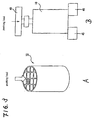
- the honeycomb structure 10 was mounted on a base 45, and a punching load (1 mm/min in pressing speed) was applied to a porous ceramic member in the center of the honeycomb structure 10 by an aluminum jig 40 having a diameter of 30 mm.
- a punching load (1 mm/min in pressing speed) was applied to a porous ceramic member in the center of the honeycomb structure 10 by an aluminum jig 40 having a diameter of 30 mm.
- An Instron universal tester 5582 type was used for measuring the strength.
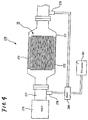
- Fig. 4 is an explanatory view of the collecting efficiency measuring system.
- the collecting efficiency measuring system 270 was arranged as a scanning mobility particle sizer (SMPS) having a 2L common-rail type diesel engine 276, an exhaust gas pipe 277 allowing exhaust gas to flow from the engine 276, a metal casing 271 connected to the exhaust gas pipe 277 and fixing the honeycomb structure 10 wrapped in an alumina mat 272, a sampler 278 sampling the exhaust gas which had not yet flowed into the honeycomb structure 10, a sampler 279 sampling the exhaust gas which had flowed through the honeycomb structure 10, a diluter 280 diluting the exhaust gas sampled by each sampler 278, 279, and a PM counter 281 (condensation particle counter 3022AS made by TSI Incorporated) measuring the amount of particulates included in the diluted exhaust gas.
- SMPS scanning mobility particle sizer
- the honeycomb structure 10 heated to 800°C and then rapidly cooled down to the room temperature was used, similarly to the sample used for measuring the pushing (punching) strength in the aforementioned measurement (2).
- the pushing (punching) strength was not higher than 1/3 of that of any honeycomb structure of Examples. Further, the collecting efficiency was not higher than 80% of that of any honeycomb structure of Examples. It can be considered that this is because there occurred a failure such as a crack in the honeycomb structure and/or the adhesive layer at the time of heat treatment.
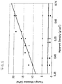
- Fig. 5 shows a graph in which the examples 1 to 16 (including References Examples 1 to 6 and 8 to 16 and inventive Example 7) and the comparative examples 1 to 11 are plotted on the basis of the tables 1 to 3.
- the abscissa axis represents apparent density (g/cm 3 ) of the porous cell member, and the ordinate axis represents Young's modulus (GPa) of the adhesive layer.
Landscapes
- Chemical & Material Sciences (AREA)
- Chemical Kinetics & Catalysis (AREA)
- Engineering & Computer Science (AREA)
- Geometry (AREA)
- Physics & Mathematics (AREA)
- Combustion & Propulsion (AREA)
- Mechanical Engineering (AREA)
- General Engineering & Computer Science (AREA)
- Environmental & Geological Engineering (AREA)
- Ceramic Engineering (AREA)
- Materials Engineering (AREA)
- Organic Chemistry (AREA)
- Health & Medical Sciences (AREA)
- Geology (AREA)
- General Chemical & Material Sciences (AREA)
- Analytical Chemistry (AREA)
- Biomedical Technology (AREA)
- Inorganic Chemistry (AREA)
- Life Sciences & Earth Sciences (AREA)
- Oil, Petroleum & Natural Gas (AREA)
- Filtering Materials (AREA)
- Catalysts (AREA)
- Solid-Sorbent Or Filter-Aiding Compositions (AREA)
- Laminated Bodies (AREA)
- Materials For Medical Uses (AREA)
- Filtering Of Dispersed Particles In Gases (AREA)
- Exhaust Gas Treatment By Means Of Catalyst (AREA)
- Processes For Solid Components From Exhaust (AREA)
Claims (2)
- Wabenstruktur, wobei:mehrere poröse, keramische Elemente (20) durch eine Haftvermittlerschicht (11) verbunden sind, jedes der porösen, keramischen Elemente (20) mehrere Zellen (21) aufweist, welche, durch Zellwände (23) getrennt, parallel zueinander angeordnet sind und die Zellen sich in einer Längsrichtung der Wabenstruktur (10) erstrecken, wobeidie porösen keramischen Elemente (20) wie folgt gebildet sind:7000 Gewichtsteile eines groben α-Siliziumcarbidpulvers, das eine durchschnittliche Partikelgröße von 22 µm aufweist und 3000 Gewichtsteile eines feinen α-Siliziumcarbidpulvers, das eine durchschnittliche Partikelgröße von 0,5 µm hat werden nass vermischt;weiter werden 1100 Gewichtsteile eines organischen Bindemittels, d.h. Methylzellulose, 330 Gewichtsteile eines Weichmachers, 150 Gewichtsteile eines Schmiermittels, d.h. Glyzerin und eine passende Menge an Wasser zugefügt und geknetet, um eine Gemischzusammensetzung zu erhalten;danach wird die Gemischzusammensetzung extrudiert, um einen prismatischen rohen Formkörper herzustellen;als nächstes wird der rohe Formkörper unter Verwendung eines Mikrowellentrockners oder dergleichen getrocknet, um einen keramischen getrockneten Körper auszubilden;danach werden vorbestimmte Zellen mit einer Pfropfenpaste, deren Zusammensetzung ähnlich der Zusammensetzung des rohen Formkörpers ist, verstopft;als nächstes wird der rohe Formkörper erneut durch den Trockner getrocknet, dann bei 400 °C entgast und bei 2200 °C für drei Stunden unter Argonatmosphäre unter Normaldruck gefeuert; damit ein poröses keramisches Element hergestellt wird, das aus einem Siliziumcarbid-Sinter gebildet ist, eine Porosität von 45% hat, eine durchschnittliche Porengröße von 11 µm aufweist und das poröse keramische Element 34,3 mm auf 34,3 mm auf 150 mm misst, und eine Anzahl an Zellen von 21 hat, d.h. eine Zelldichte von 46,5 Zellen/cm2, die Dicke der Zellwände 0,25 mm beträgt, die Rohdichte 0,55 (g/cm3) beträgt und das Öffnungsflächenverhältnis 68,8% beträgt,wobei die Haftvermittlerschicht (11) und die Wabenstruktur wie folgt gebildet werden:30 Gewichtsteile Siliziumcarbidpulver, das eine durchschnittliche Partikelgröße von 0,5 µm hat, 7 Gewichtsteile Kieselsol mit einem SiO2 Gehalt von 30 Gew.-%, 63 Gewichtsteile Silica-Aluminiumoxid Fasern mit einem durchschnittlichen Faserdurchmesser von 3 µm und einer durchschnittlichen Faserlänge von 60 µm, 0,5 Gewichtsteile Carboxymethylcellulose und Wasser werden gemischt und geknetet;wobei in der Herstellung der Haftvermittlerpaste eine notwendige Menge an Wasser zugefügt wird, so dass die Viskosität der Haftvermittlerpaste 40 ± 5P war;wobei das Youngmodul der Haftvermittlerpaste 5 GPa ist;Verwenden der Haftvermittlerpaste als 2 mm dicke Haftvermittlerschicht, 16, d.h. 4 auf 4 poröse keramische Elemente werden gebunden und nacheinander durch einen Diamantschneider geschnitten, so dass ein zylindrischer keramischer Block hergestellt wird;als nächstes wird die Haftvermittlerpaste als Mantelformpaste verwendet und auf den äußeren Umfangsabschnitt des keramischen Blocks (15) aufgetragen, so dass sie 0,5 mm dick ist und dann bei 120 °C getrocknet; so dass eine zylindrische Wabenstruktur hergestellt wird, die 143,8 mm im Durchmesser und 150 mm in der Länge misst.
- Wabenstruktur nach einem der Anspruche 1, wobei in mindestens einem Teilbereich von den Zellwänden (23) ein Katalysator getragen und gelagert ist.
Priority Applications (1)
| Application Number | Priority Date | Filing Date | Title |
|---|---|---|---|
| PL06007509T PL1710015T3 (pl) | 2005-04-08 | 2006-04-10 | Struktura typu plastra miodu |
Applications Claiming Priority (1)
| Application Number | Priority Date | Filing Date | Title |
|---|---|---|---|
| JP2005112254A JP2006289237A (ja) | 2005-04-08 | 2005-04-08 | ハニカム構造体 |
Publications (3)
| Publication Number | Publication Date |
|---|---|
| EP1710015A1 EP1710015A1 (de) | 2006-10-11 |
| EP1710015B1 EP1710015B1 (de) | 2009-06-17 |
| EP1710015B2 true EP1710015B2 (de) | 2016-09-07 |
Family
ID=36603611
Family Applications (1)
| Application Number | Title | Priority Date | Filing Date |
|---|---|---|---|
| EP06007509.0A Expired - Lifetime EP1710015B2 (de) | 2005-04-08 | 2006-04-10 | Keramischer Wabenkörper |
Country Status (8)
| Country | Link |
|---|---|
| US (1) | US7556666B2 (de) |
| EP (1) | EP1710015B2 (de) |
| JP (1) | JP2006289237A (de) |
| KR (1) | KR100751629B1 (de) |
| CN (1) | CN100408817C (de) |
| AT (1) | ATE433799T1 (de) |
| DE (1) | DE602006007260D1 (de) |
| PL (1) | PL1710015T3 (de) |
Families Citing this family (116)
| Publication number | Priority date | Publication date | Assignee | Title |
|---|---|---|---|---|
| DE60033977T2 (de) | 1999-09-29 | 2007-12-20 | Ibiden Co., Ltd., Ogaki | Wabenförmiger Filter und Anordnung von keramischen Filtern |
| JPWO2003067041A1 (ja) | 2002-02-05 | 2005-06-02 | イビデン株式会社 | 排気ガス浄化用ハニカムフィルタ、接着剤、塗布材、及び、排気ガス浄化用ハニカムフィルタの製造方法 |
| EP1479882B2 (de) * | 2002-02-05 | 2012-08-22 | Ibiden Co., Ltd. | Wabenfilter für abgasentgiftung |
| US7427308B2 (en) * | 2002-03-04 | 2008-09-23 | Ibiden Co., Ltd. | Honeycomb filter for exhaust gas decontamination and exhaust gas decontamination apparatus |
| ATE376880T1 (de) * | 2002-03-22 | 2007-11-15 | Ibiden Co Ltd | Herstellungsverfahren eines wabenfilters zur reinigung von abgas |
| CN100371562C (zh) * | 2002-04-10 | 2008-02-27 | 揖斐电株式会社 | 废气净化用蜂窝状过滤器 |
| EP1500799B1 (de) * | 2002-04-11 | 2007-10-24 | Ibiden Co., Ltd. | Wabenfilter zur reinigung von abgas |
| ATE481151T1 (de) | 2003-02-28 | 2010-10-15 | Ibiden Co Ltd | Keramische wabenstruktur |
| WO2005026074A1 (ja) * | 2003-09-12 | 2005-03-24 | Ibiden Co., Ltd. | セラミック焼結体およびセラミックフィルタ |
| JP4849891B2 (ja) * | 2003-11-05 | 2012-01-11 | イビデン株式会社 | ハニカム構造体の製造方法 |
| EP1790623B1 (de) * | 2003-11-12 | 2009-05-13 | Ibiden Co., Ltd. | Verfahren zur Herstellung der Keramikstruktur |
| US7387829B2 (en) * | 2004-01-13 | 2008-06-17 | Ibiden Co., Ltd. | Honeycomb structure, porous body, pore forming material for the porous body, and methods for manufacturing the pore forming material, the porous body and the honeycomb structure |
| WO2005099865A1 (ja) * | 2004-04-05 | 2005-10-27 | Ibiden Co., Ltd. | ハニカム構造体、ハニカム構造体の製造方法及び排気ガス浄化装置 |
| JPWO2005108328A1 (ja) | 2004-05-06 | 2008-03-21 | イビデン株式会社 | ハニカム構造体及びその製造方法 |
| EP1930058A3 (de) * | 2004-05-18 | 2008-07-30 | Ibiden Co., Ltd. | Wabenstrukturkörper und Abgasreinigungsvorrichtung |
| WO2006003736A1 (ja) * | 2004-07-01 | 2006-01-12 | Ibiden Co., Ltd. | セラミック焼成用治具及び多孔質セラミック体の製造方法 |
| JPWO2006013651A1 (ja) * | 2004-08-04 | 2008-05-01 | イビデン株式会社 | 焼成炉及びこれを用いた多孔質セラミック部材の製造方法 |
| WO2006035822A1 (ja) | 2004-09-30 | 2006-04-06 | Ibiden Co., Ltd. | ハニカム構造体 |
| EP1795261A4 (de) * | 2004-09-30 | 2009-07-08 | Ibiden Co Ltd | Wabenstruktur |
| DE602005015610D1 (de) * | 2004-10-12 | 2009-09-03 | Ibiden Co Ltd | Keramische wabenstruktur |
| EP1818098A4 (de) * | 2004-11-26 | 2008-02-06 | Ibiden Co Ltd | Wabenstruktur |
| CN101010266A (zh) * | 2005-02-04 | 2007-08-01 | 揖斐电株式会社 | 陶瓷蜂窝结构体 |
| WO2006082938A1 (ja) * | 2005-02-04 | 2006-08-10 | Ibiden Co., Ltd. | セラミックハニカム構造体およびその製造方法 |
| JP2006223983A (ja) * | 2005-02-17 | 2006-08-31 | Ibiden Co Ltd | ハニカム構造体 |
| JP4812316B2 (ja) * | 2005-03-16 | 2011-11-09 | イビデン株式会社 | ハニカム構造体 |
| KR100810476B1 (ko) * | 2005-03-28 | 2008-03-07 | 이비덴 가부시키가이샤 | 허니컴 구조체 |
| JP4870559B2 (ja) * | 2005-03-28 | 2012-02-08 | イビデン株式会社 | ハニカム構造体 |
| JPWO2006112052A1 (ja) * | 2005-03-30 | 2008-11-27 | イビデン株式会社 | 炭化珪素含有粒子、炭化珪素質焼結体を製造する方法、炭化珪素質焼結体、及びフィルター |
| KR100822246B1 (ko) | 2005-04-07 | 2008-04-16 | 이비덴 가부시키가이샤 | 허니컴 구조체 |
| JP4937116B2 (ja) * | 2005-04-28 | 2012-05-23 | イビデン株式会社 | ハニカム構造体 |
| JP4854664B2 (ja) * | 2005-06-06 | 2012-01-18 | イビデン株式会社 | ハニカム構造体の輸送方法 |
| CN1954137B (zh) * | 2005-07-21 | 2011-12-21 | 揖斐电株式会社 | 蜂窝结构体以及废气净化装置 |
| WO2007015550A1 (ja) * | 2005-08-03 | 2007-02-08 | Ibiden Co., Ltd. | 炭化珪素質焼成用治具及び多孔質炭化珪素体の製造方法 |
| CN100540111C (zh) * | 2005-08-26 | 2009-09-16 | 揖斐电株式会社 | 蜂窝结构体及其制造方法 |
| WO2007037222A1 (ja) * | 2005-09-28 | 2007-04-05 | Ibiden Co., Ltd. | ハニカムフィルタ |
| JP2007098274A (ja) * | 2005-10-04 | 2007-04-19 | Ibiden Co Ltd | 多孔質ハニカム構造体及びそれを利用した排ガス浄化装置 |
| JPWO2007039991A1 (ja) * | 2005-10-05 | 2009-04-16 | イビデン株式会社 | 押出成形用金型及び多孔質セラミック部材の製造方法 |
| KR100831836B1 (ko) * | 2005-10-12 | 2008-05-28 | 이비덴 가부시키가이샤 | 벌집형 유닛 및 벌집형 구조체 |
| KR100882401B1 (ko) * | 2005-11-18 | 2009-02-05 | 이비덴 가부시키가이샤 | 벌집형 구조체 |
| CN101312809A (zh) * | 2005-12-26 | 2008-11-26 | 揖斐电株式会社 | 蜂窝结构体的制造方法 |
| WO2007074528A1 (ja) * | 2005-12-27 | 2007-07-05 | Ibiden Co., Ltd. | 脱脂用治具、セラミック成形体の脱脂方法、及び、ハニカム構造体の製造方法 |
| CN101309883B (zh) * | 2006-01-27 | 2012-12-26 | 揖斐电株式会社 | 蜂窝结构体及其制造方法 |
| WO2007086143A1 (ja) * | 2006-01-30 | 2007-08-02 | Ibiden Co., Ltd. | ハニカム構造体の検査方法、及び、ハニカム構造体の製造方法 |
| WO2007094075A1 (ja) * | 2006-02-17 | 2007-08-23 | Ibiden Co., Ltd. | 乾燥用治具組立装置、乾燥用治具分解装置、乾燥用治具循環装置、セラミック成形体の乾燥方法、及び、ハニカム構造体の製造方法 |
| WO2007096986A1 (ja) | 2006-02-24 | 2007-08-30 | Ibiden Co., Ltd. | 端面加熱装置、ハニカム集合体の端面乾燥方法、及び、ハニカム構造体の製造方法 |
| WO2007097004A1 (ja) * | 2006-02-24 | 2007-08-30 | Ibiden Co., Ltd. | 湿式混合機、湿式混合方法及びハニカム構造体の製造方法 |
| WO2007097000A1 (ja) * | 2006-02-24 | 2007-08-30 | Ibiden Co., Ltd. | ハニカム成形体用封口装置、封止材ペーストの充填方法、及び、ハニカム構造体の製造方法 |
| DE602006002244D1 (de) * | 2006-02-28 | 2008-09-25 | Ibiden Co Ltd | Trageelement für Trocknung, Trocknungsverfahren eines Presslings mit Wabenstruktur, und Verfahren zur Herstellung eines Wabenkörpers. |
| WO2007102216A1 (ja) * | 2006-03-08 | 2007-09-13 | Ibiden Co., Ltd. | 脱脂炉投入装置、及び、ハニカム構造体の製造方法 |
| WO2007102217A1 (ja) * | 2006-03-08 | 2007-09-13 | Ibiden Co., Ltd. | 焼成体用冷却機、焼成炉、セラミック焼成体の冷却方法、及び、ハニカム構造体の製造方法 |
| WO2007108076A1 (ja) * | 2006-03-17 | 2007-09-27 | Ibiden Co., Ltd. | 乾燥装置、セラミック成形体の乾燥方法及びハニカム構造体の製造方法 |
| KR101081638B1 (ko) | 2006-03-30 | 2011-11-09 | 엔지케이 인슐레이터 엘티디 | 접합체, 허니컴 세그먼트 접합체, 및 그것을 이용한 허니컴 구조체 |
| JP4863904B2 (ja) | 2006-03-31 | 2012-01-25 | イビデン株式会社 | ハニカム構造体およびその製造方法 |
| WO2007116529A1 (ja) * | 2006-04-11 | 2007-10-18 | Ibiden Co., Ltd. | 成形体切断装置、セラミック成形体の切断方法、及び、ハニカム構造体の製造方法 |
| WO2007122680A1 (ja) * | 2006-04-13 | 2007-11-01 | Ibiden Co., Ltd. | 押出成形機、押出成形方法及びハニカム構造体の製造方法 |
| WO2007122707A1 (ja) * | 2006-04-19 | 2007-11-01 | Ibiden Co., Ltd. | ハニカム構造体の製造方法 |
| WO2007122715A1 (ja) * | 2006-04-20 | 2007-11-01 | Ibiden Co., Ltd. | ハニカム焼成体の検査方法、及び、ハニカム構造体の製造方法 |
| WO2007122716A1 (ja) * | 2006-04-20 | 2007-11-01 | Ibiden Co., Ltd. | 搬送装置、及び、ハニカム構造体の製造方法 |
| WO2007129391A1 (ja) * | 2006-05-01 | 2007-11-15 | Ibiden Co., Ltd. | 焼成用治具組立装置、焼成用治具分解装置、循環装置、セラミック成形体の焼成方法、及び、ハニカム構造体の製造方法 |
| WO2007129399A1 (ja) * | 2006-05-08 | 2007-11-15 | Ibiden Co., Ltd. | ハニカム構造体の製造方法、ハニカム成形体受取機及びハニカム成形体取出機 |
| WO2007132530A1 (ja) * | 2006-05-17 | 2007-11-22 | Ibiden Co., Ltd. | ハニカム成形体用端面処理装置、ハニカム成形体の封止方法、及び、ハニカム構造体の製造方法 |
| WO2007138701A1 (ja) * | 2006-05-31 | 2007-12-06 | Ibiden Co., Ltd. | 把持装置、及び、ハニカム構造体の製造方法 |
| FR2902424B1 (fr) * | 2006-06-19 | 2008-10-17 | Saint Gobain Ct Recherches | Ciment de jointoiement a spheres creuses pour filtre a particules. |
| PL1875997T3 (pl) * | 2006-07-07 | 2009-08-31 | Ibiden Co Ltd | Urządzenie do obróbki powierzchni czołowej, sposób obróbki powierzchni czołowej formowanego korpusu o strukturze plastra miodu oraz sposób wytwarzania struktury o kształcie plastra miodu |
| NO327431B1 (no) * | 2006-09-08 | 2009-06-29 | Yara Int Asa | Fremgangsmate og anordning for fangst av platinagruppeelementer |
| WO2008032390A1 (fr) * | 2006-09-14 | 2008-03-20 | Ibiden Co., Ltd. | Procédé de production d'une structure en nid d'abeille |
| DE602006014830D1 (de) * | 2006-09-14 | 2010-07-22 | Ibiden Co Ltd | Verfahren zur Herstellung eines Wabenkörpers und Zusammensetzung für Sinterwabenkörper |
| WO2008032391A1 (fr) * | 2006-09-14 | 2008-03-20 | Ibiden Co., Ltd. | Procédé de production d'une structure en nid d'abeille et composition de matière première pour nid d'abeille calciné |
| WO2008047404A1 (fr) * | 2006-10-16 | 2008-04-24 | Ibiden Co., Ltd. | Support de montage pour structure alvéolaire et dispositif d'inspection pour structure alvéolaire |
| EP1930061B1 (de) * | 2006-12-07 | 2018-10-03 | NGK Insulators, Ltd. | Bindungsmaterialzusammensetzung und herstellungsverfahren dafür, verbundener körper und herstellungsverfahren dafür |
| EP1939261B1 (de) * | 2006-12-25 | 2010-03-31 | Ngk Insulators, Ltd. | Verbundener Körper und Herstellungsverfahren dafür |
| US8894916B2 (en) | 2006-12-27 | 2014-11-25 | Hitachi Metals, Ltd. | Method for producing aluminum-titanate-based ceramic honeycomb structure |
| EP1941940A1 (de) * | 2007-01-03 | 2008-07-09 | Ford Global Technologies, LLC | Poröses Substrat zur Verwendung als Partikelfilter für katalytisch oder nicht katalytisch Rußregenerationsverfahren |
| WO2008090625A1 (ja) * | 2007-01-26 | 2008-07-31 | Ibiden Co., Ltd. | 外周層形成装置及びハニカム構造体の製造方法 |
| US20080178992A1 (en) * | 2007-01-31 | 2008-07-31 | Geo2 Technologies, Inc. | Porous Substrate and Method of Fabricating the Same |
| JP5241235B2 (ja) * | 2007-02-28 | 2013-07-17 | イビデン株式会社 | ハニカム構造体の製造方法 |
| WO2008105082A1 (ja) * | 2007-02-28 | 2008-09-04 | Ibiden Co., Ltd. | ハニカム構造体 |
| WO2008105081A1 (ja) * | 2007-02-28 | 2008-09-04 | Ibiden Co., Ltd. | ハニカムフィルタ |
| WO2008126320A1 (ja) * | 2007-03-30 | 2008-10-23 | Ibiden Co., Ltd. | ハニカム構造体の製造方法 |
| WO2008126334A1 (ja) * | 2007-03-30 | 2008-10-23 | Ibiden Co., Ltd. | ハニカム構造体の製造方法 |
| WO2008126330A1 (ja) * | 2007-03-30 | 2008-10-23 | Ibiden Co., Ltd. | ハニカム構造体 |
| WO2008126335A1 (ja) * | 2007-03-30 | 2008-10-23 | Ibiden Co., Ltd. | ハニカム構造体及びハニカム構造体の製造方法 |
| WO2008126332A1 (ja) | 2007-03-30 | 2008-10-23 | Ibiden Co., Ltd. | ハニカムフィルタ |
| JP5063604B2 (ja) * | 2007-03-30 | 2012-10-31 | イビデン株式会社 | ハニカムフィルタ |
| WO2008126333A1 (ja) * | 2007-03-30 | 2008-10-23 | Ibiden Co., Ltd. | ハニカム構造体 |
| JPWO2008126321A1 (ja) * | 2007-03-30 | 2010-07-22 | イビデン株式会社 | 排ガス浄化システム |
| WO2008136078A1 (ja) * | 2007-04-20 | 2008-11-13 | Ibiden Co., Ltd. | ハニカムフィルタ |
| WO2008139581A1 (ja) * | 2007-05-09 | 2008-11-20 | Ibiden Co., Ltd. | 炭化ケイ素焼成用原料の製造方法、及び、ハニカム構造体の製造方法 |
| WO2008139608A1 (ja) * | 2007-05-14 | 2008-11-20 | Ibiden Co., Ltd. | ハニカム構造体及び該ハニカム構造体の製造方法 |
| WO2008149435A1 (ja) * | 2007-06-06 | 2008-12-11 | Ibiden Co., Ltd. | 焼成用治具及びハニカム構造体の製造方法 |
| PL2173981T3 (pl) * | 2007-06-13 | 2019-06-28 | 3M Innovative Properties Company | Odporny materiał montażowy oraz sposób jego wytwarzania i stosowania |
| EP2487342B1 (de) * | 2007-06-13 | 2018-04-18 | 3M Innovative Properties Company | Erosionsbeständiges Montagematerial und Verfahren zu seiner Herstellung und Verwendung |
| WO2008155856A1 (ja) * | 2007-06-21 | 2008-12-24 | Ibiden Co., Ltd. | ハニカム構造体、及び、ハニカム構造体の製造方法 |
| JP5180835B2 (ja) * | 2007-10-31 | 2013-04-10 | イビデン株式会社 | ハニカム構造体用梱包体、及び、ハニカム構造体の輸送方法 |
| WO2009066388A1 (ja) * | 2007-11-21 | 2009-05-28 | Ibiden Co., Ltd. | ハニカム構造体及びハニカム構造体の製造方法 |
| US8114354B2 (en) | 2007-12-18 | 2012-02-14 | Basf Corporation | Catalyzed soot filter manufacture and systems |
| WO2009101683A1 (ja) | 2008-02-13 | 2009-08-20 | Ibiden Co., Ltd. | ハニカム構造体の製造方法 |
| WO2009101682A1 (ja) * | 2008-02-13 | 2009-08-20 | Ibiden Co., Ltd. | ハニカム構造体、排ガス浄化装置、及び、ハニカム構造体の製造方法 |
| JP5234973B2 (ja) * | 2008-02-14 | 2013-07-10 | イビデン株式会社 | ハニカム構造体 |
| WO2009101691A1 (ja) * | 2008-02-14 | 2009-08-20 | Ibiden Co., Ltd. | ハニカム構造体 |
| WO2009107230A1 (ja) * | 2008-02-29 | 2009-09-03 | イビデン株式会社 | ハニカム構造体用シール材、ハニカム構造体、及び、ハニカム構造体の製造方法 |
| WO2009118813A1 (ja) * | 2008-03-24 | 2009-10-01 | イビデン株式会社 | ハニカム構造体及びハニカム構造体の製造方法 |
| WO2009118814A1 (ja) * | 2008-03-24 | 2009-10-01 | イビデン株式会社 | ハニカムフィルタ |
| WO2009118862A1 (ja) * | 2008-03-27 | 2009-10-01 | イビデン株式会社 | ハニカム構造体の製造方法 |
| KR101784013B1 (ko) | 2008-12-15 | 2017-10-10 | 유니프랙스 아이 엘엘씨 | 세라믹 허니콤 구조체의 스킨 코팅 |
| EP2656900B1 (de) * | 2010-12-24 | 2018-03-28 | NGK Insulators, Ltd. | Wabenstruktur |
| JP5643692B2 (ja) * | 2011-03-25 | 2014-12-17 | 日本碍子株式会社 | ハニカムフィルタ及びその製造方法 |
| WO2013024547A1 (ja) * | 2011-08-18 | 2013-02-21 | イビデン株式会社 | ハニカム構造体及びその製造方法、排ガス浄化装置並びにシリコアルミノホスフェート粒子 |
| JP5814373B2 (ja) * | 2011-08-18 | 2015-11-17 | イビデン株式会社 | ハニカム構造体及びその製造方法、排ガス浄化装置並びにシリコアルミノホスフェート粒子 |
| JP5990572B2 (ja) * | 2012-03-29 | 2016-09-14 | イビデン株式会社 | ハニカム構造体、排ガス浄化用ハニカムフィルタ及び排ガス浄化装置 |
| JP6581934B2 (ja) | 2016-03-24 | 2019-09-25 | 日本碍子株式会社 | ハニカムフィルタ |
| US20210395154A1 (en) * | 2018-11-15 | 2021-12-23 | Corning Incorporated | Conductive ceramic honeycombs with resistive heating capability and methods of making the same |
| WO2022026820A1 (en) * | 2020-07-31 | 2022-02-03 | Corning Incorporated | Catalyst loaded honeycomb bodies made from beads with open porosity |
| WO2022026664A1 (en) | 2020-07-31 | 2022-02-03 | Corning Incorporated | Ceramic articles made from ceramic beads with open porosity |
| JP7594398B2 (ja) * | 2020-09-24 | 2024-12-04 | イビデン株式会社 | 電気加熱式触媒 |
| CN115368159B (zh) * | 2022-08-17 | 2023-09-01 | 浙江理工大学 | 一种三角形蜂窝多孔陶瓷材料的制备方法 |
Citations (3)
| Publication number | Priority date | Publication date | Assignee | Title |
|---|---|---|---|---|
| EP1437168A1 (de) † | 2001-10-15 | 2004-07-14 | Ngk Insulators, Ltd. | Wabenfilter |
| EP1479881A1 (de) † | 2002-02-05 | 2004-11-24 | Ibiden Co., Ltd. | Wabenfilter für abgasreinigung, klebstoff, beschichtungsmaterial und verfahren zur herstellung eines wabenfilters zur abgasreinigung |
| EP1479882A1 (de) † | 2002-02-05 | 2004-11-24 | Ibiden Co., Ltd. | Wabenfilter für abgasentgiftung |
Family Cites Families (34)
| Publication number | Priority date | Publication date | Assignee | Title |
|---|---|---|---|---|
| GB2064360B (en) * | 1979-12-03 | 1984-05-16 | Gen Motors Corp | Ceramic filters for diesel exhaust particulates and methods for making such filters |
| JPS6396717A (ja) * | 1986-10-09 | 1988-04-27 | Matsushita Electric Ind Co Ltd | 回転ヘツド装置 |
| JP2505261B2 (ja) * | 1988-09-29 | 1996-06-05 | 日本碍子株式会社 | セラミック熱交換体およびその製造法 |
| US5914187A (en) * | 1996-01-12 | 1999-06-22 | Ibiden Co., Ltd. | Ceramic structural body |
| DE60033977T2 (de) * | 1999-09-29 | 2007-12-20 | Ibiden Co., Ltd., Ogaki | Wabenförmiger Filter und Anordnung von keramischen Filtern |
| JP3889194B2 (ja) * | 2000-01-13 | 2007-03-07 | 日本碍子株式会社 | ハニカム構造体 |
| JP2001190917A (ja) * | 2000-01-13 | 2001-07-17 | Ngk Insulators Ltd | 三角セルハニカム構造体 |
| JP3997825B2 (ja) * | 2001-06-28 | 2007-10-24 | 株式会社デンソー | セラミックフィルタおよび触媒付セラミックフィルタ |
| JP5189236B2 (ja) | 2001-07-25 | 2013-04-24 | 日本碍子株式会社 | 排ガス浄化用ハニカム構造体及び排ガス浄化用ハニカム触媒体 |
| JP4367683B2 (ja) * | 2001-10-09 | 2009-11-18 | 日本碍子株式会社 | ハニカムフィルター |
| JP4293753B2 (ja) * | 2002-03-19 | 2009-07-08 | 日本碍子株式会社 | ハニカムフィルター |
| JP2004000896A (ja) * | 2002-03-25 | 2004-01-08 | Ngk Insulators Ltd | ハニカムフィルター |
| US7090714B2 (en) * | 2002-06-17 | 2006-08-15 | Hitachi Metals, Ltd. | Ceramic honeycomb filter |
| JP2004188278A (ja) * | 2002-12-09 | 2004-07-08 | Ibiden Co Ltd | 排気ガス浄化用ハニカムフィルタ |
| KR100932835B1 (ko) * | 2003-03-21 | 2009-12-21 | 주식회사한국야쿠르트 | 카뎁신 케이의 활성을 저해하는 번데기동충하초 추출물 |
| WO2005026074A1 (ja) | 2003-09-12 | 2005-03-24 | Ibiden Co., Ltd. | セラミック焼結体およびセラミックフィルタ |
| EP1785603B1 (de) * | 2004-08-31 | 2009-06-24 | Ibiden Co., Ltd. | Abgasreinigungssystem |
| JP2006223983A (ja) | 2005-02-17 | 2006-08-31 | Ibiden Co Ltd | ハニカム構造体 |
| JP4937116B2 (ja) | 2005-04-28 | 2012-05-23 | イビデン株式会社 | ハニカム構造体 |
| CN1954137B (zh) | 2005-07-21 | 2011-12-21 | 揖斐电株式会社 | 蜂窝结构体以及废气净化装置 |
| CN100540111C (zh) | 2005-08-26 | 2009-09-16 | 揖斐电株式会社 | 蜂窝结构体及其制造方法 |
| WO2007037222A1 (ja) | 2005-09-28 | 2007-04-05 | Ibiden Co., Ltd. | ハニカムフィルタ |
| KR100831836B1 (ko) | 2005-10-12 | 2008-05-28 | 이비덴 가부시키가이샤 | 벌집형 유닛 및 벌집형 구조체 |
| US7938877B2 (en) * | 2005-11-16 | 2011-05-10 | Geo2 Technologies, Inc. | Low coefficient of thermal expansion materials including modified aluminosilicate fibers and methods of manufacture |
| JPWO2007058006A1 (ja) | 2005-11-18 | 2009-04-30 | イビデン株式会社 | ハニカム構造体 |
| KR100882401B1 (ko) | 2005-11-18 | 2009-02-05 | 이비덴 가부시키가이샤 | 벌집형 구조체 |
| EP1806329A3 (de) * | 2006-01-05 | 2008-09-03 | Asahi Glass Company, Limited | Zusammensetzung für keramische Bindung und keramisch gebundenes Element |
| CN101309883B (zh) | 2006-01-27 | 2012-12-26 | 揖斐电株式会社 | 蜂窝结构体及其制造方法 |
| JPWO2007097056A1 (ja) | 2006-02-23 | 2009-07-09 | イビデン株式会社 | ハニカム構造体および排ガス浄化装置 |
| JP4863904B2 (ja) | 2006-03-31 | 2012-01-25 | イビデン株式会社 | ハニカム構造体およびその製造方法 |
| WO2008099450A1 (ja) | 2007-02-09 | 2008-08-21 | Ibiden Co., Ltd. | ハニカム構造体および排気ガス処理装置 |
| WO2008099454A1 (ja) | 2007-02-09 | 2008-08-21 | Ibiden Co., Ltd. | ハニカム構造体および排気ガス処理装置 |
| WO2008120386A1 (ja) | 2007-03-29 | 2008-10-09 | Ibiden Co., Ltd. | ハニカム構造体 |
| JP5164575B2 (ja) | 2007-03-29 | 2013-03-21 | イビデン株式会社 | ハニカム構造体、ハニカム構造体の製造方法、排ガス浄化装置及び排ガス浄化装置の製造方法 |
-
2005
- 2005-04-08 JP JP2005112254A patent/JP2006289237A/ja active Pending
-
2006
- 2006-04-05 US US11/278,782 patent/US7556666B2/en active Active
- 2006-04-06 KR KR1020060031469A patent/KR100751629B1/ko not_active Expired - Lifetime
- 2006-04-07 CN CNB2006100726786A patent/CN100408817C/zh not_active Expired - Lifetime
- 2006-04-10 PL PL06007509T patent/PL1710015T3/pl unknown
- 2006-04-10 AT AT06007509T patent/ATE433799T1/de not_active IP Right Cessation
- 2006-04-10 DE DE602006007260T patent/DE602006007260D1/de not_active Expired - Lifetime
- 2006-04-10 EP EP06007509.0A patent/EP1710015B2/de not_active Expired - Lifetime
Patent Citations (3)
| Publication number | Priority date | Publication date | Assignee | Title |
|---|---|---|---|---|
| EP1437168A1 (de) † | 2001-10-15 | 2004-07-14 | Ngk Insulators, Ltd. | Wabenfilter |
| EP1479881A1 (de) † | 2002-02-05 | 2004-11-24 | Ibiden Co., Ltd. | Wabenfilter für abgasreinigung, klebstoff, beschichtungsmaterial und verfahren zur herstellung eines wabenfilters zur abgasreinigung |
| EP1479882A1 (de) † | 2002-02-05 | 2004-11-24 | Ibiden Co., Ltd. | Wabenfilter für abgasentgiftung |
Also Published As
| Publication number | Publication date |
|---|---|
| US20060230732A1 (en) | 2006-10-19 |
| EP1710015A1 (de) | 2006-10-11 |
| PL1710015T3 (pl) | 2010-01-29 |
| CN1844645A (zh) | 2006-10-11 |
| KR100751629B1 (ko) | 2007-08-22 |
| EP1710015B1 (de) | 2009-06-17 |
| ATE433799T1 (de) | 2009-07-15 |
| JP2006289237A (ja) | 2006-10-26 |
| DE602006007260D1 (de) | 2009-07-30 |
| US7556666B2 (en) | 2009-07-07 |
| KR20060107379A (ko) | 2006-10-13 |
| CN100408817C (zh) | 2008-08-06 |
Similar Documents
| Publication | Publication Date | Title |
|---|---|---|
| EP1710015B2 (de) | Keramischer Wabenkörper | |
| EP1703096B1 (de) | Wabenstruktur | |
| EP1795262B1 (de) | Wabenstruktur | |
| US7540898B2 (en) | Honeycomb structured body | |
| EP1977809B1 (de) | Wabenfilter | |
| EP1514588B1 (de) | Wabenstrukturkörper | |
| US7449427B2 (en) | Honeycomb structured body | |
| US7981370B2 (en) | Honeycomb filter and exhaust gas purifying apparatus | |
| JP4932256B2 (ja) | セラミック焼結体およびセラミックフィルタ | |
| KR100855167B1 (ko) | 벌집형 구조체 | |
| EP1965047B1 (de) | Wabenstrukturkörper | |
| JPWO2006106785A1 (ja) | ハニカム構造体 | |
| EP2090559A1 (de) | Wabenstrukturkörper | |
| EP1787702B1 (de) | Wabenstrukturkörper |
Legal Events
| Date | Code | Title | Description |
|---|---|---|---|
| PUAI | Public reference made under article 153(3) epc to a published international application that has entered the european phase |
Free format text: ORIGINAL CODE: 0009012 |
|
| AK | Designated contracting states |
Kind code of ref document: A1 Designated state(s): AT BE BG CH CY CZ DE DK EE ES FI FR GB GR HU IE IS IT LI LT LU LV MC NL PL PT RO SE SI SK TR |
|
| AX | Request for extension of the european patent |
Extension state: AL BA HR MK YU |
|
| 17P | Request for examination filed |
Effective date: 20061103 |
|
| 17Q | First examination report despatched |
Effective date: 20061212 |
|
| AKX | Designation fees paid |
Designated state(s): AT BE BG CH CY CZ DE DK EE ES FI FR GB GR HU IE IS IT LI LT LU LV MC NL PL PT RO SE SI SK TR |
|
| GRAP | Despatch of communication of intention to grant a patent |
Free format text: ORIGINAL CODE: EPIDOSNIGR1 |
|
| GRAS | Grant fee paid |
Free format text: ORIGINAL CODE: EPIDOSNIGR3 |
|
| GRAA | (expected) grant |
Free format text: ORIGINAL CODE: 0009210 |
|
| AK | Designated contracting states |
Kind code of ref document: B1 Designated state(s): AT BE BG CH CY CZ DE DK EE ES FI FR GB GR HU IE IS IT LI LT LU LV MC NL PL PT RO SE SI SK TR |
|
| REG | Reference to a national code |
Ref country code: GB Ref legal event code: FG4D |
|
| REG | Reference to a national code |
Ref country code: CH Ref legal event code: EP |
|
| REG | Reference to a national code |
Ref country code: IE Ref legal event code: FG4D |
|
| REF | Corresponds to: |
Ref document number: 602006007260 Country of ref document: DE Date of ref document: 20090730 Kind code of ref document: P |
|
| REG | Reference to a national code |
Ref country code: RO Ref legal event code: EPE |
|
| PG25 | Lapsed in a contracting state [announced via postgrant information from national office to epo] |
Ref country code: FI Free format text: LAPSE BECAUSE OF FAILURE TO SUBMIT A TRANSLATION OF THE DESCRIPTION OR TO PAY THE FEE WITHIN THE PRESCRIBED TIME-LIMIT Effective date: 20090617 Ref country code: LT Free format text: LAPSE BECAUSE OF FAILURE TO SUBMIT A TRANSLATION OF THE DESCRIPTION OR TO PAY THE FEE WITHIN THE PRESCRIBED TIME-LIMIT Effective date: 20090617 Ref country code: AT Free format text: LAPSE BECAUSE OF FAILURE TO SUBMIT A TRANSLATION OF THE DESCRIPTION OR TO PAY THE FEE WITHIN THE PRESCRIBED TIME-LIMIT Effective date: 20090617 |
|
| PG25 | Lapsed in a contracting state [announced via postgrant information from national office to epo] |
Ref country code: SI Free format text: LAPSE BECAUSE OF FAILURE TO SUBMIT A TRANSLATION OF THE DESCRIPTION OR TO PAY THE FEE WITHIN THE PRESCRIBED TIME-LIMIT Effective date: 20090617 Ref country code: LV Free format text: LAPSE BECAUSE OF FAILURE TO SUBMIT A TRANSLATION OF THE DESCRIPTION OR TO PAY THE FEE WITHIN THE PRESCRIBED TIME-LIMIT Effective date: 20090617 Ref country code: SE Free format text: LAPSE BECAUSE OF FAILURE TO SUBMIT A TRANSLATION OF THE DESCRIPTION OR TO PAY THE FEE WITHIN THE PRESCRIBED TIME-LIMIT Effective date: 20090917 |
|
| NLV1 | Nl: lapsed or annulled due to failure to fulfill the requirements of art. 29p and 29m of the patents act | ||
| PG25 | Lapsed in a contracting state [announced via postgrant information from national office to epo] |
Ref country code: IS Free format text: LAPSE BECAUSE OF FAILURE TO SUBMIT A TRANSLATION OF THE DESCRIPTION OR TO PAY THE FEE WITHIN THE PRESCRIBED TIME-LIMIT Effective date: 20091017 Ref country code: CZ Free format text: LAPSE BECAUSE OF FAILURE TO SUBMIT A TRANSLATION OF THE DESCRIPTION OR TO PAY THE FEE WITHIN THE PRESCRIBED TIME-LIMIT Effective date: 20090617 Ref country code: EE Free format text: LAPSE BECAUSE OF FAILURE TO SUBMIT A TRANSLATION OF THE DESCRIPTION OR TO PAY THE FEE WITHIN THE PRESCRIBED TIME-LIMIT Effective date: 20090617 Ref country code: ES Free format text: LAPSE BECAUSE OF FAILURE TO SUBMIT A TRANSLATION OF THE DESCRIPTION OR TO PAY THE FEE WITHIN THE PRESCRIBED TIME-LIMIT Effective date: 20090928 |
|
| REG | Reference to a national code |
Ref country code: PL Ref legal event code: T3 |
|
| PG25 | Lapsed in a contracting state [announced via postgrant information from national office to epo] |
Ref country code: BE Free format text: LAPSE BECAUSE OF FAILURE TO SUBMIT A TRANSLATION OF THE DESCRIPTION OR TO PAY THE FEE WITHIN THE PRESCRIBED TIME-LIMIT Effective date: 20090617 Ref country code: NL Free format text: LAPSE BECAUSE OF FAILURE TO SUBMIT A TRANSLATION OF THE DESCRIPTION OR TO PAY THE FEE WITHIN THE PRESCRIBED TIME-LIMIT Effective date: 20090617 Ref country code: SK Free format text: LAPSE BECAUSE OF FAILURE TO SUBMIT A TRANSLATION OF THE DESCRIPTION OR TO PAY THE FEE WITHIN THE PRESCRIBED TIME-LIMIT Effective date: 20090617 |
|
| PLBI | Opposition filed |
Free format text: ORIGINAL CODE: 0009260 |
|
| PG25 | Lapsed in a contracting state [announced via postgrant information from national office to epo] |
Ref country code: PT Free format text: LAPSE BECAUSE OF FAILURE TO SUBMIT A TRANSLATION OF THE DESCRIPTION OR TO PAY THE FEE WITHIN THE PRESCRIBED TIME-LIMIT Effective date: 20091017 Ref country code: BG Free format text: LAPSE BECAUSE OF FAILURE TO SUBMIT A TRANSLATION OF THE DESCRIPTION OR TO PAY THE FEE WITHIN THE PRESCRIBED TIME-LIMIT Effective date: 20090917 |
|
| PLAX | Notice of opposition and request to file observation + time limit sent |
Free format text: ORIGINAL CODE: EPIDOSNOBS2 |
|
| 26 | Opposition filed |
Opponent name: SAINT-GOBAIN CENTRE DE RECHERCHES ET D'ETUDES EURO Effective date: 20100317 |
|
| PG25 | Lapsed in a contracting state [announced via postgrant information from national office to epo] |
Ref country code: DK Free format text: LAPSE BECAUSE OF FAILURE TO SUBMIT A TRANSLATION OF THE DESCRIPTION OR TO PAY THE FEE WITHIN THE PRESCRIBED TIME-LIMIT Effective date: 20090617 |
|
| PLAF | Information modified related to communication of a notice of opposition and request to file observations + time limit |
Free format text: ORIGINAL CODE: EPIDOSCOBS2 |
|
| PLBB | Reply of patent proprietor to notice(s) of opposition received |
Free format text: ORIGINAL CODE: EPIDOSNOBS3 |
|
| PG25 | Lapsed in a contracting state [announced via postgrant information from national office to epo] |
Ref country code: GR Free format text: LAPSE BECAUSE OF FAILURE TO SUBMIT A TRANSLATION OF THE DESCRIPTION OR TO PAY THE FEE WITHIN THE PRESCRIBED TIME-LIMIT Effective date: 20090918 |
|
| PG25 | Lapsed in a contracting state [announced via postgrant information from national office to epo] |
Ref country code: MC Free format text: LAPSE BECAUSE OF NON-PAYMENT OF DUE FEES Effective date: 20100430 |
|
| REG | Reference to a national code |
Ref country code: CH Ref legal event code: PL |
|
| PG25 | Lapsed in a contracting state [announced via postgrant information from national office to epo] |
Ref country code: IE Free format text: LAPSE BECAUSE OF NON-PAYMENT OF DUE FEES Effective date: 20100410 |
|
| PG25 | Lapsed in a contracting state [announced via postgrant information from national office to epo] |
Ref country code: CH Free format text: LAPSE BECAUSE OF NON-PAYMENT OF DUE FEES Effective date: 20100430 Ref country code: LI Free format text: LAPSE BECAUSE OF NON-PAYMENT OF DUE FEES Effective date: 20100430 |
|
| PG25 | Lapsed in a contracting state [announced via postgrant information from national office to epo] |
Ref country code: IT Free format text: LAPSE BECAUSE OF FAILURE TO SUBMIT A TRANSLATION OF THE DESCRIPTION OR TO PAY THE FEE WITHIN THE PRESCRIBED TIME-LIMIT Effective date: 20090617 |
|
| RDAF | Communication despatched that patent is revoked |
Free format text: ORIGINAL CODE: EPIDOSNREV1 |
|
| PLBP | Opposition withdrawn |
Free format text: ORIGINAL CODE: 0009264 |
|
| APBM | Appeal reference recorded |
Free format text: ORIGINAL CODE: EPIDOSNREFNO |
|
| APBP | Date of receipt of notice of appeal recorded |
Free format text: ORIGINAL CODE: EPIDOSNNOA2O |
|
| APAH | Appeal reference modified |
Free format text: ORIGINAL CODE: EPIDOSCREFNO |
|
| APBQ | Date of receipt of statement of grounds of appeal recorded |
Free format text: ORIGINAL CODE: EPIDOSNNOA3O |
|
| REG | Reference to a national code |
Ref country code: DE Ref legal event code: R082 Ref document number: 602006007260 Country of ref document: DE Representative=s name: HOEFER & PARTNER PATENTANWAELTE MBB, DE |
|
| PG25 | Lapsed in a contracting state [announced via postgrant information from national office to epo] |
Ref country code: CY Free format text: LAPSE BECAUSE OF FAILURE TO SUBMIT A TRANSLATION OF THE DESCRIPTION OR TO PAY THE FEE WITHIN THE PRESCRIBED TIME-LIMIT Effective date: 20090617 |
|
| PG25 | Lapsed in a contracting state [announced via postgrant information from national office to epo] |
Ref country code: HU Free format text: LAPSE BECAUSE OF FAILURE TO SUBMIT A TRANSLATION OF THE DESCRIPTION OR TO PAY THE FEE WITHIN THE PRESCRIBED TIME-LIMIT Effective date: 20091218 Ref country code: LU Free format text: LAPSE BECAUSE OF NON-PAYMENT OF DUE FEES Effective date: 20100410 |
|
| PG25 | Lapsed in a contracting state [announced via postgrant information from national office to epo] |
Ref country code: TR Free format text: LAPSE BECAUSE OF FAILURE TO SUBMIT A TRANSLATION OF THE DESCRIPTION OR TO PAY THE FEE WITHIN THE PRESCRIBED TIME-LIMIT Effective date: 20090617 |
|
| APAH | Appeal reference modified |
Free format text: ORIGINAL CODE: EPIDOSCREFNO |
|
| APAH | Appeal reference modified |
Free format text: ORIGINAL CODE: EPIDOSCREFNO |
|
| APBU | Appeal procedure closed |
Free format text: ORIGINAL CODE: EPIDOSNNOA9O |
|
| PLAY | Examination report in opposition despatched + time limit |
Free format text: ORIGINAL CODE: EPIDOSNORE2 |
|
| PLBC | Reply to examination report in opposition received |
Free format text: ORIGINAL CODE: EPIDOSNORE3 |
|
| REG | Reference to a national code |
Ref country code: FR Ref legal event code: PLFP Year of fee payment: 11 |
|
| PGFP | Annual fee paid to national office [announced via postgrant information from national office to epo] |
Ref country code: PL Payment date: 20160314 Year of fee payment: 11 Ref country code: FR Payment date: 20160309 Year of fee payment: 11 Ref country code: RO Payment date: 20160307 Year of fee payment: 11 |
|
| PGFP | Annual fee paid to national office [announced via postgrant information from national office to epo] |
Ref country code: GB Payment date: 20160406 Year of fee payment: 11 |
|
| PUAH | Patent maintained in amended form |
Free format text: ORIGINAL CODE: 0009272 |
|
| STAA | Information on the status of an ep patent application or granted ep patent |
Free format text: STATUS: PATENT MAINTAINED AS AMENDED |
|
| 27A | Patent maintained in amended form |
Effective date: 20160907 |
|
| AK | Designated contracting states |
Kind code of ref document: B2 Designated state(s): AT BE BG CH CY CZ DE DK EE ES FI FR GB GR HU IE IS IT LI LT LU LV MC NL PL PT RO SE SI SK TR |
|
| REG | Reference to a national code |
Ref country code: DE Ref legal event code: R102 Ref document number: 602006007260 Country of ref document: DE |
|
| REG | Reference to a national code |
Ref country code: DE Ref legal event code: R082 Ref document number: 602006007260 Country of ref document: DE Representative=s name: HOEFER & PARTNER PATENTANWAELTE MBB, DE |
|
| GBPC | Gb: european patent ceased through non-payment of renewal fee |
Effective date: 20170410 |
|
| REG | Reference to a national code |
Ref country code: FR Ref legal event code: ST Effective date: 20171229 |
|
| PG25 | Lapsed in a contracting state [announced via postgrant information from national office to epo] |
Ref country code: RO Free format text: LAPSE BECAUSE OF NON-PAYMENT OF DUE FEES Effective date: 20170410 Ref country code: FR Free format text: LAPSE BECAUSE OF NON-PAYMENT OF DUE FEES Effective date: 20170502 |
|
| PG25 | Lapsed in a contracting state [announced via postgrant information from national office to epo] |
Ref country code: GB Free format text: LAPSE BECAUSE OF NON-PAYMENT OF DUE FEES Effective date: 20170410 |
|
| PG25 | Lapsed in a contracting state [announced via postgrant information from national office to epo] |
Ref country code: PL Free format text: LAPSE BECAUSE OF FAILURE TO SUBMIT A TRANSLATION OF THE DESCRIPTION OR TO PAY THE FEE WITHIN THE PRESCRIBED TIME-LIMIT Effective date: 20161207 |
|
| PG25 | Lapsed in a contracting state [announced via postgrant information from national office to epo] |
Ref country code: PL Free format text: LAPSE BECAUSE OF FAILURE TO SUBMIT A TRANSLATION OF THE DESCRIPTION OR TO PAY THE FEE WITHIN THE PRESCRIBED TIME-LIMIT Effective date: 20090617 |
|
| REG | Reference to a national code |
Ref country code: DE Ref legal event code: R079 Ref document number: 602006007260 Country of ref document: DE Free format text: PREVIOUS MAIN CLASS: B01J0035040000 Ipc: B01J0035560000 |
|
| PGFP | Annual fee paid to national office [announced via postgrant information from national office to epo] |
Ref country code: DE Payment date: 20250305 Year of fee payment: 20 |
|
| REG | Reference to a national code |
Ref country code: DE Ref legal event code: R071 Ref document number: 602006007260 Country of ref document: DE |