EP1710129A2 - Procédé pour tester un capteur de charge de collision pour véhicule - Google Patents
Procédé pour tester un capteur de charge de collision pour véhicule Download PDFInfo
- Publication number
- EP1710129A2 EP1710129A2 EP06006785A EP06006785A EP1710129A2 EP 1710129 A2 EP1710129 A2 EP 1710129A2 EP 06006785 A EP06006785 A EP 06006785A EP 06006785 A EP06006785 A EP 06006785A EP 1710129 A2 EP1710129 A2 EP 1710129A2
- Authority
- EP
- European Patent Office
- Prior art keywords
- bumper
- load
- equivalent part
- optical fiber
- collision
- Prior art date
- Legal status (The legal status is an assumption and is not a legal conclusion. Google has not performed a legal analysis and makes no representation as to the accuracy of the status listed.)
- Granted
Links
Images


Classifications
-
- G—PHYSICS
- G01—MEASURING; TESTING
- G01M—TESTING STATIC OR DYNAMIC BALANCE OF MACHINES OR STRUCTURES; TESTING OF STRUCTURES OR APPARATUS, NOT OTHERWISE PROVIDED FOR
- G01M17/00—Testing of vehicles
- G01M17/007—Wheeled or endless-tracked vehicles
- G01M17/0078—Shock-testing of vehicles
-
- B—PERFORMING OPERATIONS; TRANSPORTING
- B60—VEHICLES IN GENERAL
- B60R—VEHICLES, VEHICLE FITTINGS, OR VEHICLE PARTS, NOT OTHERWISE PROVIDED FOR
- B60R19/00—Wheel guards; Radiator guards, e.g. grilles; Obstruction removers; Fittings damping bouncing force in collisions
- B60R19/02—Bumpers, i.e. impact receiving or absorbing members for protecting vehicles or fending off blows from other vehicles or objects
- B60R19/48—Bumpers, i.e. impact receiving or absorbing members for protecting vehicles or fending off blows from other vehicles or objects combined with, or convertible into, other devices or objects, e.g. bumpers combined with road brushes, bumpers convertible into beds
- B60R19/483—Bumpers, i.e. impact receiving or absorbing members for protecting vehicles or fending off blows from other vehicles or objects combined with, or convertible into, other devices or objects, e.g. bumpers combined with road brushes, bumpers convertible into beds with obstacle sensors of electric or electronic type
-
- B—PERFORMING OPERATIONS; TRANSPORTING
- B60—VEHICLES IN GENERAL
- B60R—VEHICLES, VEHICLE FITTINGS, OR VEHICLE PARTS, NOT OTHERWISE PROVIDED FOR
- B60R21/00—Arrangements or fittings on vehicles for protecting or preventing injuries to occupants or pedestrians in case of accidents or other traffic risks
- B60R21/01—Electrical circuits for triggering passive safety arrangements, e.g. airbags, safety belt tighteners, in case of vehicle accidents or impending vehicle accidents
- B60R2021/0104—Communication circuits for data transmission
- B60R2021/01081—Transmission medium
- B60R2021/01095—Transmission medium optical
-
- B—PERFORMING OPERATIONS; TRANSPORTING
- B60—VEHICLES IN GENERAL
- B60R—VEHICLES, VEHICLE FITTINGS, OR VEHICLE PARTS, NOT OTHERWISE PROVIDED FOR
- B60R21/00—Arrangements or fittings on vehicles for protecting or preventing injuries to occupants or pedestrians in case of accidents or other traffic risks
- B60R21/01—Electrical circuits for triggering passive safety arrangements, e.g. airbags, safety belt tighteners, in case of vehicle accidents or impending vehicle accidents
- B60R21/013—Electrical circuits for triggering passive safety arrangements, e.g. airbags, safety belt tighteners, in case of vehicle accidents or impending vehicle accidents including means for detecting collisions, impending collisions or roll-over
- B60R21/0136—Electrical circuits for triggering passive safety arrangements, e.g. airbags, safety belt tighteners, in case of vehicle accidents or impending vehicle accidents including means for detecting collisions, impending collisions or roll-over responsive to actual contact with an obstacle, e.g. to vehicle deformation, bumper displacement or bumper velocity relative to the vehicle
Definitions
- the present invention relates to a method of testing a collision load sensor for a vehicle, particularly, relates to a method of testing an optical fiber type collision detecting apparatus capable of accurately detecting a collision, such as a collision of a bumper with a pedestrian.
- an optical fiber is disposed to extend around a front face of the vehicle and a decrease of light in the optical fiber due to a collision load applied to the vehicle is detected by an optical fiber sensor having a light leak property.
- the optical fiber sensor has a cylindrical collision load transmission member having projections therein for partly increasing deflection of the optical fiber by concentrating the external collision load to predetermined positions of the optical fiber.
- JP-A-05-116592 discloses to cover the optical fiber with an elastic member such as a rubber.
- the optical fiber sensor generally has an optical fiber unit including an optical fiber and a light transmitting and receiving circuit at least.
- the light transmitting and receiving circuit introduces and receives the light into and from the optical fiber.
- the optical fiber is deformable by the collision load and therefore the amount of light transmitting in the optical fiber changes in accordance with the collision load.
- the optical fiber unit is required to be effectively deformable in a range of an allowable deformation rate against the collision load input to the optical fiber sensor.
- the optical fiber unit is mechanically supported by a bumper reinforcement member in front of the bumper reinforcement member, thereby to avoid the optical fiber unit from entirely moving backward by the collision load from a front side.
- a load transmission plate is disposed between the front bumper and the optical fiber unit, for concentrating the collision load inputted to the front bumper to the optical fiber unit. Therefore, the collision load inputted to the front bumper is concentrated to the load transmission plate, and then is transmitted to the bumper reinforcement member while deforming the optical fiber unit. Accordingly, the collision load inputted in the front bumper is effectively applied to the optical fiber unit.
- the optical fiber of the optical fiber sensor is generally covered with an elastic member to be mechanically protected and to have recovery from a deformation due to a change of the collision load.
- the optical fiber sensor generally has a stress concentrating plate for partly concentrating the collision load to respective portions of the optical fiber with respect to the right and left direction.
- this kind of collision detecting apparatus is constructed of a combination of various members. Therefore, it is difficult to manufacture the apparatuses to have uniform sensitivity. It is required to test or adjust the sensitivity before the shipment. For example, in a condition that the optical fiber sensor is already mounted on a vehicle to be shipped, a test load is applied to the optical fiber sensor at respective testing points with respect to a longitudinal direction of the optical fiber sensor. However, it is likely to take long time to test the sensitivity. To reduce the time of testing, it is proposed to test the sensors by sampling inspection or to reduce the testing points in the longitudinal direction of the optical fiber sensor. In these cases, however, faults existing at untested sensors or untested positions may be overlooked.
- the present invention is made in view of the foregoing problem, and it is an object of the present invention to provide a method of testing a collision load sensor for a vehicle, with high accuracy and simple steps.
- the collision load sensor has a collision load detecting device that is to be arranged between a bumper and a bumper reinforcement member and disposed to extend in a right and left direction of the vehicle, and a detecting circuit for detecting signals outputted from the collision load sensor and outputting electric signals corresponding to a collision load.
- a bumper reinforcement member equivalent part having a mechanical property equivalent to the bumper reinforcement member and a bumper equivalent part having a mechanical property equivalent to the bumper are prepared.
- the collision load detecting device is interposed between the bumper reinforcement member equivalent part and the bumper equivalent part as in a similar position when actually mounted on the vehicle.
- a predetermined test load is sequentially applied to predetermined portions of the bumper equivalent part in a direction corresponding to a front and rear direction of the vehicle. Further, the signals outputted from the collision load detecting device are read sequentially.
- the collision load detecting device is interposed between the bumper equivalent part having a load transmission characteristic similar to that of the bumper and the bumper reinforcement member equivalent part having a load transmission characteristic similar to that of the bumper reinforcement member as it is arranged in a similar condition as on an actual vehicle. Then, the test load is applied to the bumper equivalent part in the predetermined direction.
- every collision load detecting device e.g., an optical fiber unit
- every model vehicle that is the same type as a vehicle that the collision load sensor is actually mounted.
- the method of the present invention all products are tested through the simple steps. Accordingly, reliability of the vehicle collision load sensors to be shipped improves. Further, it is possible to individually adjust the sensitivity by using the test data: Therefore, the method enhances yield.
- an optical fiber type collision detecting apparatus for a vehicle protection apparatus is exemplary employed as the collision load sensor to be tested by a method of present invention.
- the present invention is not limited to the following embodiments, but can be implemented by combinations of conventional structural elements.
- the vehicle protection apparatus has the collision detecting apparatus (hereafter, referred to as pedestrian collision sensor) 2 for detecting a collision of a front bumper 1 with a collision object, e.g., a pedestrian, a pedestrian protection control unit 3, a pillar air bag expansion device 4, and a pillar air bag 5 for protecting the pedestrian.
- a collision object e.g., a pedestrian
- a pedestrian protection control unit 3 e.g., a pedestrian
- a pillar air bag expansion device 4 e.g., a pedestrian protection control unit 3
- a pillar air bag 5 for protecting the pedestrian.
- numeral 6 denotes a vehicle body.
- the pedestrian protection control unit 3, the pillar air bag expansion device 4 and the pillar air bag 5 construct an air bag-type pedestrian protection apparatus for protecting the pedestrian, in particular, a head of the pedestrian, who may fall over a bonnet at the time of a collision.
- the pedestrian collision sensor 2 is schematically illustrated.
- the pedestrian collision sensor 2 includes a load transmission plate 20, an optical fiber unit 21, and a circuit unit 22.
- the load transmission plate 20 and the optical fiber unit 21 are disposed to extend in a right and left direction along a front surface of a bumper reinforcement member 7, between the front bumper 1 and the bumper reinforcement member 7.
- the front bumper 1 is composed of a bumper cover 11 and a bumper absorber 12 that is located on a rear side of the bumper cover 11. The front bumper 1 is located at a front part of the vehicle body 6.
- a circuit structure of the pedestrian collision sensor 2 is composed of the optical fiber unit 21, a light transmitting circuit 24, a light receiving circuit 25, a signal processing circuit 26, and a determination circuit 27.
- the light transmitting circuit 24 introduces light into the optical fiber unit 21 and the light receiving circuit 25 detects the light from the optical fiber unit 21.
- the signal processing circuit 26 converts a signal that is outputted from the light receiving circuit 25, into a digital signal after amplification.
- the determination circuit 27 includes a microcomputer that processes the digital signal through a predetermined pedestrian discriminate routine, to thereby determine the collision of the pedestrian. When it is determined that the vehicle collided with the pedestrian, the determination circuit 27 informs the pedestrian protection control unit 3 of the collision of the pedestrian. The pedestrian protection control unit 3 instructs the pillar air bag expansion device 4 to expand the pillar air bag 5 based on the information. The determination circuit 27 controls the light transmitting circuit 24.
- the circuit unit 22 accommodates the light transmitting circuit 24, the light receiving circuit 25, the signal processing circuit 26 and the determination circuit 27 therein.
- the circuit unit 22 is for example arranged at a front left part of the vehicle.
- the optical fiber unit 21, the light transmitting circuit 24, and the light receiving circuit 25 construct an optical fiber sensor 23.
- the optical fiber unit 21 is arranged in a substantially U-shape along the front surface of the bumper reinforcement member 7, as shown in Fig. 2.
- the optical fiber unit 21 extends from the circuit unit 22, and further extends from a left end to a right end of the bumper reinforcement member 7 along the front surface of the bumper reinforcement member 7.
- the optical fiber unit 21 turns downward and further extends to the left end of the bumper reinforcement member 7. Then, the optical fiber unit 21 returns to the circuit unit 22.
- the optical fiber unit 21 has an optical fiber therein. The structure of the optical fiber will be described later.
- the light produced from the light transmitting circuit 24 passes through the optical fiber of the optical fiber unit 21. Then, the light is photo-converted into a detection signal voltage in the light receiving circuit 25.
- the detection signal voltage is amplified to a predetermined degree through a preamplifier of the signal processing circuit 26 and then converted into the digital signal through an A/D converter in the signal processing circuit 26. Then, the signal is sent to the determination circuit 27. Accordingly, an occurrence of the pedestrian collision is determined based on the digital signal in the determination circuit 27.
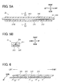
- the optical fiber unit 21 has the optical fiber 211, a stress concentrating plate 212 and a silicone resin body 213.
- the optical fiber 211 extends in the right and left direction.
- the stress concentrating plate 212 is arranged vertically and extends in the right and left direction closely behind the optical fiber 211.
- the silicone resin body 213 embeds the optical fiber 211 and the stress concentrating plate 212 therein.
- the silicone resin body 213 has a rectangular-shaped vertical cross-section.
- the optical fiber 211 is covered with a rubber tube 214.
- the optical fiber unit 21 is arranged such that a first wall (front wall) 2131 of the silicone resin body 213 contacts the rear wall of the load transmission plate 20 and a second wall (rear wall) 2132 of the silicone resin body 213 contacts the front wall of the bumper reinforcement member 7.
- the silicone resin body 213 can be disposed such that the first wall 2131 contacts the front wall of the bumper reinforcement member 7 and the second wall 2132 contacts the rear wall of the load transmission plate 20.
- a second stress concentrating plate which has a shape similar to that of the stress concentrating plate 212, can be added on the opposite side as the stress concentrating plate 212, with respect to the optical fiber 211.
- rungs 215 (described later) of the stress concentrating plate 212 and the rungs of the second stress concentrating plate are staggered in the right and left direction.
- the structure of the optical fiber unit 21 is not limited to the structure illustrated in Figs. 5A and 5B.
- the stress concentrating plate 212 is formed by punching a thin longitudinal metal plate and has a ladder shape including the plurality of vertical rungs (also referred to as raised portions) 215 at predetermined intervals P in the vehicle right and left direction. Each of the vertical rungs 215 contacts an outer circumferential surface of the rubber tube 214 and extends in the vertical direction.
- the load transmission plate 20 is molded with resin.
- the load transmission plate 20 is arranged in the vertical direction and extends in the right and left direction, between the bumper absorber 12 and the optical fiber unit 21 for transmitting the collision load L from the front bumper 1 to the optical fiber unit 21.
- the optical fiber unit 21 is located between the rear surface of the load transmission plate 20 and the front surface of the bumper reinforcement member 7, and extends in the horizontal direction while contacting an upper half of the front surface of the bumper reinforcement member 7.
- the load transmission plate 20 is made of resin and has a substantially plate shape having rigidity higher than that of the bumper cover 11.
- the load transmission plate 20 has an eave portion 210 and a projection 202.
- the eave portion 210 extends from the upper end of the load transmission plate 20 in a rear direction.
- the projection 202 extends from the lower end of the load transmission plate 20 in the rear direction.
- the rear end of the eave portion 201 bends downward to form a stopper portion.
- a projection 203 extends toward the load transmission plate 20, at a position under the optical fiber unit 21 and above the projection 202.
- the bottom wall of the eave portion 201 contacts the top wall of the bumper reinforcement member 7.
- an upward movement of the load transmission plate 20 is restricted because the projection 203 restricts an upward movement of the projection 202.
- a downward movement of the load transmission plate 20 is restricted because the top wall of the bumper reinforcement member 7 restricts a downward movement of the eave portion 201. Accordingly, vertical movement of the load transmission plate 20 due to vertical vibration of the vehicle body is restricted with respect to the bumper reinforcement member 7.
- the load transmission plate 20 is disposed such that the eave portion 201 is movable in the front and rear direction while sliding along the top wall of the bumper reinforcement member 7. Therefore, the load transmission plate 20 can sufficiently transmit the collision load L to the optical fiber unit 21.
- the load transmission plate 20 is linearly movable in the rearward direction. If the length of the projection 202 in the rearward direction is long and the end of the projection 202 is in contact with the front surface of the bumper reinforcement member 7, the load transmission plate 20 rotates in a clockwise direction about the projection 202 as a rotation center.
- the load transmission plate 20 has the sufficient rigidity so that its deformation due to the collision load L is reduced.
- the collision load L can be applied to a wide area of the longitudinal optical fiber unit 21 while suppressing partial deformation of the optical fiber unit 21.
- the collision load L is transmitted to the optical fiber unit 21 through the load transmission plate 20.
- the collision load L is partly applied to the optical fiber 211 through the rungs 215 of the stress concentrating plate 212 because the silicone resin body 213 and the rubber tube 214 are easily elastically deformable. Therefore, the optical fiber 211 is bent at positions corresponding to the rungs 215 with positive correlation.
- the quantity of light passing through the optical fiber 211 is decreased in accordance with the degree of the bents. Accordingly, in a case that a predetermined quantity of light is introduced to one end of the optical fiber 211 from the light transmitting circuit 214, the quantity of light transmitted to the light receiving circuit 25 from the opposite end of the optical fiber 211 correlates to the collision load. With this, the output signal from the light receiving circuit 25 changes with the intensity of the collision load.
- the output of the light receiving circuit 25 is amplified and converted into the digital signal in the signal processing circuit 26. Then, the digital signal is compared to a predetermined threshold value in the determination circuit 27. Also in the determination circuit 27, the collision of the pedestrian is determined in the determination circuit 27 based on the compared result. When the collision of the pedestrian is determined, the pedestrian protection control unit 3 instructs the pillar air bag expansion device 4 to expand the pillar air bag 5.
- the determination of the pedestrian based on the collision load can be made by using a map having multiple-threshold values.
- the determination circuit 27 can be constructed of a hardware circuit such as a comparator. In this case, the A/D converter can be omitted.
- the optical fiber sensor 23 is shipped in a condition fixed to the load transmission plate 20, as shown in Fig. 7.
- a unit in which the optical fiber sensor 23 and the load transmission plate 20 are integrated is referred to as a sensor assembly 100.
- the sensor assembly 100 or the optical fiber sensor 23 may include the signal processing circuit 26 and the determination circuit 27.
- the testing device includes a bed (stage) 109, a pair of side member equivalent parts 108, a bumper reinforcement member equivalent part 107, a front bumper equivalent part 101, a load applying device 120 and an auxiliary device (not shown) for operating the load applying device 120.
- the pair of side member equivalent parts 108 extends upward from a top wall of the bed 109.
- the bumper reinforcement member equivalent part 107 is horizontally fixed at the top ends of the side member equivalent parts 108.
- the front bumper equivalent part 101 is arranged above the bumper reinforcement member equivalent part 107.
- the load applying device 120 is located above the front bumper equivalent part 101.
- the pair of side member equivalent parts 108 has a shape, a quality of material, and an arrangement same as those of the side members 8 of the actual vehicle.
- the actual bumper reinforcement member 7 and the actual front bumper 1 are used as the bumper reinforcement member equivalent part 107 and the front bumper equivalent part 101 to provide the same mechanical property.
- the front bumper equivalent part 101 includes a bumper cover equivalent part 111 and a bumper absorber equivalent part 112.
- the front bumper equivalent part 101 is arranged such that its front face, which faces a front side when actually mounted to the vehicle, faces upward.
- the side member equivalent parts 108 can be arranged to extend in a horizontal direction from a side wall of the bed 109, as in a manner actually mounted to the vehicle.
- the front bumper equivalent part 101 is arranged such that the front face faces in the horizontal direction.
- the load applying device 120 has a frame 121, a sliding rod 122, a load roller 123 and a cylinder (not shown).
- the frame 121 is formed with a through hole 121 a having a length in a direction perpendicular to the frame 121.
- the sliding rod 122 is received in the through hole 121 a with a clearance.
- the load roller 123 is held at the bottom end of the sliding rod 122 to be rotatable.
- the frame 121 is supported by the cylinder to be linearly movable in the horizontal direction.
- a flange is formed at the top end of the sliding rod 122, for restricting the sliding rod 122 from separating from the frame 122.
- the total weight of the sliding rod 122 and the load roller 123 is adjusted to a value in which a weight affected by the gravity of the front bumper equivalent part 101 is slightly subtracted from the test load to be applied to the sensor assembly 100. Because the weight of the front bumper equivalent part 101 is applied to the front surface of the sensor assembly 100, it is noted that the effect at the testing point is limited.
- the bumper reinforcement member equivalent part 101 is lifted for example by using a non-illustrated moving cylinder. Then, the sensor assembly 100 to be tested is set on the bumper reinforcement member equivalent part 107.
- the front bumper equivalent part 101 is moved down and placed on the sensor assembly 100.
- a rod end of the non-illustrated moving cylinder separates downwardly from the front bumper equivalent part 101. Accordingly, only the weight of the front bumper equivalent part 101 is applied to the sensor assembly 100.
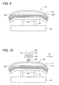
- the frame 121 of the load applying device 120 is linearly moved in a horizontal direction shown by an arrow A1 in Fig. 10.
- the load roller 123 is first placed on one end (left end in Fig. 10) of the top wall (front wall when mounted on the vehicle) of the front bumper equivalent part 101.
- the test load is applied to the left end of the sensor assembly by the weight of the load applying device 120 and the front bumper equivalent part 101.
- the sensor assembly 100 is operated.
- the light is introduced in the optical fiber 211, and the signal voltage from the light receiving circuit 25 is read. This operation is repeated while moving the load applying device 120 in the longitudinal direction A1 of the front bumper equivalent part 101.
- the top wall of the front bumper equivalent part 101 curves at the right and left ends thereof. Because the load roller 123 is guided to be movable in the up and down direction through the sliding rod 122, it moves to follow the curved shape of the front bumper equivalent part 101.
- the test load is applied by using the load roller 123 that is moved in the longitudinal direction of the front bumper equivalent part 101. Accordingly, the sensitivity the optical fiber unit 21 is detected with a very fine pitch in the longitudinal direction thereof in a short time.
- the test data of the sensor assembly 100 can be used to determine the quality and to adjust the sensitivity of the sensor assembly 100. A large amount of data is continuously collected by employing the load roller 123. Therefore, the time required to,the testing can be significantly saved.
- one of the quantity of light emitted from the light transmitting circuit 24 and an amplification factor of the light receiving circuit 25 can be adjusted based on the plural output signals sequentially obtained.
- the sensitivity can be adjusted by adjusting both of the quantity of light and the amplification factor so that a zero point shift of the output value is compensated. Accordingly, the optical fiber sensors 23 have uniform sensitivity and the zero point shift is reduced.
- the sensitivity adjustment by using the obtained plural output signals can be carried out by various ways.
- the sensitivity can be adjusted such that an average of the output signals is set to a predetermined target value. Further, the sensitivity can be adjusted such that one of a minimum value and a maximum value of each output signal is a predetermined target value.
- the sensitivity of the optical fiber unit 21 is determined by the collision load L and a composed characteristic of a load transmission characteristic of the front bumper 1, a load transmission characteristic of the bumper reinforcement member 7 to the side member, and a load transmission characteristic of the optical fiber unit 2.
- the testing method of the present invention all products can be tested with simple steps in a short time, and the test can be carried out at many positions of the optical fiber unit 21. It is not necessary to mount every collision sensor 2 on a model vehicle that is the same type as a vehicle on which the collision sensor 2 is actually mounted. Also, it is not necessary to carry out a sampling inspection or to reduce the testing points. Therefore, the testing method of the present invention improves reliability of the vehicle collision load sensors to be shipped. Further, by using the test data, it is possible to individually adjust the sensitivity. Therefore, the method enhances yield.
- the front bumper equivalent part 101 is placed such that the front face that faces forward when mounted on the vehicle faces upward.
- the front bumper equivalent part 101 can be arranged in the horizontal direction in the similar manner as mounted on the actual vehicle. In this case, it is not necessary to take the effect of the weight of the front bumper equivalent part 101 into consideration.
- the load is applied in the horizontal direction by using the load roller 123.
- the test load can be applied in another method, e.g., in a conventional method.
- the load applying device 120 is moved in the horizontal direction.
- the bed 109 can be moved in the horizontal direction with respect to the load applying device 120.
- the load roller 123 is supported to be movable in the vertical direction.
- the load roller 123 can be fixed in the vertical direction and the bed 109 can be slightly moved in the vertical direction so that the load is generated at the load roller 123.
- the sensitivity of the longitudinal optical fiber unit 21 is detected with a very fine pith in a short time.
- the above method is exemplary used to test the optical fiber sensor 2 arranged at the front part of the vehicle.
- the above method can be applied to test an optical fiber sensor arranged at a rear part of the vehicle for detecting bumps from a rear side of the vehicle.
- the optical fiber sensor is situated in a condition similar to be arranged at the rear part of the vehicle and the sensitivity of the optical fiber sensor is tested in a manner similar to the example embodiment shown in Figs. 8 to 10.
- the above testing method is not limited to test the optical fiber sensor 23, but can be used to test another collision detecting sensor.
Landscapes
- Physics & Mathematics (AREA)
- General Physics & Mathematics (AREA)
- Force Measurement Appropriate To Specific Purposes (AREA)
- Air Bags (AREA)
Applications Claiming Priority (1)
| Application Number | Priority Date | Filing Date | Title |
|---|---|---|---|
| JP2005107992A JP4237159B2 (ja) | 2005-04-04 | 2005-04-04 | 車両用衝突荷重センサの検査方法 |
Publications (3)
| Publication Number | Publication Date |
|---|---|
| EP1710129A2 true EP1710129A2 (fr) | 2006-10-11 |
| EP1710129A3 EP1710129A3 (fr) | 2008-05-21 |
| EP1710129B1 EP1710129B1 (fr) | 2012-05-30 |
Family
ID=36615661
Family Applications (1)
| Application Number | Title | Priority Date | Filing Date |
|---|---|---|---|
| EP06006785A Ceased EP1710129B1 (fr) | 2005-04-04 | 2006-03-30 | Procédé pour tester un capteur de charge de collision pour véhicule |
Country Status (2)
| Country | Link |
|---|---|
| EP (1) | EP1710129B1 (fr) |
| JP (1) | JP4237159B2 (fr) |
Cited By (8)
| Publication number | Priority date | Publication date | Assignee | Title |
|---|---|---|---|---|
| EP2017137A3 (fr) * | 2007-07-17 | 2010-04-14 | Denso Corporation | Capteur de détection de charge et capteur de détection de collision l'utilisant |
| CN112687173A (zh) * | 2020-12-25 | 2021-04-20 | 安徽机电职业技术学院 | 一种基于主被动安全协同优化的汽车碰撞演示平台 |
| CN113576339A (zh) * | 2021-09-30 | 2021-11-02 | 莱克电气绿能科技(苏州)有限公司 | 一种智能扫地机器人的智能检测装置和方法 |
| CN113692611A (zh) * | 2019-02-20 | 2021-11-23 | 惠曼创新解决方案公司 | 用于在碰撞测试期间检测力的光纤系统 |
| US11709105B2 (en) | 2018-01-24 | 2023-07-25 | Humanetics Innovative Solutions, Inc. | Fiber optic system for detecting forces on and measuring deformation of an anthropomorphic test device |
| US11885699B2 (en) | 2019-02-20 | 2024-01-30 | Humanetics Innovative Solutions, Inc. | Optical fiber system having helical core structure for detecting forces during a collision test |
| US12050098B2 (en) | 2019-02-20 | 2024-07-30 | Humanetics Innovative Solutions, Inc. | Shape sensing system and method for anthropomorphic test devices |
| CN119309828A (zh) * | 2024-11-27 | 2025-01-14 | 青岛华涛汽车模具有限公司 | 一种车辆保险杠检测工装及检测方法 |
Families Citing this family (8)
| Publication number | Priority date | Publication date | Assignee | Title |
|---|---|---|---|---|
| JP5004047B2 (ja) * | 2007-05-29 | 2012-08-22 | ニッタ株式会社 | 圧力分布センサシートの校正用治具 |
| EP3379222B1 (fr) | 2017-03-22 | 2020-12-30 | Methode Electronics Malta Ltd. | Ensemble de capteur à base magnétoélastique |
| US11135882B2 (en) | 2018-02-27 | 2021-10-05 | Methode Electronics, Inc. | Towing systems and methods using magnetic field sensing |
| US11221262B2 (en) | 2018-02-27 | 2022-01-11 | Methode Electronics, Inc. | Towing systems and methods using magnetic field sensing |
| US10670479B2 (en) | 2018-02-27 | 2020-06-02 | Methode Electronics, Inc. | Towing systems and methods using magnetic field sensing |
| US11084342B2 (en) | 2018-02-27 | 2021-08-10 | Methode Electronics, Inc. | Towing systems and methods using magnetic field sensing |
| US11491832B2 (en) | 2018-02-27 | 2022-11-08 | Methode Electronics, Inc. | Towing systems and methods using magnetic field sensing |
| KR102791607B1 (ko) * | 2020-01-14 | 2025-04-08 | 현대자동차주식회사 | 전방 충돌 감지 장치 |
Citations (2)
| Publication number | Priority date | Publication date | Assignee | Title |
|---|---|---|---|---|
| JPH05116592A (ja) | 1991-10-30 | 1993-05-14 | Ishikawajima Harima Heavy Ind Co Ltd | 車体衝突検出装置 |
| JPH07190732A (ja) | 1993-12-27 | 1995-07-28 | Sumitomo Wiring Syst Ltd | 車両用衝突センサ |
Family Cites Families (3)
| Publication number | Priority date | Publication date | Assignee | Title |
|---|---|---|---|---|
| US6561301B1 (en) * | 1998-02-24 | 2003-05-13 | Kabushiki Kaisha Toyota Chuo Kenkyusho | Collision discriminating apparatus for vehicles |
| JP4161258B2 (ja) * | 2003-04-15 | 2008-10-08 | 株式会社デンソー | 車両用衝突物体判別装置 |
| JP4276197B2 (ja) * | 2005-03-15 | 2009-06-10 | 株式会社デンソー | 車両用衝突検出装置 |
-
2005
- 2005-04-04 JP JP2005107992A patent/JP4237159B2/ja not_active Expired - Fee Related
-
2006
- 2006-03-30 EP EP06006785A patent/EP1710129B1/fr not_active Ceased
Patent Citations (2)
| Publication number | Priority date | Publication date | Assignee | Title |
|---|---|---|---|---|
| JPH05116592A (ja) | 1991-10-30 | 1993-05-14 | Ishikawajima Harima Heavy Ind Co Ltd | 車体衝突検出装置 |
| JPH07190732A (ja) | 1993-12-27 | 1995-07-28 | Sumitomo Wiring Syst Ltd | 車両用衝突センサ |
Cited By (9)
| Publication number | Priority date | Publication date | Assignee | Title |
|---|---|---|---|---|
| EP2017137A3 (fr) * | 2007-07-17 | 2010-04-14 | Denso Corporation | Capteur de détection de charge et capteur de détection de collision l'utilisant |
| US11709105B2 (en) | 2018-01-24 | 2023-07-25 | Humanetics Innovative Solutions, Inc. | Fiber optic system for detecting forces on and measuring deformation of an anthropomorphic test device |
| CN113692611A (zh) * | 2019-02-20 | 2021-11-23 | 惠曼创新解决方案公司 | 用于在碰撞测试期间检测力的光纤系统 |
| US11885699B2 (en) | 2019-02-20 | 2024-01-30 | Humanetics Innovative Solutions, Inc. | Optical fiber system having helical core structure for detecting forces during a collision test |
| US12050098B2 (en) | 2019-02-20 | 2024-07-30 | Humanetics Innovative Solutions, Inc. | Shape sensing system and method for anthropomorphic test devices |
| CN112687173A (zh) * | 2020-12-25 | 2021-04-20 | 安徽机电职业技术学院 | 一种基于主被动安全协同优化的汽车碰撞演示平台 |
| CN113576339A (zh) * | 2021-09-30 | 2021-11-02 | 莱克电气绿能科技(苏州)有限公司 | 一种智能扫地机器人的智能检测装置和方法 |
| CN113576339B (zh) * | 2021-09-30 | 2021-12-28 | 莱克电气绿能科技(苏州)有限公司 | 一种智能扫地机器人的智能检测装置和方法 |
| CN119309828A (zh) * | 2024-11-27 | 2025-01-14 | 青岛华涛汽车模具有限公司 | 一种车辆保险杠检测工装及检测方法 |
Also Published As
| Publication number | Publication date |
|---|---|
| JP4237159B2 (ja) | 2009-03-11 |
| EP1710129B1 (fr) | 2012-05-30 |
| JP2006284505A (ja) | 2006-10-19 |
| EP1710129A3 (fr) | 2008-05-21 |
Similar Documents
| Publication | Publication Date | Title |
|---|---|---|
| EP1710129B1 (fr) | Procédé pour tester un capteur de charge de collision pour véhicule | |
| KR101381460B1 (ko) | 고체의 압축 강도의 비-파괴 측정 방법 및 장치 | |
| US8401739B2 (en) | Device for activating a security system in a vehicle | |
| JP4791093B2 (ja) | 乗客コンベアの診断装置 | |
| US20070164574A1 (en) | Collision obstacle discrimination device | |
| US9268061B2 (en) | Method for calibrating or testing a detector surface of a device for detecting hydrometeors and a calibration and testing device | |
| US7231803B2 (en) | Hybrid impact sensor | |
| JP2006111053A (ja) | 車両用ワイヤ式衝突検出装置 | |
| US7424179B2 (en) | Collision detecting apparatus for vehicle | |
| US7359818B2 (en) | Sensor apparatus, control system having the same and offset correction method | |
| EP1702812B1 (fr) | Dispositif de détection de collision pour véhicule | |
| US20070084128A1 (en) | Restraint system for vehicle occupants | |
| KR20080059979A (ko) | 자동문의 작용력 측정장치 | |
| KR101625098B1 (ko) | 휴대폰 카메라의 액츄에이터 측정시스템 | |
| US20090088921A1 (en) | Module for detecting a vehicle crash and an airbag deploying system including the same | |
| EP1726491B1 (fr) | Dispositif de détection de collision pour véhicule | |
| EP1702809B1 (fr) | Dispositif de détection de collision pour véhicules | |
| CN1038622C (zh) | 用于火情的早期检测的火警系统 | |
| JP4222872B2 (ja) | タイヤ接地踏面観察装置 | |
| CN108387308B (zh) | 变速箱啸叫下线检测方法及其检测系统 | |
| US7359779B2 (en) | Method for the evaluation of the mounting location of an acceleration sensor component in a vehicle | |
| JPH0815093A (ja) | ヘッドライトの検査装置 | |
| KR20200075884A (ko) | 음향 계측 시스템 및 파라미터 생성 장치 | |
| KR101837732B1 (ko) | 고속 축중기 및 이를 이용한 고속 축중 검출시스템 | |
| KR101742620B1 (ko) | 휴대폰 카메라의 액츄에이터 측정시스템 |
Legal Events
| Date | Code | Title | Description |
|---|---|---|---|
| PUAI | Public reference made under article 153(3) epc to a published international application that has entered the european phase |
Free format text: ORIGINAL CODE: 0009012 |
|
| AK | Designated contracting states |
Kind code of ref document: A2 Designated state(s): AT BE BG CH CY CZ DE DK EE ES FI FR GB GR HU IE IS IT LI LT LU LV MC NL PL PT RO SE SI SK TR |
|
| AX | Request for extension of the european patent |
Extension state: AL BA HR MK YU |
|
| PUAL | Search report despatched |
Free format text: ORIGINAL CODE: 0009013 |
|
| AK | Designated contracting states |
Kind code of ref document: A3 Designated state(s): AT BE BG CH CY CZ DE DK EE ES FI FR GB GR HU IE IS IT LI LT LU LV MC NL PL PT RO SE SI SK TR |
|
| AX | Request for extension of the european patent |
Extension state: AL BA HR MK YU |
|
| RIC1 | Information provided on ipc code assigned before grant |
Ipc: B60R 21/0136 20060101AFI20080417BHEP Ipc: B60R 19/48 20060101ALN20080417BHEP Ipc: G01R 31/28 20060101ALI20080417BHEP Ipc: B60R 21/01 20060101ALN20080417BHEP Ipc: B60R 21/34 20060101ALN20080417BHEP |
|
| 17P | Request for examination filed |
Effective date: 20080911 |
|
| AKX | Designation fees paid |
Designated state(s): DE FR GB IT SE |
|
| 17Q | First examination report despatched |
Effective date: 20091124 |
|
| GRAP | Despatch of communication of intention to grant a patent |
Free format text: ORIGINAL CODE: EPIDOSNIGR1 |
|
| RIN1 | Information on inventor provided before grant (corrected) |
Inventor name: KOBAYASHI, SHIGENORI,C/O DENSO CORPORATION Inventor name: OTAKA, KOJI,C/O DENSO CORPORATION Inventor name: NAKAGAWA, YUKIOC/O TOYOTA JIDOSHA KABUSHIKI KAISHA Inventor name: SAITO, TAKAHIRO,C/O HITACHI CABLE, LTD. Inventor name: IYODA, MOTOMIC/O TOYOTA JIDOSHA KABUSHIKI KAISHA Inventor name: HISHIDA, YASUYUKI,C/O HITACHI CABLE, LTD. |
|
| GRAS | Grant fee paid |
Free format text: ORIGINAL CODE: EPIDOSNIGR3 |
|
| GRAA | (expected) grant |
Free format text: ORIGINAL CODE: 0009210 |
|
| AK | Designated contracting states |
Kind code of ref document: B1 Designated state(s): DE FR GB IT SE |
|
| REG | Reference to a national code |
Ref country code: GB Ref legal event code: FG4D |
|
| REG | Reference to a national code |
Ref country code: SE Ref legal event code: TRGR |
|
| REG | Reference to a national code |
Ref country code: DE Ref legal event code: R096 Ref document number: 602006029757 Country of ref document: DE Effective date: 20120726 |
|
| RAP2 | Party data changed (patent owner data changed or rights of a patent transferred) |
Owner name: DENSO CORPORATION Owner name: TOYOTA JIDOSHA KABUSHIKI KAISHA |
|
| PLBE | No opposition filed within time limit |
Free format text: ORIGINAL CODE: 0009261 |
|
| STAA | Information on the status of an ep patent application or granted ep patent |
Free format text: STATUS: NO OPPOSITION FILED WITHIN TIME LIMIT |
|
| 26N | No opposition filed |
Effective date: 20130301 |
|
| REG | Reference to a national code |
Ref country code: DE Ref legal event code: R097 Ref document number: 602006029757 Country of ref document: DE Effective date: 20130301 |
|
| REG | Reference to a national code |
Ref country code: FR Ref legal event code: PLFP Year of fee payment: 11 |
|
| REG | Reference to a national code |
Ref country code: DE Ref legal event code: R084 Ref document number: 602006029757 Country of ref document: DE |
|
| REG | Reference to a national code |
Ref country code: GB Ref legal event code: 746 Effective date: 20161103 |
|
| REG | Reference to a national code |
Ref country code: FR Ref legal event code: PLFP Year of fee payment: 12 |
|
| PGFP | Annual fee paid to national office [announced via postgrant information from national office to epo] |
Ref country code: FR Payment date: 20170322 Year of fee payment: 12 Ref country code: SE Payment date: 20170321 Year of fee payment: 12 |
|
| PGFP | Annual fee paid to national office [announced via postgrant information from national office to epo] |
Ref country code: GB Payment date: 20170322 Year of fee payment: 12 |
|
| PGFP | Annual fee paid to national office [announced via postgrant information from national office to epo] |
Ref country code: DE Payment date: 20170322 Year of fee payment: 12 |
|
| PGFP | Annual fee paid to national office [announced via postgrant information from national office to epo] |
Ref country code: IT Payment date: 20170323 Year of fee payment: 12 |
|
| REG | Reference to a national code |
Ref country code: DE Ref legal event code: R119 Ref document number: 602006029757 Country of ref document: DE |
|
| PG25 | Lapsed in a contracting state [announced via postgrant information from national office to epo] |
Ref country code: SE Free format text: LAPSE BECAUSE OF NON-PAYMENT OF DUE FEES Effective date: 20180331 |
|
| GBPC | Gb: european patent ceased through non-payment of renewal fee |
Effective date: 20180330 |
|
| PG25 | Lapsed in a contracting state [announced via postgrant information from national office to epo] |
Ref country code: DE Free format text: LAPSE BECAUSE OF NON-PAYMENT OF DUE FEES Effective date: 20181002 |
|
| PG25 | Lapsed in a contracting state [announced via postgrant information from national office to epo] |
Ref country code: IT Free format text: LAPSE BECAUSE OF NON-PAYMENT OF DUE FEES Effective date: 20180330 Ref country code: GB Free format text: LAPSE BECAUSE OF NON-PAYMENT OF DUE FEES Effective date: 20180330 |
|
| PG25 | Lapsed in a contracting state [announced via postgrant information from national office to epo] |
Ref country code: FR Free format text: LAPSE BECAUSE OF NON-PAYMENT OF DUE FEES Effective date: 20180331 |