EP1710143B1 - Kupplungsschlupfschutzvorrichtung - Google Patents
Kupplungsschlupfschutzvorrichtung Download PDFInfo
- Publication number
- EP1710143B1 EP1710143B1 EP05102764A EP05102764A EP1710143B1 EP 1710143 B1 EP1710143 B1 EP 1710143B1 EP 05102764 A EP05102764 A EP 05102764A EP 05102764 A EP05102764 A EP 05102764A EP 1710143 B1 EP1710143 B1 EP 1710143B1
- Authority
- EP
- European Patent Office
- Prior art keywords
- engine torque
- gear ratio
- clutch slip
- ratio value
- torque level
- Prior art date
- Legal status (The legal status is an assumption and is not a legal conclusion. Google has not performed a legal analysis and makes no representation as to the accuracy of the status listed.)
- Expired - Lifetime
Links
Images


Classifications
-
- F—MECHANICAL ENGINEERING; LIGHTING; HEATING; WEAPONS; BLASTING
- F16—ENGINEERING ELEMENTS AND UNITS; GENERAL MEASURES FOR PRODUCING AND MAINTAINING EFFECTIVE FUNCTIONING OF MACHINES OR INSTALLATIONS; THERMAL INSULATION IN GENERAL
- F16D—COUPLINGS FOR TRANSMITTING ROTATION; CLUTCHES; BRAKES
- F16D48/00—External control of clutches
- F16D48/06—Control by electric or electronic means, e.g. of fluid pressure
-
- B—PERFORMING OPERATIONS; TRANSPORTING
- B60—VEHICLES IN GENERAL
- B60W—CONJOINT CONTROL OF VEHICLE SUB-UNITS OF DIFFERENT TYPE OR DIFFERENT FUNCTION; CONTROL SYSTEMS SPECIALLY ADAPTED FOR HYBRID VEHICLES; ROAD VEHICLE DRIVE CONTROL SYSTEMS FOR PURPOSES NOT RELATED TO THE CONTROL OF A PARTICULAR SUB-UNIT
- B60W2510/00—Input parameters relating to a particular sub-units
- B60W2510/02—Clutches
- B60W2510/0241—Clutch slip, i.e. difference between input and output speeds
-
- B—PERFORMING OPERATIONS; TRANSPORTING
- B60—VEHICLES IN GENERAL
- B60W—CONJOINT CONTROL OF VEHICLE SUB-UNITS OF DIFFERENT TYPE OR DIFFERENT FUNCTION; CONTROL SYSTEMS SPECIALLY ADAPTED FOR HYBRID VEHICLES; ROAD VEHICLE DRIVE CONTROL SYSTEMS FOR PURPOSES NOT RELATED TO THE CONTROL OF A PARTICULAR SUB-UNIT
- B60W2510/00—Input parameters relating to a particular sub-units
- B60W2510/06—Combustion engines, Gas turbines
- B60W2510/0638—Engine speed
-
- B—PERFORMING OPERATIONS; TRANSPORTING
- B60—VEHICLES IN GENERAL
- B60W—CONJOINT CONTROL OF VEHICLE SUB-UNITS OF DIFFERENT TYPE OR DIFFERENT FUNCTION; CONTROL SYSTEMS SPECIALLY ADAPTED FOR HYBRID VEHICLES; ROAD VEHICLE DRIVE CONTROL SYSTEMS FOR PURPOSES NOT RELATED TO THE CONTROL OF A PARTICULAR SUB-UNIT
- B60W2510/00—Input parameters relating to a particular sub-units
- B60W2510/10—Change speed gearings
- B60W2510/1005—Transmission ratio engaged
-
- B—PERFORMING OPERATIONS; TRANSPORTING
- B60—VEHICLES IN GENERAL
- B60W—CONJOINT CONTROL OF VEHICLE SUB-UNITS OF DIFFERENT TYPE OR DIFFERENT FUNCTION; CONTROL SYSTEMS SPECIALLY ADAPTED FOR HYBRID VEHICLES; ROAD VEHICLE DRIVE CONTROL SYSTEMS FOR PURPOSES NOT RELATED TO THE CONTROL OF A PARTICULAR SUB-UNIT
- B60W2510/00—Input parameters relating to a particular sub-units
- B60W2510/10—Change speed gearings
- B60W2510/104—Output speed
-
- B—PERFORMING OPERATIONS; TRANSPORTING
- B60—VEHICLES IN GENERAL
- B60W—CONJOINT CONTROL OF VEHICLE SUB-UNITS OF DIFFERENT TYPE OR DIFFERENT FUNCTION; CONTROL SYSTEMS SPECIALLY ADAPTED FOR HYBRID VEHICLES; ROAD VEHICLE DRIVE CONTROL SYSTEMS FOR PURPOSES NOT RELATED TO THE CONTROL OF A PARTICULAR SUB-UNIT
- B60W2710/00—Output or target parameters relating to a particular sub-units
- B60W2710/02—Clutches
- B60W2710/025—Clutch slip, i.e. difference between input and output speeds
-
- B—PERFORMING OPERATIONS; TRANSPORTING
- B60—VEHICLES IN GENERAL
- B60W—CONJOINT CONTROL OF VEHICLE SUB-UNITS OF DIFFERENT TYPE OR DIFFERENT FUNCTION; CONTROL SYSTEMS SPECIALLY ADAPTED FOR HYBRID VEHICLES; ROAD VEHICLE DRIVE CONTROL SYSTEMS FOR PURPOSES NOT RELATED TO THE CONTROL OF A PARTICULAR SUB-UNIT
- B60W2710/00—Output or target parameters relating to a particular sub-units
- B60W2710/06—Combustion engines, Gas turbines
- B60W2710/0666—Engine torque
-
- B—PERFORMING OPERATIONS; TRANSPORTING
- B60—VEHICLES IN GENERAL
- B60Y—INDEXING SCHEME RELATING TO ASPECTS CROSS-CUTTING VEHICLE TECHNOLOGY
- B60Y2200/00—Type of vehicle
- B60Y2200/10—Road Vehicles
- B60Y2200/14—Trucks; Load vehicles, Busses
-
- F—MECHANICAL ENGINEERING; LIGHTING; HEATING; WEAPONS; BLASTING
- F16—ENGINEERING ELEMENTS AND UNITS; GENERAL MEASURES FOR PRODUCING AND MAINTAINING EFFECTIVE FUNCTIONING OF MACHINES OR INSTALLATIONS; THERMAL INSULATION IN GENERAL
- F16D—COUPLINGS FOR TRANSMITTING ROTATION; CLUTCHES; BRAKES
- F16D2500/00—External control of clutches by electric or electronic means
- F16D2500/10—System to be controlled
- F16D2500/104—Clutch
- F16D2500/10406—Clutch position
- F16D2500/10412—Transmission line of a vehicle
-
- F—MECHANICAL ENGINEERING; LIGHTING; HEATING; WEAPONS; BLASTING
- F16—ENGINEERING ELEMENTS AND UNITS; GENERAL MEASURES FOR PRODUCING AND MAINTAINING EFFECTIVE FUNCTIONING OF MACHINES OR INSTALLATIONS; THERMAL INSULATION IN GENERAL
- F16D—COUPLINGS FOR TRANSMITTING ROTATION; CLUTCHES; BRAKES
- F16D2500/00—External control of clutches by electric or electronic means
- F16D2500/10—System to be controlled
- F16D2500/11—Application
- F16D2500/1107—Vehicles
- F16D2500/1112—Heavy vehicle
-
- F—MECHANICAL ENGINEERING; LIGHTING; HEATING; WEAPONS; BLASTING
- F16—ENGINEERING ELEMENTS AND UNITS; GENERAL MEASURES FOR PRODUCING AND MAINTAINING EFFECTIVE FUNCTIONING OF MACHINES OR INSTALLATIONS; THERMAL INSULATION IN GENERAL
- F16D—COUPLINGS FOR TRANSMITTING ROTATION; CLUTCHES; BRAKES
- F16D2500/00—External control of clutches by electric or electronic means
- F16D2500/30—Signal inputs
- F16D2500/304—Signal inputs from the clutch
- F16D2500/30406—Clutch slip
-
- F—MECHANICAL ENGINEERING; LIGHTING; HEATING; WEAPONS; BLASTING
- F16—ENGINEERING ELEMENTS AND UNITS; GENERAL MEASURES FOR PRODUCING AND MAINTAINING EFFECTIVE FUNCTIONING OF MACHINES OR INSTALLATIONS; THERMAL INSULATION IN GENERAL
- F16D—COUPLINGS FOR TRANSMITTING ROTATION; CLUTCHES; BRAKES
- F16D2500/00—External control of clutches by electric or electronic means
- F16D2500/30—Signal inputs
- F16D2500/306—Signal inputs from the engine
- F16D2500/3067—Speed of the engine
-
- F—MECHANICAL ENGINEERING; LIGHTING; HEATING; WEAPONS; BLASTING
- F16—ENGINEERING ELEMENTS AND UNITS; GENERAL MEASURES FOR PRODUCING AND MAINTAINING EFFECTIVE FUNCTIONING OF MACHINES OR INSTALLATIONS; THERMAL INSULATION IN GENERAL
- F16D—COUPLINGS FOR TRANSMITTING ROTATION; CLUTCHES; BRAKES
- F16D2500/00—External control of clutches by electric or electronic means
- F16D2500/30—Signal inputs
- F16D2500/308—Signal inputs from the transmission
- F16D2500/30806—Engaged transmission ratio
- F16D2500/30807—Estimation of the engaged transmission ratio
-
- F—MECHANICAL ENGINEERING; LIGHTING; HEATING; WEAPONS; BLASTING
- F16—ENGINEERING ELEMENTS AND UNITS; GENERAL MEASURES FOR PRODUCING AND MAINTAINING EFFECTIVE FUNCTIONING OF MACHINES OR INSTALLATIONS; THERMAL INSULATION IN GENERAL
- F16D—COUPLINGS FOR TRANSMITTING ROTATION; CLUTCHES; BRAKES
- F16D2500/00—External control of clutches by electric or electronic means
- F16D2500/30—Signal inputs
- F16D2500/308—Signal inputs from the transmission
- F16D2500/3081—Signal inputs from the transmission from the input shaft
- F16D2500/30816—Speed of the input shaft
-
- F—MECHANICAL ENGINEERING; LIGHTING; HEATING; WEAPONS; BLASTING
- F16—ENGINEERING ELEMENTS AND UNITS; GENERAL MEASURES FOR PRODUCING AND MAINTAINING EFFECTIVE FUNCTIONING OF MACHINES OR INSTALLATIONS; THERMAL INSULATION IN GENERAL
- F16D—COUPLINGS FOR TRANSMITTING ROTATION; CLUTCHES; BRAKES
- F16D2500/00—External control of clutches by electric or electronic means
- F16D2500/50—Problem to be solved by the control system
- F16D2500/502—Relating the clutch
- F16D2500/50296—Limit clutch wear
-
- F—MECHANICAL ENGINEERING; LIGHTING; HEATING; WEAPONS; BLASTING
- F16—ENGINEERING ELEMENTS AND UNITS; GENERAL MEASURES FOR PRODUCING AND MAINTAINING EFFECTIVE FUNCTIONING OF MACHINES OR INSTALLATIONS; THERMAL INSULATION IN GENERAL
- F16D—COUPLINGS FOR TRANSMITTING ROTATION; CLUTCHES; BRAKES
- F16D2500/00—External control of clutches by electric or electronic means
- F16D2500/70—Details about the implementation of the control system
- F16D2500/704—Output parameters from the control unit; Target parameters to be controlled
- F16D2500/70422—Clutch parameters
- F16D2500/70426—Clutch slip
-
- F—MECHANICAL ENGINEERING; LIGHTING; HEATING; WEAPONS; BLASTING
- F16—ENGINEERING ELEMENTS AND UNITS; GENERAL MEASURES FOR PRODUCING AND MAINTAINING EFFECTIVE FUNCTIONING OF MACHINES OR INSTALLATIONS; THERMAL INSULATION IN GENERAL
- F16D—COUPLINGS FOR TRANSMITTING ROTATION; CLUTCHES; BRAKES
- F16D2500/00—External control of clutches by electric or electronic means
- F16D2500/70—Details about the implementation of the control system
- F16D2500/704—Output parameters from the control unit; Target parameters to be controlled
- F16D2500/70452—Engine parameters
- F16D2500/70458—Engine torque
Definitions
- the invention generally relates to motor vehicles and, in particular, to a method and arrangement for clutch slip protection for a motor vehicle.
- the invention further relates to a computer program product comprising instructions for bringing a computer to cause steps of such a method, a computer program for executing the clutch slip protection, and an electronic control unit for such a system.
- motor vehicles are equipped with a mechanical friction-gearshift clutch, e.g. of disc type, arranged between the engine, for example, an internal combustion engine, and a mechanical speed-change gear.
- a mechanical friction-gearshift clutch e.g. of disc type, arranged between the engine, for example, an internal combustion engine, and a mechanical speed-change gear.
- clutch wear causes a not negligible extra cost to the vehicle owner, not only in terms of direct costs of clutch replacement and repairs but also because of consequent indirect costs of vehicle standstill.
- Clutch wear is, to a great extent, caused by clutch slip, i.e. the linings of the clutch on the incoming shaft, i.e. the engine shaft, and the outgoing shaft rotate with different speeds.
- US 6 033 342 discloses an arrangement for slip control where the engine torque is reduced during a predetermined period of time including a time interval beyond the end of the slip state has elapsed.
- This arrangement includes a position sensor arranged at the gearshift clutch to detect the engagement position of the clutch, which output is used at determination of clutch slip together with output signals from a speed sensor for detecting engine speed of the engine and a transmission speed sensor detecting the input speed of the speed change gear.
- the transmission speed sensor is changed to a gear position sensor detecting the current gear position of the speed-change gear.
- It yet another object with the invention to provide a method and a system for clutch slip protection that can be used with manually operated gearboxes as well as automated gearboxes.
- the method further comprises the steps of: obtaining a value corresponding to the propeller shaft speed; determining the quotient between the value corresponding to the engine speed and the value corresponding to the propeller shaft speed as a gear ratio value; estimating a gear ratio value of the gear box by substantially continuously calculating the present relationship between the engine speed and the propeller shaft speed; establishing the occurrence or non-occurrence of clutch slip of the clutch utilizing the estimated gear ratio value.
- the system further comprises output shaft speed sensing means arranged to sense the propeller shaft speed, said sensing means being arranged to communicate with the clutch slip protection means, wherein said clutch slip protection means is arranged to obtain a value corresponding to the propeller shaft speed; determine the quotient between the engine speed and the propeller speed as a gear ratio value; and wherein the clutch slip protection means comprises processing means and storing means arranged to store said gear ratio value, wherein said clutch slip protection means is arranged to: substantially continuously calculate the present relationship between the engine speed and the propeller shaft speed to estimate a gear ratio value of the gear box; establish the occurrence or non-occurrence of clutch slip utilizing said estimated gear ratio value.
- a computer program for an electronic control unit of a vehicle comprises program instructions, which when run on the electronic control unit, brings the electronic control unit to cause the steps of the method according to the first aspect of the invention.
- a computer program product comprising computer readable medium and a computer program according to the third aspect, wherein the computer program is stored on the computer readable medium.
- an electronic control unit of a vehicle comprises a storage means comprising a computer program according to the third aspect.
- the invention is based on the idea of handling clutch slip by using signals or information present, i.e. sensors, in the drive train of the vehicle. This is possible since the occurrence of clutch slip is established by estimating a gear ratio value of the gear box.
- the invention discloses advantages in comparison to the solution disclosed in US 6 033 342 , where further sensors along the driveline are required, for example, a gear position sensor detecting the current gear position of the speed-change gear. This is undesirable because it complicates the system.
- Another advantage is that the invention can be implemented in a vehicle substantially without any major modifications of the present control units of the vehicle, which is required when installing the known system since, for example, a gear position sensor detecting the current gear position of the speed-change gear have to be installed.
- a pre-stored gear ratio value representing an actual gear ratio value of said vehicle is selected and compared with the calculated gear ratio value during a first period of time. If the calculated gear ratio value is substantially equal to said selected gear ratio value during said first period of time, the selected gear ratio value is determined to be the present gear ratio value. Thus, it is verified that the estimated or calculated gear ratio is an actual gear ratio. The reliability is increased by performing the comparison during a period of time.
- the engine torque is reduced to a second lower engine torque level, and the actual engine torque is maintained at said at least second lower level during a second predetermined period of time.
- the gear ratio being assumed to be an actual gear ratio is qualified, i.e. whether the gear ratio being identified as an actual gear ratio in fact is an actual gear ratio, and the risk that, even if the estimated present gear ratio is determined to be an actual gear ratio, the estimated gear ratio is a fixed clutch slip corresponding to an actual gear ratio can be significantly reduced.
- this period of time with reduced engine torque also allows the clutch linings to cool down.
- the method of the invention is suitable to realize or implement as a computer program or a computer program product.
- Fig. 1 shows a schematic block representation of the drive train arrangement for a motor vehicle according to an embodiment of the invention.
- Fig. 2 shows a schematic block representation of the drive train arrangement for a motor vehicle according to another embodiment.
- Fig. 3 shows the general principles of the method for clutch slip protection in a vehicle according to the invention.
- Fig. 4 shows an embodiment of the method according to the invention for clutch slip protection.
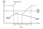
- Fig. 5 shows the principles of the engine torque reduction procedure of the clutch slip protection procedure according to the invention.
- a motor e.g. an internal combustion engine
- a clutch by 2 e.g. a clutch by 3
- a gearbox by 3 e.g. an electric motor
- a speed sensor (detector) 4 arranged to detect the speed of a shaft arranged at the output side of the gearbox 3, for example, the propeller shaft 5 or the output shaft of the gearbox, is connected to a clutch slip protection means 6.
- the slip protection means 6 communicates with engine output adjustment means in the form of an engine control system 9, which is arranged to control the operation of the engine 1.
- the clutch slip protection means 6 is arranged to detect the occurrence of clutch slip and to instruct the engine control system 9 to control the torque of the engine 1 to obtain a cessation of the clutch slip. This will be described in further detail below. Signals from the speed sensor 4 are converted in the protection means 6 to values representing the output shaft's instantaneous angular speed.
- the gearbox output shaft is connected to a final gear 7 which, in turn, is connected to the wheels 8 of the vehicle.
- the slip protection means 6 communicates with engine output adjustment means or an engine control system 9, which is arranged to control the operation of the engine 1.
- An engine speed sensor 10 is arranged to detect the speed of the engine. Signals from the engine speed sensor 10 are converted in the engine control system 9 to instantaneous values thereof. These instantaneous values of the engine speed are communicated with the slip protection means 6 together with signals indicating the engine torque, which in one embodiment is based on the fuel quantity injected.
- the obtained values of the engine speed and the propeller shaft speed are stored in a storing means, in one embodiment, an intermediate memory 11 connected to the slip protection means 6.
- a second storing means or memory 12 connected to the slip protection means 6 is provided with gear ratio values for the various possible gear combinations in the vehicle's gearbox.
- the slip protection means 6 comprises a processor 20 to which a third storing means 21, in addition to the first and second storing means 11 and 12, is connected.
- first and third storing means 12 and 21 or computer readable medium comprises a random access memory (RAM) (not shown) in addition to various non-volatile memories such as read-only memory (ROM) (not shown) and keep-alive memory (KAM) (not shown).
- the read-only third memory comprises a computer program 24 comprising instructions for bringing a computer to cause method steps in accordance with the invention.
- Computer readable medium 21 communicates with processor 20 via a standard control/address bus (not shown).
- computer readable medium may comprise various types of physical devices for temporary and/or persistent storage of data which comprises solid state, magnetic, optical and combination devices.
- the computer readable medium may be implemented using one or more physical devices such as a hard-drive, DRAM, PROMS, EPROMS, EEPROMS, flash memory, and the like.
- the computer readable meadium may also comprises floppy disks, CD ROM, and the like.
- the slip protection means 6 and the engine control system 9 are incorporated within the content of an electronic control unit 25, as shown in Fig. 2 .
- step 30 the gear ratio of the gear box 3 is estimated.
- step 32 it is checked whether clutch slip of the gear box occurs utilizing the estimated gear ratio value. If the occurrence of clutch slip is established, the algorithm proceeds to step 34 where the present engine torque is adjusted or controlled to obtain a cessation of the clutch slip. That is, the processing means 20 is arranged to, at establishment of the occurrence of clutch slip, send a control instruction to the engine control system 9 instructing it to control the present engine torque to obtain cessation of the clutch slip. This control scheme will be described below with reference to Figs. 4 and 5 . On the other hand, if the non-occurrence of clutch slip is established at step 32, the algorithm returns to step 30.
- step 40 the present engine speed is sensed by means of engine speed sensor 10 and the present propeller shaft speed is sensed by means of speed sensor 4.
- step 42 signals from the speed sensor 4 are converted in the slip protection means 6 to values representing the output shaft's instantaneous angular speed and signals from the engine speed sensor 10 are converted in the engine control system 9 to instantaneous values thereof, the values are communicated to the slip protection means 6.
- These instantaneous values of the engine speed are communicated with the slip protection means 6 together with signals indicating the engine torque, which in one embodiment is based on the fuel quantity injected.
- the obtained values of the engine speed and the propeller shaft speed are stored in the intermediate memory 11 connected to the slip protection means 6.
- step 44 the present relationship between the engine speed and the propeller shaft speed is calculated in the slip protection means 6 using the following equation:
- n gearbox is the speed of the propeller shaft and n engine is the engine speed.
- n engine is the engine speed.
- the obtaining of the speed values and the following calculation of the present gearbox ratio can be performed on a continuous basis.
- a gear ratio value of the various possible gear combinations of the gear box 3 stored in the memory 12 being closest to the calculated quotient is collected from the memory 12.
- This collected gear box ratio is estimated to be the present gear box ratio G.
- the gear ratio of the gear box 3 identified to be the next lower gear box ratio in relation to the calculated quotient is set to G, i.e. the present gear box ratio.
- step 48 the occurrence or non occurrence of clutch slip is determined by the following equation:
- non-occurrence of clutch slip is established if ⁇ n is within a range +/- d, where d a predetermined number, and if ⁇ n is not within the range, occurrence of clutch slip is established.
- d is within a range of 50 rpm - 150 rmp.
- step 50 where the present engine torque is collected from the engine control system 9, the engine torque value is stored as the initial engine torque, for example, in storing means 11, and the present engine torque is reduced in accordance with the following equation:
- Mmax M E - K ⁇ n eqt .3
- K is set to a value in the range of 1-3.
- step 52 it is checked whether the estimated present gearbox ratio corresponds to an actual gear ratio of the gearbox 3.
- the reduced engine torque is maintained during a period of time, t 1 , having a predetermined length see Fig. 5 .
- t 1 is a period of time in the range of 0-1.5 seconds. If ⁇ n is within the preset range mentioned above, i.e. the clutch slip is assumed to have stopped, the estimated gear ratio is determined to be an actual gear ratio. If ⁇ n is not within the range, i.e. the clutch slip still exists, the algorithm returns to step 50, where a new engine reduction is calculated in accordance with equation 3 using the present ⁇ n.
- step 54 it is checked whether the gear ratio being assumed to be an actual gear ratio is qualified, i.e. whether the gear ratio being identified as an actual gear ratio in fact is an actual gear ratio. This is due to the fact that, even if the estimated present gear ratio is determined to be an actual gear ratio in step 52, the estimated gear ratio may be a fixed clutch slip corresponding to an actual gear ratio. This check is performed by means of a further reduction of the engine torque, which reduced engine torque is maintained during a second predetermined period of time t 2 , see Fig. 5 . This reduction of the engine torque is small, for example approximately 10-40 Nm.
- This second period of time is approximately 2-20 seconds, and in one embodiment t 2 is set to about 5 seconds. If the gear ratio is maintained substantially during t 2 , the identified gear ratio is verified to be an actual gear ratio, the clutch slip has, accordingly, ceased, and the algorithm proceeds to step 56 where the engine torque is increased. The period of time t 2 also allows the clutch lining to cool down. However, if no in step 54, i.e. the gear ratio is not maintained during the period t 2 , the algorithm returns to step 50.
- the engine torque is ramped up with a predetermined rate per second during a period of time t 3 , which in one embodiment is approximately 10 seconds. In another embodiment, the engine torque is stepped up to the initial engine torque during the period of time t 3 .
- Fig. 5 the principles of the engine torque reduction procedure of the clutch slip protection procedure according to one embodiment of the invention is shown.
- the engine torque is indicated at the vertical axis and time at the horizontal axis.
- ⁇ n is not within the range +/-d and consequently occurrence of clutch slip is established.
- the engine torque is reduced in accordance with equation 3 and the reduced engine torque is maintained during the period of time t 1 .lf the clutch still slipping, the engine torque is reduced a further step in accordance with equation 3. If the clutch slip has ceased, the engine torque is also reduced a step in order to verify that the estimated gear ratio is the actual gear ratio.
- this reduced level is maintained during a period of time t 2 and if the estimated gear ratio is substantially maintained during this period of time the estimated gear ratio is assumed to be an actual gear ratio. Furthermore, the clutch linings are also allowed to cool down during this period of time. Then, the engine torque is increased to the initial engine torque. According to one embodiment of the invention, the engine torque is ramped up with a predetermined rate per second during a period of time t 3 , which in one embodiment is approximately 10 seconds. Finally, at the point of time t 4 the engine torque has reached the initial engine torque.
- the clutch slip stopping function cannot be activated unless at least one preset additional condition is satisfied.
- a first condition may be that the function cannot be activated during a gear shift or during a period of time following the gear shift, which may be within the range of 10-30 seconds.
- a gear shift is defined as a condition where the control system 9 control the engine 1 or when the clutch pedal is pressed during a period of time exceeding t 3 .
- a second condition may be that the velocity of the vehicle must exceed a predetermined velocity V 1 , which may be within the range of 10-30 km/h.
- a third condition may be that the engine torque only can be reduced to a lower limit.
- these additional conditions can be combined arbitrarily.
Landscapes
- Engineering & Computer Science (AREA)
- General Engineering & Computer Science (AREA)
- Physics & Mathematics (AREA)
- Fluid Mechanics (AREA)
- Mechanical Engineering (AREA)
- Hydraulic Clutches, Magnetic Clutches, Fluid Clutches, And Fluid Joints (AREA)
- Mechanical Operated Clutches (AREA)
Claims (25)
- Verfahren zum Schutz vor Kupplungsschlupf in einem von einem Motor (1) angetriebenen Fahrzeug, wobei die Kupplung (2) in einem Drehmomentübertragungspfad des Motors (1) zwischen dem Motor (1) und einem Getriebe (3) angeordnet ist, wobei das Fahrzeug ferner ein Leistungseinstellmittel (9) aufweist, das angeordnet ist, um die Ausgangsleistung des Motors (1) einzustellen, wobei das Verfahren die Schritte umfasst:Erhalten (42) eines Wertes, der der Motordrehzahl des Fahrzeugs entspricht; und dann, wenn das Auftreten von Kupplungsschlupf bestätigt ist, Steuern (34, 50) des gegenwärtigen Motordrehmoments, um eine Beendigung des Kupplungsschlupfes zu erreichen, gekennzeichnet durch die Schritte:Erhalten (42) eines Werts, der der Antriebswellendrehzahl entspricht;Bestimmen (44) des Quotienten zwischen dem Wert, der der Motordrehzahl entspricht, und dem Wert, der der Antriebswellendrehzahl entspricht, als Getriebeübersetzungswert;Schätzen (30, 46) eines Getriebeübersetzungswerts des Getriebes durch im Wesentlichen kontinuierliches Berechnen (44) des gegenwärtigen Verhältnisses zwischen der Motordrehzahl und der Antriebswellendrehzahl;Ermitteln (32, 48) des Auftretens oder des Nicht-Auftretens von Kupplungsschlupf der Kupplung unter Verwendung des geschätzten Getriebeübersetzungswerts.
- Verfahren nach Anspruch 1, wobei der Schritt des Schätzens ferner die Schritte umfasst: Auswählen (46) eines vorab gespeicherten Getriebeübersetzungswertes, der einen aktuellen Getriebeübersetzungswert des Fahrzeugs wiedergibt; Vergleichen (52) des berechneten Getriebeübersetzungswertes mit dem ausgewählten Getriebeübersetzungswert während einer ersten Zeitperiode; und dann, wenn der berechnete Getriebeübersetzungswert im Wesentlichen gleich dem ausgewählten Getriebeübersetzungswert während der ersten Zeitperiode ist, Bestimmen (52) des ausgewählten Getriebeübersetzungswerts als gegenwärtigen Getriebeübersetzungswert.
- Verfahren nach Anspruch 1 oder 2, wobei das Auftreten oder Nicht-Auftreten von Kupplungsschlupf ermittelt wird, wenn △n > d, wobei Δn = |nMotor - nGetriebe *Gl, wobei Δn der Kupplungsschlupf ist, nMotor der Wert entsprechend der Motordrehzahl ist, nGetriebe der Wert entsprechend der Antriebswellendrehzahl ist, d eine vorbestimmte Zahl ist und G der bestimmte gegenwärtige Getriebeübersetzungswert ist.
- Verfahren nach Anspruch 1 bis 3, ferner umfassend die Schritte: dann, wenn das Auftreten von Kupplungsschlupf ermittelt ist (32, 48), Erhalten (50) eines Werts, der dem Motordrehmomentniveau entspricht; und Speichern (50) des Werts, der dem Motordrehmomentniveau entspricht, als Anfangs-Motordrehmomentniveau.
- Verfahren nach Anspruch 1 bis 4, wobei der Schritt des Steuerns die Schritte umfasst: Reduzieren (50) des gegenwärtigen Motordrehmomentniveaus auf ein erstes unteres Motordrehmomentniveau, wobei das erste untere Motordrehmomentniveau auf dem geschätzten Getriebeübersetzungswert basiert; und Aufrechterhalten (52) des ersten unteren Motordrehmoments während einer ersten Zeitperiode.
- Verfahren nach Anspruch 1 bis 5, ferner umfassend den Schritt: Ermitteln (32, 48), ob ein Kupplungsschlupf unter Verwendung des geschätzten Getriebeübersetzungswerts endete.
- Verfahren nach Anspruch 6, wobei der Schritt des Ermittelns, ob Kupplungsschlupf endete, die Schritte umfasst: dann, wenn der ausgewählte Getriebeübersetzungswert als gegenwärtige Getriebeübersetzung bestimmt wurde, Reduzieren des Motordrehmoments auf ein zweites unteres Motordrehmomentniveau; und Beibehalten (54) des aktuellen Motordrehmoments auf dem wenigstens zweiten unteren Niveau während einer zweiten vorbestimmten Zeitperiode.
- Verfahren nach Anspruch 6 oder 7, ferner umfassend den Schritt: dann, wenn ermittelt wurde, dass der Kupplungsschlupf endete, sukzessives Erhöhen (56) des gegenwärtigen Motordrehmomentniveaus auf das Anfangs-Motordrehmomentniveau.
- Verfahren nach Anspruch 6, ferner umfassend die Schritte: dann, wenn nicht ermittelt wurde, dass der Kupplungsschlupf endete, Reduzieren (50) des gegenwärtigen Motordrehmomentniveaus auf wenigstens ein zweites unteres Motordrehmomentniveau, wobei das erste untere Drehmomentniveau auf dem geschätzten Getriebeübersetzungsverhältniswert basiert; und Beibehalten (52) des zweiten Motordrehmomentniveaus während einer Zeitperiode, die im Wesentlichen gleich der ersten Zeitperiode ist.
- Verfahren nach Anspruch 8, wobei der Schritt des Erhöhens den Schritt umfasst: rampenartiges Erhöhen (56) des aktuellen Motordrehmomentniveaus auf das gespeicherte Anfangs-Motordrehmomentniveau während einer zweiten Zeitperiode.
- Verfahren nach Anspruch 5 bis 10, ferner umfassend den Schritt des Berechnens der unteren Motordrehmomentniveaus gemäß Mmax = ME - KΔn, wobei Mmax das maximal zulässige Motordrehmoment ist, ME ein Wert entsprechend dem aktuellen Motordrehmoment ist, K ein vorbestimmter Reduktionsfaktor ist und △n der berechnete Kupplungsschlupf ist.
- System zum Schutz vor Kupplungsschlupf in einem von einem Motor (1) angetriebenen Fahrzeug, wobei die Kupplung (2) in einem Drehmomentübertragungspfad des Motors (1) zwischen dem Motor (1) und einem Getriebe (3) angeordnet ist, wobei das Fahrzeug ferner ein Leistungseinstellmittel (9) umfasst, das angeordnet ist, um die Ausgangsleistung des Motors (1) einzustellen, wobei das System ein Kupplungsschlupf-Schutzmittel (6) und Motordrehzahlerfassungsmittel (10) umfasst, die angeordnet sind, um die Motordrehzahl des Fahrzeugs zu erfassen, wobei das Kupplungsschlupf-Schutzmittel (6) angeordnet ist, um einen Wert entsprechend der Motordrehzahl des Fahrzeugs zu ermitteln; und um bei Ermittlung des Auftretens von Kupplungsschlupf einen Steuerbefehl an das Leistungseinstellmittel (9) auszusenden, um das gegenwärtige Motordrehmoment zu steuern, um eine Beendigung des Kupplungsschlupfes zu erzielen,
dadurch gekennzeichnet, dass das System Ausgangswellendrehzahl-Erfassungsmittel (4) umfasst, die angeordnet sind, um die Antriebswellendrehzahl zu erfassen, wobei die Erfassungsmittel (4, 10) derart ausgebildet sind, dass sie mit dem Kupplungsschlupf-Schutzmittel (6) kommunizieren, wobei das Kupplungsschlupf-Schutzmittel (6) ausgebildet ist, um einen Wert zu erhalten, der der Antriebswellendrehzahl entspricht; um einen Quotienten zwischen der Motordrehzahl und der Antriebsdrehzahl als Übersetzungsverhältniswert zu bestimmen; und wobei das Kupplungsschlupf-Schutzmittel (6) Verarbeitungsmittel (20) und Speichermittel (12) umfasst, die ausgebildet sind, um den Übersetzungsverhältniswert zu speichern, wobei das Kupplungsschlupf-Schutzmittel ausgebildet ist, um im Wesentlichen kontinuierlich das gegenwärtige Verhältnis zwischen der Motordrehzahl und der Antriebswellendrehzahl zu berechnen, um einen Übersetzungsverhältniswert des Getriebes (3) zu schätzen, und um das Auftreten oder Nicht-Auftreten von Kupplungsschlupf unter Verwendung des geschätzten Übersetzungsverhältniswerts zu ermitteln. - System nach Anspruch 12, wobei das Kupplungsschlupf-Schutzmittel (6) ausgebildet ist, um einen vorab gespeicherten Übersetzungsverhältniswert, der einen aktuellen Übersetzungsverhältniswert des Fahrzeugs repräsentiert, als gegenwärtigen Übersetzungsverhältniswert auszuwählen; um den berechneten Übersetzungsverhältniswert mit dem ausgewählten Übersetzungsverhältniswert während einer ersten Zeitperiode zu vergleichen; und dann, wenn der berechnete Übersetzungsverhältniswert im Wesentlichen gleich dem ausgewählten Übersetzungsverhä!tniswert während der ersten Zeitperiode ist, um den ausgewählten Übersetzungsverhältniswert als gegenwärtigen Übersetzungsverhältniswert zu bestimmen.
- System nach Anspruch 12 oder 13, wobei das Auftreten oder Nicht-Auftreten von Kupplungsschlupf ermittelt wird, wenn Δn > d, wobei Δn = |nMotor - nGetriebe *G|, wobei Δn der Kupplungsschlupf ist, nMotor der Wert ist, der der Motordrehzahl entspricht, nGetriebe der Wert ist, der der Antriebswellendrehzahl entspricht, d eine vorbestimmte Zahl ist und G der vorbestimmte gegenwärtige Übersetzungsverhältniswert ist.
- System nach Anspruch 12 bis 14, wobei das Fahrzeug ferner Erfassungsmittel aufweist, die angeordnet sind, um im Wesentlichen kontinuierlich das gegenwärtige Motordrehzahlniveau zu erfassen, wobei das Kupplungsschlupf-Schutzmittel (6) angeordnet ist, um einen Wert zu erhalten, der dem gegenwärtigen Motordrehzahlniveau entspricht.
- System nach Anspruch 12 bis 15, wobei das Kupplungsschlupf-Schutzmittel (6) angeordnet ist, um einen Steuerbefehl an das Ausgangsleistungs-Einstellmittel (9) auszusenden, um das gegenwärtige Motordrehmoment zu steuern, um das gegenwärtige Motordrehmomentniveau auf ein erstes unteres Motordrehmomentniveau abzusenken, wobei das erste untere Motordrehmomentniveau auf dem geschätzten Übersetzungsverhältniswert basiert; und um das erste untere Motordrehmomentniveau während einer ersten Zeitperiode beizubehalten.
- System nach Anspruch 12 bis 15, wobei das Kupplungsschlupf-Schutzmittel (6) ausgebildet ist, um unter Verwendung des geschätzten Übersetzungsverhältniswerts zu ermitteln, ob der Kupplungsschlupf endete.
- System nach Anspruch 17, wobei das Kupplungsschlupf-Schutzmittel (6) ausgebildet ist, um einen Steuerbefehl an das Leistungs-Einstellmittel (9) auszusenden, um das gegenwärtige Motordrehmoment zu steuern, um: dann, wenn der ausgewählte Übersetzungsverhältniswert als gegenwärtiges Übersetzungsverhältnis bestimmt wurde, das Motordrehmoment auf ein zweites unteres Motordrehmomentniveau zu reduzieren; und um das aktuelle Motordrehmoment auf dem wenigstens einen zweiten unteren Niveau während einer zweiten vorbestimmten Zeitperiode zu halten.
- System nach Anspruch 17 oder 18, wobei das Kupplungsschlupf-Schutzmittel (6) ausgebildet ist, um einen Steuerbefehl an das Leistungs-Einstellmittel (9) zu senden, um das gegenwärtige Motordrehmoment zu steuern, um: dann, wenn ermittelt wurde, dass Kupplungsschlupf endete, sukzessive das aktuelle Motordrehmomentniveau auf das Anfangs-Motordrehmomentniveau anzuheben.
- System nach Anspruch 17, wobei das Kupplungsschlupf-Schutzmittel (6) ausgebildet ist, um einen Steuerbefehl an das Leistungs-Einstellmittel (9) auszusenden, um das gegenwärtige Motordrehmoment zu steuern, um: dann, wenn nicht ermittelt wurde, dass der Kupplungsschlupf endete, das gegenwärtige Motordrehmomentniveau auf wenigstens ein zweites unteres Motordrehmomentniveau abzusenken, wobei das erste untere Motordrehmomentniveau auf dem geschätzten Übersetzungsverhältniswert basiert; und um das zweite Motordrehmomentniveau während einer Zeitp eriode aufrechtzuerhalten, die im Wesentlichen gleich der ersten Zeitperiode ist.
- System nach Anspruch 19, wobei das Kupplungsschlupf-Schutzmittel (6) ausgebildet ist, um einen Steuerbefehl an das Leistungs-Einstellmittel (9) zu senden, um das gegenwärtige Motordrehmoment zu steuern, um das Motordrehmoment durch rampenartiges Erhöhen des aktuellen Motordrehmomentniveaus auf das gespeicherte Anfangs-Motordrehmomentniveau während einer zweiten Zeitperiode zu erhöhen.
- System nach Anspruch 16 bis 21, wobei die unteren Drehmomentniveaus nach Maßgabe von Mmax = ME - KΔn berechnet werden, wobei Mmax das maximal zulässige Motordrehmoment ist, ME ein Wert ist, der dem gegenwärtigen Motordrehmoment entspricht, K ein vorbestimmter Reduktionsfaktor ist, und △n der berechnete Kupplungsschlupf ist.
- Computerprogramm (24) für eine elektronische Steuereinheit (25) eines Fahrzeugs zum Schutz vor Kupplungsschlupf,
dadurch gekennzeichnet, dass das Programm (24) Programmanweisungen aufweist, welches dann, wenn es auf der elektronischen Steuereinheit (25) läuft, die elektronische Steuereinheit (25) dazu veranlasst, die Schritte von einem der Ansprüche 1 bis 11 auszuführen. - Computerprogrammprodukt, umfassend ein computerlesbares Medium (21) und ein Computerprogramm (24) nach Anspruch 23, wobei das Computerprogramm (24) auf dem computerlesbaren Medium (21) gespeichert ist.
- Elektronische Steuereinheit (25) eines Fahrzeugs,
dadurch gekennzeichnet, dass ein Speichermittel (21) der Steuereinheit ein Computerprogramm (24) nach Anspruch 23 umfasst.
Priority Applications (5)
| Application Number | Priority Date | Filing Date | Title |
|---|---|---|---|
| EP05102764A EP1710143B1 (de) | 2005-04-08 | 2005-04-08 | Kupplungsschlupfschutzvorrichtung |
| DE602005005789T DE602005005789T2 (de) | 2005-04-08 | 2005-04-08 | Kupplungsschlupfschutzvorrichtung |
| ES05102764T ES2303183T3 (es) | 2005-04-08 | 2005-04-08 | Dispositivo de proteccion contra el patinaje del embrague. |
| AT05102764T ATE391060T1 (de) | 2005-04-08 | 2005-04-08 | Kupplungsschlupfschutzvorrichtung |
| DK05102764T DK1710143T3 (da) | 2005-04-08 | 2005-04-08 | Beskyttelse mod koblingsskred |
Applications Claiming Priority (1)
| Application Number | Priority Date | Filing Date | Title |
|---|---|---|---|
| EP05102764A EP1710143B1 (de) | 2005-04-08 | 2005-04-08 | Kupplungsschlupfschutzvorrichtung |
Publications (2)
| Publication Number | Publication Date |
|---|---|
| EP1710143A1 EP1710143A1 (de) | 2006-10-11 |
| EP1710143B1 true EP1710143B1 (de) | 2008-04-02 |
Family
ID=34939187
Family Applications (1)
| Application Number | Title | Priority Date | Filing Date |
|---|---|---|---|
| EP05102764A Expired - Lifetime EP1710143B1 (de) | 2005-04-08 | 2005-04-08 | Kupplungsschlupfschutzvorrichtung |
Country Status (5)
| Country | Link |
|---|---|
| EP (1) | EP1710143B1 (de) |
| AT (1) | ATE391060T1 (de) |
| DE (1) | DE602005005789T2 (de) |
| DK (1) | DK1710143T3 (de) |
| ES (1) | ES2303183T3 (de) |
Cited By (1)
| Publication number | Priority date | Publication date | Assignee | Title |
|---|---|---|---|---|
| DE102008046843A1 (de) * | 2008-09-08 | 2010-03-25 | Dr.Ing.H.C.F.Porsche Aktiengesellschaft | Verfahren zur Steuerung eines Verbrennungsmotors in Verbindung mit einer automatisierten Reibungskuppelung als Anfahrelement |
Families Citing this family (5)
| Publication number | Priority date | Publication date | Assignee | Title |
|---|---|---|---|---|
| EP1953061B1 (de) | 2007-01-31 | 2012-08-15 | Yamaha Hatsudoki Kabushiki Kaisha | Fahrzeug mit einem stufenlosen Getriebesystem und einem Regler für die Ermittlung von Fehlern in dem System für die Messung der Geschwindigkeit |
| DE102009041770B4 (de) * | 2009-09-16 | 2021-08-12 | Bayerische Motoren Werke Aktiengesellschaft | Verfahren zur Kupplungsschlupfregelung in Kraftfahrzeugen mit einem Handschaltgetriebe |
| DE102010062399B4 (de) * | 2010-12-03 | 2015-12-10 | Bayerische Motoren Werke Aktiengesellschaft | Verfahren zur Ermittlung und Regelung des an einer geschlossenen Kupplung eines Antriebsstrangs eines Fahrzeug auftretenden Schlupfes |
| DE102013009857B4 (de) * | 2013-06-13 | 2016-01-21 | Audi Ag | Verfahren zum Betreiben einer Kupplung eines Fahrzeugs und Fahrzeug |
| US10919534B2 (en) * | 2016-12-20 | 2021-02-16 | Transmission Cvtcorp Inc. | Slip control method and arrangement for a driveline |
Family Cites Families (3)
| Publication number | Priority date | Publication date | Assignee | Title |
|---|---|---|---|---|
| FR2708530B1 (fr) * | 1993-08-03 | 1997-01-24 | Luk Getriebe Systeme Gmbh | Véhicule équipé d'un embrayage automatique. |
| DE19806497C2 (de) * | 1998-02-17 | 2000-03-16 | Mannesmann Sachs Ag | Antriebsanordnung für ein von einem Verbrennungsmotor angetriebenes Kraftfahrzeug |
| DE19810033A1 (de) * | 1998-03-09 | 1999-09-16 | Mannesmann Sachs Ag | Anordnung zur Überwachung des Verschleißzustandes einer Reibungskupplung |
-
2005
- 2005-04-08 EP EP05102764A patent/EP1710143B1/de not_active Expired - Lifetime
- 2005-04-08 DK DK05102764T patent/DK1710143T3/da active
- 2005-04-08 AT AT05102764T patent/ATE391060T1/de not_active IP Right Cessation
- 2005-04-08 ES ES05102764T patent/ES2303183T3/es not_active Expired - Lifetime
- 2005-04-08 DE DE602005005789T patent/DE602005005789T2/de not_active Expired - Lifetime
Cited By (2)
| Publication number | Priority date | Publication date | Assignee | Title |
|---|---|---|---|---|
| DE102008046843A1 (de) * | 2008-09-08 | 2010-03-25 | Dr.Ing.H.C.F.Porsche Aktiengesellschaft | Verfahren zur Steuerung eines Verbrennungsmotors in Verbindung mit einer automatisierten Reibungskuppelung als Anfahrelement |
| DE102008046843B4 (de) * | 2008-09-08 | 2010-11-04 | Dr. Ing. H.C. F. Porsche Aktiengesellschaft | Verfahren zur Steuerung eines Verbrennungsmotors in Verbindung mit einer automatisierten Reibungskuppelung als Anfahrelement |
Also Published As
| Publication number | Publication date |
|---|---|
| EP1710143A1 (de) | 2006-10-11 |
| DE602005005789D1 (de) | 2008-05-15 |
| DK1710143T3 (da) | 2008-07-07 |
| ES2303183T3 (es) | 2008-08-01 |
| ATE391060T1 (de) | 2008-04-15 |
| DE602005005789T2 (de) | 2009-04-09 |
Similar Documents
| Publication | Publication Date | Title |
|---|---|---|
| EP2516194B1 (de) | Verfahren und system zur fahrzeuggeschwindigkeitssteuerung | |
| US8145398B2 (en) | Method for controlling gear ratio changes in an automatic transmission | |
| EP2507104B1 (de) | Verfahren und system für die geschwindigkeitsregelung eines fahrzeugs | |
| EP2694344B1 (de) | Messung einer strassenneigung | |
| KR20120099229A (ko) | 자동차에서 자동화 주차 브레이크의 작동 방법 | |
| EP1225362A2 (de) | Methode zur Kontrolle der Wärmeentwicklung in einer Kupplung | |
| JP2014520703A (ja) | 車両の走行抵抗の決定 | |
| US10458356B2 (en) | Vehicle control apparatus | |
| US20140257657A1 (en) | Method and system for controlling a power train depending on the temperature of a hydraulic torque converter | |
| US5107430A (en) | Method and a system for controlling traction in motor vehicles with mechanical gearboxes | |
| JP2010525277A (ja) | 車両駆動列の低温始動時保護方法 | |
| EP2085657B1 (de) | Verfahren zum Steuern der Aufnahme bergauf für ein Motorfahrzeug, das mit einem automatischen oder Robotergetriebe ausgestattet ist | |
| US20090312929A1 (en) | Method and device for identifying a passive rolling moment of a motor vehicle | |
| US10330029B2 (en) | Method for a more efficient use of a combustion engine in a vehicle | |
| US6937932B2 (en) | Detecting the clutch state during engine drag torque regulation | |
| CN100584664C (zh) | 自动机动车辆动力传动系统及其控制方法 | |
| US9145968B2 (en) | Device and method for controlling shift in vehicle | |
| EP1710143A1 (de) | Kupplungsschlupfschutzvorrichtung | |
| JP2014508263A (ja) | 接触点適応の必要性を決定する方法およびシステム | |
| EP1710462A1 (de) | Schlupfschutzvorrichtung für eine Kupplung | |
| US6480776B1 (en) | Method and apparatus for controlling an automatic gearbox | |
| US6461273B1 (en) | Automated transmission upshift brake control | |
| US20130046450A1 (en) | Driving resistance-dependent shifting delay | |
| KR20210155021A (ko) | 차량의 크립 토크 제어 장치 및 방법 | |
| KR100939393B1 (ko) | 수동 변속기를 구비한 차량의 속도 및 엔진 회전수를 제어하기 위한 장치 및 방법 |
Legal Events
| Date | Code | Title | Description |
|---|---|---|---|
| PUAI | Public reference made under article 153(3) epc to a published international application that has entered the european phase |
Free format text: ORIGINAL CODE: 0009012 |
|
| AK | Designated contracting states |
Kind code of ref document: A1 Designated state(s): AT BE BG CH CY CZ DE DK EE ES FI FR GB GR HU IE IS IT LI LT LU MC NL PL PT RO SE SI SK TR |
|
| AX | Request for extension of the european patent |
Extension state: AL BA HR LV MK YU |
|
| 17P | Request for examination filed |
Effective date: 20070411 |
|
| AKX | Designation fees paid |
Designated state(s): AT BE BG CH CY CZ DE DK EE ES FI FR GB GR HU IE IS IT LI LT LU MC NL PL PT RO SE SI SK TR |
|
| 17Q | First examination report despatched |
Effective date: 20070605 |
|
| GRAP | Despatch of communication of intention to grant a patent |
Free format text: ORIGINAL CODE: EPIDOSNIGR1 |
|
| RIN1 | Information on inventor provided before grant (corrected) |
Inventor name: JAERGENSTEDT, MATS Inventor name: PETTERSSON, HENRIK |
|
| GRAS | Grant fee paid |
Free format text: ORIGINAL CODE: EPIDOSNIGR3 |
|
| GRAA | (expected) grant |
Free format text: ORIGINAL CODE: 0009210 |
|
| AK | Designated contracting states |
Kind code of ref document: B1 Designated state(s): AT BE BG CH CY CZ DE DK EE ES FI FR GB GR HU IE IS IT LI LT LU MC NL PL PT RO SE SI SK TR |
|
| REG | Reference to a national code |
Ref country code: GB Ref legal event code: FG4D |
|
| REG | Reference to a national code |
Ref country code: IE Ref legal event code: FG4D Ref country code: CH Ref legal event code: EP |
|
| REF | Corresponds to: |
Ref document number: 602005005789 Country of ref document: DE Date of ref document: 20080515 Kind code of ref document: P |
|
| REG | Reference to a national code |
Ref country code: DE Ref legal event code: R096 Ref document number: 602005005789 Country of ref document: DE Effective date: 20080515 |
|
| REG | Reference to a national code |
Ref country code: DK Ref legal event code: T3 |
|
| REG | Reference to a national code |
Ref country code: SE Ref legal event code: TRGR |
|
| REG | Reference to a national code |
Ref country code: ES Ref legal event code: FG2A Ref document number: 2303183 Country of ref document: ES Kind code of ref document: T3 |
|
| PG25 | Lapsed in a contracting state [announced via postgrant information from national office to epo] |
Ref country code: SI Free format text: LAPSE BECAUSE OF FAILURE TO SUBMIT A TRANSLATION OF THE DESCRIPTION OR TO PAY THE FEE WITHIN THE PRESCRIBED TIME-LIMIT Effective date: 20080402 |
|
| PG25 | Lapsed in a contracting state [announced via postgrant information from national office to epo] |
Ref country code: BG Free format text: LAPSE BECAUSE OF FAILURE TO SUBMIT A TRANSLATION OF THE DESCRIPTION OR TO PAY THE FEE WITHIN THE PRESCRIBED TIME-LIMIT Effective date: 20080702 Ref country code: PT Free format text: LAPSE BECAUSE OF FAILURE TO SUBMIT A TRANSLATION OF THE DESCRIPTION OR TO PAY THE FEE WITHIN THE PRESCRIBED TIME-LIMIT Effective date: 20080903 Ref country code: FI Free format text: LAPSE BECAUSE OF FAILURE TO SUBMIT A TRANSLATION OF THE DESCRIPTION OR TO PAY THE FEE WITHIN THE PRESCRIBED TIME-LIMIT Effective date: 20080402 |
|
| PG25 | Lapsed in a contracting state [announced via postgrant information from national office to epo] |
Ref country code: MC Free format text: LAPSE BECAUSE OF NON-PAYMENT OF DUE FEES Effective date: 20080430 Ref country code: AT Free format text: LAPSE BECAUSE OF FAILURE TO SUBMIT A TRANSLATION OF THE DESCRIPTION OR TO PAY THE FEE WITHIN THE PRESCRIBED TIME-LIMIT Effective date: 20080402 Ref country code: PL Free format text: LAPSE BECAUSE OF FAILURE TO SUBMIT A TRANSLATION OF THE DESCRIPTION OR TO PAY THE FEE WITHIN THE PRESCRIBED TIME-LIMIT Effective date: 20080402 |
|
| PG25 | Lapsed in a contracting state [announced via postgrant information from national office to epo] |
Ref country code: IS Free format text: LAPSE BECAUSE OF FAILURE TO SUBMIT A TRANSLATION OF THE DESCRIPTION OR TO PAY THE FEE WITHIN THE PRESCRIBED TIME-LIMIT Effective date: 20080802 |
|
| ET | Fr: translation filed | ||
| PG25 | Lapsed in a contracting state [announced via postgrant information from national office to epo] |
Ref country code: LT Free format text: LAPSE BECAUSE OF FAILURE TO SUBMIT A TRANSLATION OF THE DESCRIPTION OR TO PAY THE FEE WITHIN THE PRESCRIBED TIME-LIMIT Effective date: 20080402 Ref country code: EE Free format text: LAPSE BECAUSE OF FAILURE TO SUBMIT A TRANSLATION OF THE DESCRIPTION OR TO PAY THE FEE WITHIN THE PRESCRIBED TIME-LIMIT Effective date: 20080402 Ref country code: CZ Free format text: LAPSE BECAUSE OF FAILURE TO SUBMIT A TRANSLATION OF THE DESCRIPTION OR TO PAY THE FEE WITHIN THE PRESCRIBED TIME-LIMIT Effective date: 20080402 |
|
| PLBE | No opposition filed within time limit |
Free format text: ORIGINAL CODE: 0009261 |
|
| STAA | Information on the status of an ep patent application or granted ep patent |
Free format text: STATUS: NO OPPOSITION FILED WITHIN TIME LIMIT |
|
| PG25 | Lapsed in a contracting state [announced via postgrant information from national office to epo] |
Ref country code: RO Free format text: LAPSE BECAUSE OF FAILURE TO SUBMIT A TRANSLATION OF THE DESCRIPTION OR TO PAY THE FEE WITHIN THE PRESCRIBED TIME-LIMIT Effective date: 20080402 Ref country code: BE Free format text: LAPSE BECAUSE OF FAILURE TO SUBMIT A TRANSLATION OF THE DESCRIPTION OR TO PAY THE FEE WITHIN THE PRESCRIBED TIME-LIMIT Effective date: 20080402 Ref country code: SK Free format text: LAPSE BECAUSE OF FAILURE TO SUBMIT A TRANSLATION OF THE DESCRIPTION OR TO PAY THE FEE WITHIN THE PRESCRIBED TIME-LIMIT Effective date: 20080402 |
|
| 26N | No opposition filed |
Effective date: 20090106 |
|
| PG25 | Lapsed in a contracting state [announced via postgrant information from national office to epo] |
Ref country code: IE Free format text: LAPSE BECAUSE OF NON-PAYMENT OF DUE FEES Effective date: 20080408 |
|
| REG | Reference to a national code |
Ref country code: DE Ref legal event code: R097 Ref document number: 602005005789 Country of ref document: DE Effective date: 20090106 |
|
| PG25 | Lapsed in a contracting state [announced via postgrant information from national office to epo] |
Ref country code: CY Free format text: LAPSE BECAUSE OF FAILURE TO SUBMIT A TRANSLATION OF THE DESCRIPTION OR TO PAY THE FEE WITHIN THE PRESCRIBED TIME-LIMIT Effective date: 20080402 |
|
| REG | Reference to a national code |
Ref country code: CH Ref legal event code: PL |
|
| PG25 | Lapsed in a contracting state [announced via postgrant information from national office to epo] |
Ref country code: CH Free format text: LAPSE BECAUSE OF NON-PAYMENT OF DUE FEES Effective date: 20090430 Ref country code: LI Free format text: LAPSE BECAUSE OF NON-PAYMENT OF DUE FEES Effective date: 20090430 |
|
| PG25 | Lapsed in a contracting state [announced via postgrant information from national office to epo] |
Ref country code: LU Free format text: LAPSE BECAUSE OF NON-PAYMENT OF DUE FEES Effective date: 20080408 Ref country code: HU Free format text: LAPSE BECAUSE OF FAILURE TO SUBMIT A TRANSLATION OF THE DESCRIPTION OR TO PAY THE FEE WITHIN THE PRESCRIBED TIME-LIMIT Effective date: 20081003 |
|
| PG25 | Lapsed in a contracting state [announced via postgrant information from national office to epo] |
Ref country code: TR Free format text: LAPSE BECAUSE OF FAILURE TO SUBMIT A TRANSLATION OF THE DESCRIPTION OR TO PAY THE FEE WITHIN THE PRESCRIBED TIME-LIMIT Effective date: 20080402 |
|
| PG25 | Lapsed in a contracting state [announced via postgrant information from national office to epo] |
Ref country code: GR Free format text: LAPSE BECAUSE OF FAILURE TO SUBMIT A TRANSLATION OF THE DESCRIPTION OR TO PAY THE FEE WITHIN THE PRESCRIBED TIME-LIMIT Effective date: 20080703 |
|
| PGFP | Annual fee paid to national office [announced via postgrant information from national office to epo] |
Ref country code: DK Payment date: 20120411 Year of fee payment: 8 |
|
| REG | Reference to a national code |
Ref country code: DK Ref legal event code: EBP Effective date: 20130430 |
|
| PG25 | Lapsed in a contracting state [announced via postgrant information from national office to epo] |
Ref country code: DK Free format text: LAPSE BECAUSE OF NON-PAYMENT OF DUE FEES Effective date: 20130430 |
|
| REG | Reference to a national code |
Ref country code: FR Ref legal event code: PLFP Year of fee payment: 12 |
|
| REG | Reference to a national code |
Ref country code: FR Ref legal event code: PLFP Year of fee payment: 13 |
|
| REG | Reference to a national code |
Ref country code: FR Ref legal event code: PLFP Year of fee payment: 14 |
|
| P01 | Opt-out of the competence of the unified patent court (upc) registered |
Effective date: 20230516 |
|
| PGFP | Annual fee paid to national office [announced via postgrant information from national office to epo] |
Ref country code: NL Payment date: 20240315 Year of fee payment: 20 |
|
| PGFP | Annual fee paid to national office [announced via postgrant information from national office to epo] |
Ref country code: GB Payment date: 20240229 Year of fee payment: 20 |
|
| PGFP | Annual fee paid to national office [announced via postgrant information from national office to epo] |
Ref country code: SE Payment date: 20240312 Year of fee payment: 20 Ref country code: IT Payment date: 20240313 Year of fee payment: 20 Ref country code: FR Payment date: 20240308 Year of fee payment: 20 |
|
| PGFP | Annual fee paid to national office [announced via postgrant information from national office to epo] |
Ref country code: DE Payment date: 20240306 Year of fee payment: 20 |
|
| PGFP | Annual fee paid to national office [announced via postgrant information from national office to epo] |
Ref country code: ES Payment date: 20240508 Year of fee payment: 20 |
|
| REG | Reference to a national code |
Ref country code: DE Ref legal event code: R071 Ref document number: 602005005789 Country of ref document: DE |
|
| REG | Reference to a national code |
Ref country code: NL Ref legal event code: MK Effective date: 20250407 |
|
| REG | Reference to a national code |
Ref country code: ES Ref legal event code: FD2A Effective date: 20250425 |
|
| REG | Reference to a national code |
Ref country code: GB Ref legal event code: PE20 Expiry date: 20250407 |
|
| REG | Reference to a national code |
Ref country code: SE Ref legal event code: EUG |
|
| PG25 | Lapsed in a contracting state [announced via postgrant information from national office to epo] |
Ref country code: GB Free format text: LAPSE BECAUSE OF EXPIRATION OF PROTECTION Effective date: 20250407 Ref country code: ES Free format text: LAPSE BECAUSE OF EXPIRATION OF PROTECTION Effective date: 20250409 |