EP1710180B1 - Stoßdämpfendes Modul und Anschlagpuffer, insbesondere für Verladerampen mit solchen Modulen - Google Patents
Stoßdämpfendes Modul und Anschlagpuffer, insbesondere für Verladerampen mit solchen Modulen Download PDFInfo
- Publication number
- EP1710180B1 EP1710180B1 EP06300296A EP06300296A EP1710180B1 EP 1710180 B1 EP1710180 B1 EP 1710180B1 EP 06300296 A EP06300296 A EP 06300296A EP 06300296 A EP06300296 A EP 06300296A EP 1710180 B1 EP1710180 B1 EP 1710180B1
- Authority
- EP
- European Patent Office
- Prior art keywords
- buffer
- damping
- previous
- modules
- elastomer
- Prior art date
- Legal status (The legal status is an assumption and is not a legal conclusion. Google has not performed a legal analysis and makes no representation as to the accuracy of the status listed.)
- Expired - Lifetime
Links
Images



Classifications
-
- F—MECHANICAL ENGINEERING; LIGHTING; HEATING; WEAPONS; BLASTING
- F16—ENGINEERING ELEMENTS AND UNITS; GENERAL MEASURES FOR PRODUCING AND MAINTAINING EFFECTIVE FUNCTIONING OF MACHINES OR INSTALLATIONS; THERMAL INSULATION IN GENERAL
- F16F—SPRINGS; SHOCK-ABSORBERS; MEANS FOR DAMPING VIBRATION
- F16F1/00—Springs
- F16F1/36—Springs made of rubber or other material having high internal friction, e.g. thermoplastic elastomers
- F16F1/42—Springs made of rubber or other material having high internal friction, e.g. thermoplastic elastomers characterised by the mode of stressing
- F16F1/52—Springs made of rubber or other material having high internal friction, e.g. thermoplastic elastomers characterised by the mode of stressing loaded in combined stresses
- F16F1/54—Springs made of rubber or other material having high internal friction, e.g. thermoplastic elastomers characterised by the mode of stressing loaded in combined stresses loaded in compression and shear
-
- B—PERFORMING OPERATIONS; TRANSPORTING
- B65—CONVEYING; PACKING; STORING; HANDLING THIN OR FILAMENTARY MATERIAL
- B65G—TRANSPORT OR STORAGE DEVICES, e.g. CONVEYORS FOR LOADING OR TIPPING, SHOP CONVEYOR SYSTEMS OR PNEUMATIC TUBE CONVEYORS
- B65G69/00—Auxiliary measures taken, or devices used, in connection with loading or unloading
- B65G69/001—Buffers for vehicles at loading stations
-
- F—MECHANICAL ENGINEERING; LIGHTING; HEATING; WEAPONS; BLASTING
- F16—ENGINEERING ELEMENTS AND UNITS; GENERAL MEASURES FOR PRODUCING AND MAINTAINING EFFECTIVE FUNCTIONING OF MACHINES OR INSTALLATIONS; THERMAL INSULATION IN GENERAL
- F16F—SPRINGS; SHOCK-ABSORBERS; MEANS FOR DAMPING VIBRATION
- F16F2226/00—Manufacturing; Treatments
- F16F2226/02—Surface treatments
Definitions
- the invention relates to a bumper or damping device, more particularly intended to be implemented at the loading docks, including heavy goods vehicles, such a stopper being furthermore capable of being mounted at the rear of a trailer, to avoid chassis deformations, likely to occur as a result of such shocks.
- bumpers could also be implemented when it is necessary to absorb at least part of the kinetic energy resulting from a movement, in particular of a vehicle, such as in a garage, in industry railway, or at river or maritime quays, and therefore in port areas.
- the trucks are loaded from the rear.
- the rear of the truck or semi-trailer commonly hits the edge of the loading dock, the latter being traditionally made of concrete.
- It is generally made of a compressible damping material to absorb the impact, and a damping gasket extending at the side facing the dock, and the vehicle, the seal being more compressible than the shock absorber itself.
- a bumper according to the preamble of claim 1 has been proposed in the document DE-A-100 03 744 .
- the present invention aims at an effective solution for protecting the loading docks, but also the chassis of trailers and other trucks, simple to implement, while being a reduced manufacturing cost.
- the profiles are made of metal.
- each module is provided with a positive abutment integral with the external profile and extending perpendicular thereto, and capable of sliding in an orifice formed in the internal section, to bear against the structure to be protected, and thus limit the travel path of the external profile.
- This race is for example fixed at 16 millimeters.
- the damping material consists of a natural or synthetic rubber, and in the latter case an elastomer, typically made of SBR (Synthetic Butadiene Rubber) with a hardness of between 60 and 70 Shore A.
- SBR Synthetic Butadiene Rubber
- a material having an elongation at break in the vicinity of 350% is advantageously used, in addition to a breaking strength of at least 14 MPa.
- Said plates are advantageously anti-corrosion treated.
- the periphery of the stopper thus formed is closed elastically by means of a bellows, respectively fixed to the upper plate and the lower plate, in particular using rivets.
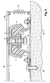
- the upper profile (2) has a substantially planar zone (7), which extends at its two ends by a curved zone (8) capable of remaining substantially parallel to a bent area (9) formed at the lower profile (3).
- This elastomer has a hardness close to 65 ShoreA, a breaking strength of 14 MPa, and an elongation at break of the order of 350%. In any case, a hardness in the range of 60 to 70 Shore A is acceptable, as well as a breaking strength and an elongation at break greater than the values previously indicated, and respectively between 14 and 23 MPa, and 350 and 440%.
- the DRC compression set
- the elastomer is injected between the two sections during the realization of the modules in question.
- the damping module (1) is provided with a means (10), and in particular a nut, secured to the upper profile (2) for example by gluing, oriented perpendicular to its plane region (7), and extending towards the lower profile (3).
- This means (10) is intended to receive a positive stop (25), as described later in connection with the bumper of the invention.
- this means (10) is able to pass through the lower profile (3) at an orifice (11) provided for this purpose within said lower profile.
- the damper module is made such that the rubber or elastomer (6), even in the absence of external stress, therefore of shock, partially passes through said orifice (11), as can be observed well on the figure 1 .
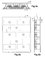
- the bumper of the invention is further described with the Figures 3 to 6 .
- this stop has two plates (21) and (22) parallel to each other. These plates are rigid, and are made of sheet metal, advantageously anti-corrosion treated. Such treatment may result from a high Zn Ni coating.
- the upper platen (22) is significantly thicker than the lower platen (21), due to the fact that it is intended to undergo the full whip shocks that the buffer is intended to damp.
- it may be coated with a colored elastomer layer, so as to confer a certain decorative coherence to all, and better blend into the architecture.
- the lower plate (21) is intended to allow the attachment of the stopper against the structure (20) to be protected, including the vertical face of the loading dock or the rear face of the frame of the trailer or truck.
- the plate (21) is provided with a number of orifices regularly distributed over its surface, allowing the introduction of screws or anchoring system (24) within said structure, said system of anchoring being moreover likely to be completed by chemical anchors, to ensure the durability of the anchoring, in addition to the absence of any movement of said lower plate (21).
- these two plates (21) and (22) are separated from one another, but secured to one another, by means of a plurality of damping modules (1) of the type of those previously described.
- a rubber bellows suitable for closing the inter-platinum space (26), and in particular to prevent the introduction at this level of dust, water and other products may fall from the truck or loading docks, and likely to disrupt the normal operation of the bumper of the invention.
- the distance separating the two plates may be close to ten centimeters.
- This bellows is made of rubber, advantageously treated anti-ultraviolet, to prevent its degradation over time.
- This positive stop (25) is intended, in maximum stroke typically equal to 16 millimeters, to bear against the lower plate (21), and thus limit the potential displacement of the plate (22) relative to the plate (21) .
- Its length is chosen as a function of the tolerable displacement of the outer plate (22) with respect to the lower plate (21) as a function of the rubber (6) used in the dampers (1), in order not to not to end too quickly on the one hand, to its fatigue and its degradation, and on the other hand, to the deformation of the lower section (3) of the modules (1) during a too important displacement of the stopper, then rendering inoperative said stopper.
- the figure 4a corresponds to the absence of charge, therefore shock, the maximum distance between the two plates (21) and (22) being close to 96 mm in the example described.
- the figure 4b represents an intermediate position, in which a shock has begun to occur. It can be seen in (30) a slight creep of the rubber (6) between the two constituent sections of the damping module (1), this creep occurring at the respective bent areas of said profiles.
- the figure 4c represents the maximum load defined by the deflection of the positive stop (25), the latter bearing against the lower plate (21). A greater creep (31) of the rubber (6) is observed.
- the buffer comprises only five damping modules of the type described in relation to the Figures 1 and 2 . These are linearly distributed one below the other, as one can well observe on the figure 5a .
- damping modules (1) are used, divided into three columns, respectively two external columns of three modules and a central column of two modules.
- the characteristics, and in particular the hardness of the damping material, in this case rubber or elastomer, can be adapted according to the intensity of the shocks to be absorbed.
- damping modules By the implementation of such damping modules, loading docks in particular are protected, since no direct impact occurs at their level. Moreover, since a large part of the kinetic energy resulting from the shocks in question is absorbed by the damping material itself, the stresses to which the lower plate and the vertical structure on which it is fastened are largely reduced, allowing to significantly increase the time between two successive rehabilitations of such loading docks, and safeguard the integrity of the chassis of vehicles, including trailer and truck.
- the bumper according to the invention also significantly reduces musculoskeletal disorders.
Landscapes
- Engineering & Computer Science (AREA)
- General Engineering & Computer Science (AREA)
- Mechanical Engineering (AREA)
- Health & Medical Sciences (AREA)
- Child & Adolescent Psychology (AREA)
- Vibration Dampers (AREA)
- Buffer Packaging (AREA)
Claims (10)
- Prellvorrichtung für eine Laderampe oder ein Fahrzeug, zwei starre und zueinander parallele Platten umfassend:- eine untere Platte (21), die dazu bestimmt ist, die Befestigung der Prellvorrichtung an der vertikalen Wand der Rampe oder an der Rückseite des Fahrzeugs herzustellen;- bzw. eine obere oder äußere Platte (22), die dazu bestimmt ist, Stöße direkt aufzunehmen; und wobei die beiden Platten (21, 22) mittels mehrerer Stoßdämpfermodule voneinander getrennt sind,dadurch gekennzeichnet, dass jedes der Stoßdämpfermodule aus zwei starren, teilweise ineinandergesteckten Profilen, einem unteren Profil (3) bzw. einem oberen Profil (2) besteht, die voneinander getrennt und über ein Dämpfungsmaterial (6) fest miteinander verbunden sind, wobei das untere Profil mit Laschen (4) zur Befestigung an der oberen Platte (21) ausgestattet ist, wobei das obere Profil (2) dicker ist als das untere Profil (3), um ihm mehr Steifigkeit zu verleihen, und an der oberen oder äußeren Platte (22) befestigt ist, wobei die Dämpfermodule (1) mehr oder weniger regelmäßig zwischen den Platten verteilt sind, um die betreffenden Stöße mit größtmöglicher Wirksamkeit durch Auffangen der meistmöglichen kinetischen Energie zu dämpfen.
- Prellvorrichtung nach Anspruch 1, dadurch gekennzeichnet, dass jedes Stoßdämpfermodul (1) mit einem positiven Anschlag (10, 25) ausgestattet ist, der fest mit dem oberen Profil (2) verbunden ist und sich in Bezug auf dieses senkrecht erstreckt, und in einer im Inneren des unteren Profils (3) ausgebildeten Öffnung (11) gleiten kann, um an der zu schützenden Struktur oder der unteren Platte (21) in Anlage zu gelangen und somit den möglichen Ausfederungsweg des oberen Profils (2) zu begrenzen.
- Prellvorrichtung nach Anspruch 2, dadurch gekennzeichnet, dass der positive Anschlag (10, 25) die Öffnung (11) mit einer Möglichkeit zu seitlicher Ausfederung durchquert.
- Prellvorrichtung nach Anspruch 3, dadurch gekennzeichnet, dass das Dämpfungsmaterial (6) selbst bei Nichtvorhandensein von Stößen die Öffnung (11) durchquert.
- Prellvorrichtung nach einem der vorhergehenden Ansprüche, dadurch gekennzeichnet, dass das Dämpfungsmaterial (6) aus einem Elastomer besteht, das typischerweise aus SBR (Synthetic Butadiene Rubber, also synthetischem Butadien-Kautschuk) hergestellt ist, dessen Härte zwischen 60 und 70 Shore A beträgt.
- Prellvorrichtung nach einem der vorhergehenden Ansprüche, dadurch gekennzeichnet, dass das Dämpfungsmaterial (6) aus einem Elastomer besteht, das eine Bruchdehnung von mindestens 350% aufweist.
- Prellvorrichtung nach einem der vorhergehenden Ansprüche, dadurch gekennzeichnet, dass das Dämpfungsmaterial (6) aus einem Elastomer besteht, das eine Reißfestigkeit von mindestens 14 MPa aufweist.
- Prellvorrichtung nach einem der vorhergehenden Ansprüche, dadurch gekennzeichnet, dass das Dämpfungsmaterial (6) zwischen dem oberen (2) und unteren (3) Profil eingespritzt ist.
- Prellvorrichtung nach einem der vorhergehenden Ansprüche, dadurch gekennzeichnet, dass ihr Umfang mittels eines Balgs (23) auf elastische Weise verschlossen ist, der an der oberen Platte (22) bzw. der unteren Platte (21) befestigt ist und sich an die Veränderung des die beiden Platten trennenden Raums (26) infolge von Stößen, die die Prellvorrichtung zu dämpfen bestimmt ist, anpassen kann, und dazu geeignet ist, das Eindringen von Wasser und Gegenständen in den Raum zu verhindern.
- Prellvorrichtung nach einem der vorhergehenden Ansprüche, dadurch gekennzeichnet, dass die obere Platte (22) mit einer farbigen Elastomerschicht beschichtet ist.
Applications Claiming Priority (1)
| Application Number | Priority Date | Filing Date | Title |
|---|---|---|---|
| FR0550881A FR2883946B1 (fr) | 2005-04-04 | 2005-04-04 | Module amortisseur de chocs et butoirs, notamment pour quais de chargement mettant en oeuvre de tels modules |
Publications (2)
| Publication Number | Publication Date |
|---|---|
| EP1710180A1 EP1710180A1 (de) | 2006-10-11 |
| EP1710180B1 true EP1710180B1 (de) | 2011-10-05 |
Family
ID=35432525
Family Applications (1)
| Application Number | Title | Priority Date | Filing Date |
|---|---|---|---|
| EP06300296A Expired - Lifetime EP1710180B1 (de) | 2005-04-04 | 2006-03-28 | Stoßdämpfendes Modul und Anschlagpuffer, insbesondere für Verladerampen mit solchen Modulen |
Country Status (3)
| Country | Link |
|---|---|
| EP (1) | EP1710180B1 (de) |
| AT (1) | ATE527195T1 (de) |
| FR (1) | FR2883946B1 (de) |
Families Citing this family (1)
| Publication number | Priority date | Publication date | Assignee | Title |
|---|---|---|---|---|
| CN102849395B (zh) * | 2012-09-28 | 2014-12-03 | 太原重工股份有限公司 | 一种缓冲脚件及具有该缓冲脚件的辊道 |
Citations (1)
| Publication number | Priority date | Publication date | Assignee | Title |
|---|---|---|---|---|
| DE10003744A1 (de) * | 2000-01-28 | 2001-10-11 | Arnold Verladesysteme | Puffereinrichtung für eine LKW-Ladestation |
Family Cites Families (14)
| Publication number | Priority date | Publication date | Assignee | Title |
|---|---|---|---|---|
| US2459741A (en) * | 1942-10-27 | 1949-01-18 | Firestone Tire & Rubber Co | Resilient mounting |
| GB896762A (en) * | 1951-01-16 | 1962-05-16 | Metalastik Ltd | Improvements in or relating to resilient mountings |
| DE1660548U (de) * | 1951-05-15 | 1953-08-06 | Phoenix Metallgummi G M B H | Gummimetallbauteil. |
| DE1684569U (de) * | 1954-07-10 | 1954-10-07 | Suedplastik Und Keramik G M B | Als stossdaempfendes auflager zu verwendender gummimetallbauteil. |
| DE1784505U (de) * | 1955-10-15 | 1959-03-05 | Clemens A Voigt | Elastisches lager fuer motoren, maschinen u. dgl. |
| DE1760439U (de) * | 1955-10-20 | 1958-01-23 | Clemens A Voigt | Elastisches lager. |
| GB904925A (en) * | 1960-06-07 | 1962-09-05 | Metalastik Ltd | Improvements in or relating to anti-vibration mountings |
| DE1206214B (de) * | 1962-08-29 | 1965-12-02 | Continental Gummi Werke Ag | Elastisches Keillager |
| DE1867701U (de) * | 1963-01-03 | 1963-02-21 | Continental Gummi Werke Ag | Elastisches lager. |
| US6141853A (en) * | 1998-12-03 | 2000-11-07 | Miner Enterprises, Inc. | Method of manufacturing and energy absorption apparatus for a railroad car |
| FR2841883B1 (fr) * | 2002-07-08 | 2005-08-26 | Ingeferm | Butoir pour quai |
| WO2004013433A1 (en) | 2002-07-26 | 2004-02-12 | Rite-Hite Holding Corporation | Seal for a loading dock bumper |
| DE502004009875D1 (de) * | 2003-06-25 | 2009-09-24 | Inventio Ag | Befestigungselement für Aufzugsführungsschienen |
| DE10358041B3 (de) * | 2003-12-05 | 2005-05-04 | Deutsche Post Ag | Andockpuffer |
-
2005
- 2005-04-04 FR FR0550881A patent/FR2883946B1/fr not_active Expired - Fee Related
-
2006
- 2006-03-28 EP EP06300296A patent/EP1710180B1/de not_active Expired - Lifetime
- 2006-03-28 AT AT06300296T patent/ATE527195T1/de not_active IP Right Cessation
Patent Citations (1)
| Publication number | Priority date | Publication date | Assignee | Title |
|---|---|---|---|---|
| DE10003744A1 (de) * | 2000-01-28 | 2001-10-11 | Arnold Verladesysteme | Puffereinrichtung für eine LKW-Ladestation |
Also Published As
| Publication number | Publication date |
|---|---|
| FR2883946A1 (fr) | 2006-10-06 |
| ATE527195T1 (de) | 2011-10-15 |
| FR2883946B1 (fr) | 2011-04-01 |
| EP1710180A1 (de) | 2006-10-11 |
Similar Documents
| Publication | Publication Date | Title |
|---|---|---|
| EP1612126B1 (de) | Stossdämpfer für Kraftfahrzeuge | |
| EP0145531B1 (de) | Mittel zum Schützen von Unterstützungskonstruktionen oder dergleichen gegen Stösse | |
| WO2019081830A1 (fr) | Dispositif d'amortissement de choc avant d'un véhicule automobile, comprenant un déflecteur d'air basculant et un amortisseur déformable fixés l'un à l'autre. | |
| FR2842152A1 (fr) | Armature de pare-chocs avec elements absorbeur de chocs perfectionne | |
| EP1710180A1 (de) | Stoßdämpfendes Modul und Anschlagpuffer, insbesondere für Verladerampen mit solchen Modulen | |
| EP0899476B1 (de) | Dämpfungselement, insbesondere zum Lagern der Stützscheibe eines Scheibenwischermechanismusses | |
| EP2911931B1 (de) | Anordnung zur befestigung eines reserveradwanne eines kraftfahrzeugs | |
| EP2431235B1 (de) | Drehbarer Anlegepuffer für Fahrzeug | |
| EP3002159B1 (de) | Stossstangenanordung für kraftfahrzeug, die einen stossdämpfer aus verbundmaterial umfasst | |
| EP1113128B1 (de) | Filterschliessblech für Kraftfahrzeug | |
| FR2812254A1 (fr) | Butoir amortisseur pour vehicule accostant contre un quai | |
| FR2766443A1 (fr) | Dispositif de protection pour reservoir de confinement de matieres et wagon de chemin de fer comportant au moins un tel dispositif | |
| EP1792785B1 (de) | Kraftfahrzeug-Chassis | |
| FR3141414A1 (fr) | Conduit d’air pour face avant de véhicule automobile, face avant de véhicule automobile comportant un tel module et véhicule automobile comportant une telle face avant | |
| WO2023161572A1 (fr) | Pièce de butée optimisée pour un panneau arrière d'un véhicule | |
| FR2932133A1 (fr) | Systeme pour limiter des dommages susceptibles, en cas de choc, d'etre causes par une optique a au moins un organe d'un vehicule automobile | |
| EP3027442B1 (de) | Antriebsstrang für ein kraftfahrzeug | |
| EP2181005B1 (de) | Verbessertes drehbares widerlager für die vorderachse eines automobils | |
| WO2011131879A1 (fr) | Porte de vehicule | |
| FR2958885A1 (fr) | Structure de vehicule automobile pour la fixation et la protection d'un module de refroidissement | |
| EP1700749B1 (de) | Andockpuffer | |
| FR2892079A1 (fr) | Vehicule automobile adapte a l'absorption d'un choc pieton | |
| FR2884783A1 (fr) | Structure de l'avant d'un vehicule automobile | |
| EP1606148B1 (de) | Kotflügel | |
| EP3769979A1 (de) | Kupplungsgelenkanordnung, die ein stossdämpfungssystem umfasst |
Legal Events
| Date | Code | Title | Description |
|---|---|---|---|
| PUAI | Public reference made under article 153(3) epc to a published international application that has entered the european phase |
Free format text: ORIGINAL CODE: 0009012 |
|
| AK | Designated contracting states |
Kind code of ref document: A1 Designated state(s): AT BE BG CH CY CZ DE DK EE ES FI FR GB GR HU IE IS IT LI LT LU LV MC NL PL PT RO SE SI SK TR |
|
| AX | Request for extension of the european patent |
Extension state: AL BA HR MK YU |
|
| 17P | Request for examination filed |
Effective date: 20070208 |
|
| 17Q | First examination report despatched |
Effective date: 20070321 |
|
| AKX | Designation fees paid |
Designated state(s): AT BE BG CH CY CZ DE DK EE ES FI FR GB GR HU IE IS IT LI LT LU LV MC NL PL PT RO SE SI SK TR |
|
| GRAP | Despatch of communication of intention to grant a patent |
Free format text: ORIGINAL CODE: EPIDOSNIGR1 |
|
| GRAS | Grant fee paid |
Free format text: ORIGINAL CODE: EPIDOSNIGR3 |
|
| GRAA | (expected) grant |
Free format text: ORIGINAL CODE: 0009210 |
|
| AK | Designated contracting states |
Kind code of ref document: B1 Designated state(s): AT BE BG CH CY CZ DE DK EE ES FI FR GB GR HU IE IS IT LI LT LU LV MC NL PL PT RO SE SI SK TR |
|
| REG | Reference to a national code |
Ref country code: GB Ref legal event code: FG4D Free format text: NOT ENGLISH |
|
| REG | Reference to a national code |
Ref country code: CH Ref legal event code: EP |
|
| REG | Reference to a national code |
Ref country code: IE Ref legal event code: FG4D |
|
| REG | Reference to a national code |
Ref country code: DE Ref legal event code: R096 Ref document number: 602006024853 Country of ref document: DE Effective date: 20111201 Ref country code: DE Ref legal event code: R082 Ref document number: 602006024853 Country of ref document: DE Representative=s name: MEISSNER, BOLTE & PARTNER GBR, DE Ref country code: DE Ref legal event code: R082 Ref document number: 602006024853 Country of ref document: DE Representative=s name: MEISSNER BOLTE PATENTANWAELTE RECHTSANWAELTE P, DE |
|
| REG | Reference to a national code |
Ref country code: NL Ref legal event code: VDEP Effective date: 20111005 |
|
| PG25 | Lapsed in a contracting state [announced via postgrant information from national office to epo] |
Ref country code: SI Free format text: LAPSE BECAUSE OF FAILURE TO SUBMIT A TRANSLATION OF THE DESCRIPTION OR TO PAY THE FEE WITHIN THE PRESCRIBED TIME-LIMIT Effective date: 20111005 |
|
| LTIE | Lt: invalidation of european patent or patent extension |
Effective date: 20111005 |
|
| REG | Reference to a national code |
Ref country code: AT Ref legal event code: MK05 Ref document number: 527195 Country of ref document: AT Kind code of ref document: T Effective date: 20111005 |
|
| PG25 | Lapsed in a contracting state [announced via postgrant information from national office to epo] |
Ref country code: LT Free format text: LAPSE BECAUSE OF FAILURE TO SUBMIT A TRANSLATION OF THE DESCRIPTION OR TO PAY THE FEE WITHIN THE PRESCRIBED TIME-LIMIT Effective date: 20111005 Ref country code: IS Free format text: LAPSE BECAUSE OF FAILURE TO SUBMIT A TRANSLATION OF THE DESCRIPTION OR TO PAY THE FEE WITHIN THE PRESCRIBED TIME-LIMIT Effective date: 20120205 |
|
| REG | Reference to a national code |
Ref country code: IE Ref legal event code: FD4D |
|
| PG25 | Lapsed in a contracting state [announced via postgrant information from national office to epo] |
Ref country code: NL Free format text: LAPSE BECAUSE OF FAILURE TO SUBMIT A TRANSLATION OF THE DESCRIPTION OR TO PAY THE FEE WITHIN THE PRESCRIBED TIME-LIMIT Effective date: 20111005 Ref country code: LV Free format text: LAPSE BECAUSE OF FAILURE TO SUBMIT A TRANSLATION OF THE DESCRIPTION OR TO PAY THE FEE WITHIN THE PRESCRIBED TIME-LIMIT Effective date: 20111005 Ref country code: SE Free format text: LAPSE BECAUSE OF FAILURE TO SUBMIT A TRANSLATION OF THE DESCRIPTION OR TO PAY THE FEE WITHIN THE PRESCRIBED TIME-LIMIT Effective date: 20111005 Ref country code: GR Free format text: LAPSE BECAUSE OF FAILURE TO SUBMIT A TRANSLATION OF THE DESCRIPTION OR TO PAY THE FEE WITHIN THE PRESCRIBED TIME-LIMIT Effective date: 20120106 Ref country code: PT Free format text: LAPSE BECAUSE OF FAILURE TO SUBMIT A TRANSLATION OF THE DESCRIPTION OR TO PAY THE FEE WITHIN THE PRESCRIBED TIME-LIMIT Effective date: 20120206 |
|
| PG25 | Lapsed in a contracting state [announced via postgrant information from national office to epo] |
Ref country code: CY Free format text: LAPSE BECAUSE OF FAILURE TO SUBMIT A TRANSLATION OF THE DESCRIPTION OR TO PAY THE FEE WITHIN THE PRESCRIBED TIME-LIMIT Effective date: 20111005 |
|
| PG25 | Lapsed in a contracting state [announced via postgrant information from national office to epo] |
Ref country code: IE Free format text: LAPSE BECAUSE OF FAILURE TO SUBMIT A TRANSLATION OF THE DESCRIPTION OR TO PAY THE FEE WITHIN THE PRESCRIBED TIME-LIMIT Effective date: 20111005 Ref country code: BG Free format text: LAPSE BECAUSE OF FAILURE TO SUBMIT A TRANSLATION OF THE DESCRIPTION OR TO PAY THE FEE WITHIN THE PRESCRIBED TIME-LIMIT Effective date: 20120105 Ref country code: EE Free format text: LAPSE BECAUSE OF FAILURE TO SUBMIT A TRANSLATION OF THE DESCRIPTION OR TO PAY THE FEE WITHIN THE PRESCRIBED TIME-LIMIT Effective date: 20111005 Ref country code: SK Free format text: LAPSE BECAUSE OF FAILURE TO SUBMIT A TRANSLATION OF THE DESCRIPTION OR TO PAY THE FEE WITHIN THE PRESCRIBED TIME-LIMIT Effective date: 20111005 Ref country code: DK Free format text: LAPSE BECAUSE OF FAILURE TO SUBMIT A TRANSLATION OF THE DESCRIPTION OR TO PAY THE FEE WITHIN THE PRESCRIBED TIME-LIMIT Effective date: 20111005 Ref country code: CZ Free format text: LAPSE BECAUSE OF FAILURE TO SUBMIT A TRANSLATION OF THE DESCRIPTION OR TO PAY THE FEE WITHIN THE PRESCRIBED TIME-LIMIT Effective date: 20111005 |
|
| PLBE | No opposition filed within time limit |
Free format text: ORIGINAL CODE: 0009261 |
|
| STAA | Information on the status of an ep patent application or granted ep patent |
Free format text: STATUS: NO OPPOSITION FILED WITHIN TIME LIMIT |
|
| PG25 | Lapsed in a contracting state [announced via postgrant information from national office to epo] |
Ref country code: PL Free format text: LAPSE BECAUSE OF FAILURE TO SUBMIT A TRANSLATION OF THE DESCRIPTION OR TO PAY THE FEE WITHIN THE PRESCRIBED TIME-LIMIT Effective date: 20111005 Ref country code: RO Free format text: LAPSE BECAUSE OF FAILURE TO SUBMIT A TRANSLATION OF THE DESCRIPTION OR TO PAY THE FEE WITHIN THE PRESCRIBED TIME-LIMIT Effective date: 20111005 Ref country code: IT Free format text: LAPSE BECAUSE OF FAILURE TO SUBMIT A TRANSLATION OF THE DESCRIPTION OR TO PAY THE FEE WITHIN THE PRESCRIBED TIME-LIMIT Effective date: 20111005 |
|
| 26N | No opposition filed |
Effective date: 20120706 |
|
| PG25 | Lapsed in a contracting state [announced via postgrant information from national office to epo] |
Ref country code: MC Free format text: LAPSE BECAUSE OF NON-PAYMENT OF DUE FEES Effective date: 20120331 |
|
| REG | Reference to a national code |
Ref country code: DE Ref legal event code: R097 Ref document number: 602006024853 Country of ref document: DE Effective date: 20120706 |
|
| GBPC | Gb: european patent ceased through non-payment of renewal fee |
Effective date: 20120328 |
|
| PG25 | Lapsed in a contracting state [announced via postgrant information from national office to epo] |
Ref country code: GB Free format text: LAPSE BECAUSE OF NON-PAYMENT OF DUE FEES Effective date: 20120328 Ref country code: AT Free format text: LAPSE BECAUSE OF FAILURE TO SUBMIT A TRANSLATION OF THE DESCRIPTION OR TO PAY THE FEE WITHIN THE PRESCRIBED TIME-LIMIT Effective date: 20111005 |
|
| PG25 | Lapsed in a contracting state [announced via postgrant information from national office to epo] |
Ref country code: ES Free format text: LAPSE BECAUSE OF FAILURE TO SUBMIT A TRANSLATION OF THE DESCRIPTION OR TO PAY THE FEE WITHIN THE PRESCRIBED TIME-LIMIT Effective date: 20120116 |
|
| PG25 | Lapsed in a contracting state [announced via postgrant information from national office to epo] |
Ref country code: FI Free format text: LAPSE BECAUSE OF FAILURE TO SUBMIT A TRANSLATION OF THE DESCRIPTION OR TO PAY THE FEE WITHIN THE PRESCRIBED TIME-LIMIT Effective date: 20111005 |
|
| PG25 | Lapsed in a contracting state [announced via postgrant information from national office to epo] |
Ref country code: TR Free format text: LAPSE BECAUSE OF FAILURE TO SUBMIT A TRANSLATION OF THE DESCRIPTION OR TO PAY THE FEE WITHIN THE PRESCRIBED TIME-LIMIT Effective date: 20111005 |
|
| PG25 | Lapsed in a contracting state [announced via postgrant information from national office to epo] |
Ref country code: LU Free format text: LAPSE BECAUSE OF NON-PAYMENT OF DUE FEES Effective date: 20120328 |
|
| PG25 | Lapsed in a contracting state [announced via postgrant information from national office to epo] |
Ref country code: HU Free format text: LAPSE BECAUSE OF FAILURE TO SUBMIT A TRANSLATION OF THE DESCRIPTION OR TO PAY THE FEE WITHIN THE PRESCRIBED TIME-LIMIT Effective date: 20060328 |
|
| REG | Reference to a national code |
Ref country code: FR Ref legal event code: PLFP Year of fee payment: 11 |
|
| REG | Reference to a national code |
Ref country code: FR Ref legal event code: PLFP Year of fee payment: 12 |
|
| REG | Reference to a national code |
Ref country code: FR Ref legal event code: PLFP Year of fee payment: 13 |
|
| PGFP | Annual fee paid to national office [announced via postgrant information from national office to epo] |
Ref country code: DE Payment date: 20180309 Year of fee payment: 13 Ref country code: CH Payment date: 20180315 Year of fee payment: 13 |
|
| PGFP | Annual fee paid to national office [announced via postgrant information from national office to epo] |
Ref country code: BE Payment date: 20180327 Year of fee payment: 13 |
|
| PGFP | Annual fee paid to national office [announced via postgrant information from national office to epo] |
Ref country code: FR Payment date: 20190328 Year of fee payment: 14 |
|
| REG | Reference to a national code |
Ref country code: DE Ref legal event code: R119 Ref document number: 602006024853 Country of ref document: DE |
|
| REG | Reference to a national code |
Ref country code: CH Ref legal event code: PL |
|
| REG | Reference to a national code |
Ref country code: BE Ref legal event code: MM Effective date: 20190331 |
|
| PG25 | Lapsed in a contracting state [announced via postgrant information from national office to epo] |
Ref country code: CH Free format text: LAPSE BECAUSE OF NON-PAYMENT OF DUE FEES Effective date: 20190331 Ref country code: LI Free format text: LAPSE BECAUSE OF NON-PAYMENT OF DUE FEES Effective date: 20190331 Ref country code: DE Free format text: LAPSE BECAUSE OF NON-PAYMENT OF DUE FEES Effective date: 20191001 |
|
| PG25 | Lapsed in a contracting state [announced via postgrant information from national office to epo] |
Ref country code: BE Free format text: LAPSE BECAUSE OF NON-PAYMENT OF DUE FEES Effective date: 20190331 |
|
| PG25 | Lapsed in a contracting state [announced via postgrant information from national office to epo] |
Ref country code: FR Free format text: LAPSE BECAUSE OF NON-PAYMENT OF DUE FEES Effective date: 20200331 |