EP1710370A2 - Bande isolante d'extrémité pour chapes de sol - Google Patents
Bande isolante d'extrémité pour chapes de sol Download PDFInfo
- Publication number
- EP1710370A2 EP1710370A2 EP06005844A EP06005844A EP1710370A2 EP 1710370 A2 EP1710370 A2 EP 1710370A2 EP 06005844 A EP06005844 A EP 06005844A EP 06005844 A EP06005844 A EP 06005844A EP 1710370 A2 EP1710370 A2 EP 1710370A2
- Authority
- EP
- European Patent Office
- Prior art keywords
- layer
- insulation strip
- strip according
- edge insulation
- edge
- Prior art date
- Legal status (The legal status is an assumption and is not a legal conclusion. Google has not performed a legal analysis and makes no representation as to the accuracy of the status listed.)
- Withdrawn
Links
- 239000011888 foil Substances 0.000 claims abstract description 16
- 239000004033 plastic Substances 0.000 claims abstract description 9
- 229920003023 plastic Polymers 0.000 claims abstract description 9
- 238000009413 insulation Methods 0.000 claims description 52
- 239000002985 plastic film Substances 0.000 claims description 6
- 229920006255 plastic film Polymers 0.000 claims description 6
- 239000002390 adhesive tape Substances 0.000 claims description 4
- 230000000087 stabilizing effect Effects 0.000 claims description 2
- 239000010410 layer Substances 0.000 description 78
- 210000002414 leg Anatomy 0.000 description 22
- 239000006260 foam Substances 0.000 description 14
- 239000004698 Polyethylene Substances 0.000 description 12
- 239000000463 material Substances 0.000 description 11
- -1 polyethylene Polymers 0.000 description 7
- 229920000573 polyethylene Polymers 0.000 description 6
- 239000007788 liquid Substances 0.000 description 5
- 238000005452 bending Methods 0.000 description 4
- XLYOFNOQVPJJNP-UHFFFAOYSA-N water Substances O XLYOFNOQVPJJNP-UHFFFAOYSA-N 0.000 description 4
- 230000004888 barrier function Effects 0.000 description 3
- 230000015572 biosynthetic process Effects 0.000 description 3
- 239000004743 Polypropylene Substances 0.000 description 2
- PPBRXRYQALVLMV-UHFFFAOYSA-N Styrene Chemical compound C=CC1=CC=CC=C1 PPBRXRYQALVLMV-UHFFFAOYSA-N 0.000 description 2
- 238000010276 construction Methods 0.000 description 2
- 210000003414 extremity Anatomy 0.000 description 2
- 239000003292 glue Substances 0.000 description 2
- 238000004519 manufacturing process Methods 0.000 description 2
- 238000003860 storage Methods 0.000 description 2
- 239000000853 adhesive Substances 0.000 description 1
- 230000001070 adhesive effect Effects 0.000 description 1
- 238000005266 casting Methods 0.000 description 1
- 239000011247 coating layer Substances 0.000 description 1
- 230000001609 comparable effect Effects 0.000 description 1
- 230000003750 conditioning effect Effects 0.000 description 1
- 230000001419 dependent effect Effects 0.000 description 1
- 238000007688 edging Methods 0.000 description 1
- 230000008030 elimination Effects 0.000 description 1
- 238000003379 elimination reaction Methods 0.000 description 1
- 239000000945 filler Substances 0.000 description 1
- 230000002706 hydrostatic effect Effects 0.000 description 1
- 238000012986 modification Methods 0.000 description 1
- 230000004048 modification Effects 0.000 description 1
- 229920001155 polypropylene Polymers 0.000 description 1
- 230000001681 protective effect Effects 0.000 description 1
- 230000000284 resting effect Effects 0.000 description 1
- 238000005096 rolling process Methods 0.000 description 1
- 229920006395 saturated elastomer Polymers 0.000 description 1
- 239000002356 single layer Substances 0.000 description 1
- 230000006641 stabilisation Effects 0.000 description 1
- 238000011105 stabilization Methods 0.000 description 1
- 230000003068 static effect Effects 0.000 description 1
- 230000003746 surface roughness Effects 0.000 description 1
- 210000000689 upper leg Anatomy 0.000 description 1
- 238000009423 ventilation Methods 0.000 description 1
- 238000013022 venting Methods 0.000 description 1
Images

Classifications
-
- E—FIXED CONSTRUCTIONS
- E04—BUILDING
- E04F—FINISHING WORK ON BUILDINGS, e.g. STAIRS, FLOORS
- E04F15/00—Flooring
- E04F15/18—Separately-laid insulating layers; Other additional insulating measures; Floating floors
- E04F15/188—Edge insulation strips, e.g. for floor screed layers
-
- E—FIXED CONSTRUCTIONS
- E04—BUILDING
- E04F—FINISHING WORK ON BUILDINGS, e.g. STAIRS, FLOORS
- E04F15/00—Flooring
- E04F15/12—Flooring or floor layers made of masses in situ, e.g. seamless magnesite floors, terrazzo gypsum floors
- E04F15/14—Construction of joints, e.g. dividing strips
Definitions
- the invention relates to a RanddämmstMail for screed floors, with a multi-layer wall system legs.
- Such edge insulation strips are placed during the casting of screed floors along the edge of the screed surface, that they rest with their Wandstromschenkel to the adjacent wall, and serve to prevent the formation of sound and thermal bridges.
- edge insulation strips made of polyethylene foam are commonly used, which are waterproof by itself and in which with a single layer of material both the necessary thermal insulation properties and the necessary mechanical compliance can be achieved.
- a disadvantage of such edge insulation strips of polyethylene foam or other foamed plastics that they have a relatively high rigidity, which makes it difficult to clean laying in building corners.
- the force formed by the static pressure of the liquid screed is not sufficient to push the edge insulating strip firmly into internal corners.
- the RanddämmstNeill springs back slightly, so that creates an undesirable gap in the corner between two adjoining walls.
- Another disadvantage is that strips of foam plastic manufacturing and storage due to have a certain pre-curvature. This results firstly from a residual curvature after the material has been stored wound on rolls and transported, and secondly from production-related internal stresses, which also lead to a curvature in the transverse direction of the RanddämmstMails, ie to a curvature of the cross section of RanddämmstMails. This latter curvature is particularly disturbing because it causes the edge insulation strip does not fit cleanly against the wall, so that undesirable voids or joints between the edge insulation strip and the wall arise. Again, this disadvantage is particularly serious when used in conjunction with flow screeds.
- the object of the invention is therefore to provide a RanddämmstMake, which has a good moisture resistance and can be laid clean, so that it fits snugly against the wall and can nestle snugly against corners between adjacent walls.
- the Wandstromschenkel has a corset, which is formed by a multilayer plastic film with corrugated cardboard structure, whose shaft is transverse to the longitudinal direction of the RanddämmstMakes.
- the all-plastic corset retains its mechanical strength even in direct contact with liquid screed.
- the corrugated cardboard structure provides the necessary flexibility and thickness compressibility. Due to the running direction of the shaft, the edge insulation strip is relatively rigid in the direction transverse to its longitudinal direction, so that the wall attachment leg rests stable and flat on the wall. In contrast, in its longitudinal direction, the edge insulation strip has a high flexibility, so that it can be rolled up to save space for storage and transport, without leaving behind a significant residual deformation after rolling. In addition, the edge insulation strips can fit snugly on inner and outer corners due to this flexibility.
- the film layers of the corset can with sufficient stability have a small thickness, for example in the order of 10 to 300 microns. so that a material and weight savings is achieved.
- the corset at the same time forms an angled foot of the RanddämmstMails.
- a desired stiffness and straightness of the RanddämmstMails is achieved on straight walls.
- the film material in the region of the foot can be stretched to some extent in the longitudinal direction, so that the edging strip with angled foot can also follow a curved course of the wall and can be laid around outside corners without the foot being cut open got to. Since the foil material of the corset can be stretched in the region of the foot without tearing, the foot remains intact at least in its region immediately adjacent to the wall attachment leg and prevents screed from flowing under the wall attachment leg and coming into direct contact with the wall.
- the wall attachment leg is laminated on at least one side with an insulating layer of foam plastic, for example polyethylene foam, while the foot is formed solely by the corset.
- foam plastic for example polyethylene foam
- the corset can be designed in two layers, with a corrugated foil layer against which a flat top layer rests on one side, which keeps the shape of the corrugations similar to a corrugated board.
- the two film layers may be formed in one piece or welded together at the wave crests, so that no additional adhesive is needed.
- a flat top layer may be applied on both sides of the corrugated layer.
- the corset preferably only faces away from the wall.
- a cover layer while on the opposite side a thin cushion layer of foam plastic, for example polyethylene foam, is laminated directly on the wave crests. This will be the Stabilized shaft and at the same time allows a whopping conditioning of RanddämmstMails on rough surfaces.
- the settlement of the foot relative to the wall attachment leg is facilitated by the fact that the shaft position of the corset and possibly the cushion layer are slit, while the non-slit cover layer forms a continuous liquid barrier.
- a vapor barrier and at the same time a heat mirror can be formed.
- the thicker insulating layer of PE foam is preferably only attached to the wall attachment legs and stands on the angled foot.
- the insulating layer can be kinked, the stabilization achieved by the foot ensures that the edge insulation strip as a whole nestles well into the inner corner.
- the flexibility in internal corners can also be increased by notching the insulation layer in a V-shape.
- the insulating layer can be slit if necessary to increase the flexibility. If necessary, a PE foam filler can be inserted into the gap created by opening up the slot.
- the wall plant leg can be vorgeracecht in the upper area on several parallel to its edge lines by the material is cut from the back, so that the padding layer and the corset are severed and the insulating layer is partially cut. This makes it easier to remove the protruding parts of the wall attachment leg after setting the screed by being torn off at the Vorschw kauungsline. Since the above the lowest Vorschwhariungsline located parts of the Wandstromschenkel have only a relatively small height and also because the flexibility is increased at the Vorschwhariungslinien by the slitting of the insulating layer, the hydrostatic pressure of the liquid screed is sufficient to ensure a snug fit on the wall.
- the foot is glued to an air and water-tight film which forms a base for the flow line. Due to the tight bonding with the also water-impermeable corset of the edge insulation strip to obtain a waterproof "tub" for the flow line. It is particularly advantageous that the wave position in the corset forms ventilation channels in the region of the foot, can escape through the air to the outside, if air bubbles that have formed under the film are struck towards the edge.
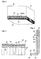
- FIG 1 two rectangular adjacent building walls 10, 12 are shown, which define a bottom surface 14.
- a RanddämmstMail 16 is laid, which abuts with a Wandstromschenkel 18 on the walls 10, 12 and is supported with a right angled foot 20 on the bottom surface 14.
- a corset 24 is shown in Figure 1 for reasons of clarity.
- the corset 24 is formed by a multilayer plastic film such as polypropylene or polyethylene, which has a corrugated cardboard structure.
- the running direction of the shafts 22 is perpendicular to the longitudinal direction of the RanddämmstMails. As a result, the corset is stiffened so that the wall attachment leg 18 clean and flat against the walls 10, 12 rests on the entire height and the foot 20 rests clean and tight on the bottom surface 14.
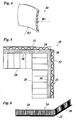
- the structure of the corset of RanddämmstMakes 16 can be seen more clearly in Figures 2 and 3.
- the corset 24 is shown cut in the region of the wall attachment leg 18.
- the waves 22 are formed by a shaft layer 26, the wave crests are fixed on the side facing the foot 20, that is, the Torovaradten from the wall side, by a flat cover layer 28.
- the shaft layer 26 is formed for example by a PP film having a thickness of about 20 to 100 microns, while the cover layer 28, which is claimed in the fixation of the waves essentially only train, have a smaller thickness of, for example, 10 to 20 microns can.
- the cover layer 28 is preferably metallized.
- an insulating layer 30 made of PE foam is attached on wall attachment limb 18, an insulating layer 30 made of PE foam is attached. This is glued, for example, with the cover layer 28 and has a thickness of for example 10 mm, while the corset 24 only has a thickness of about 2 mm.
- a thin cushion layer 32 made of PE foam is attached to the corset 24 on the wall or, the bottom surface facing side of Wandstromschenkels 18 and the foot 20, for example, 1 mm, which additionally stabilizes the shaft layer 26 and also for it ensures that the edge insulation strip adapts well to surface roughness of the walls 10, 12 or the bottom surface 14.
- the corset 24 as well as the insulating layer 30 and the cushion layer 32 may be made of polyethylene, so that a sorted disposal of material residues is made possible.
- the wall attachment limb 18 is preweakened in the vicinity of its upper edge by a plurality of edge-parallel incisions 34 introduced from the rear side. This makes it possible for the screed of the screed to easily remove the protruding parts of the wall attachment leg 18 by demolishing the remaining material bridge of the insulating layer 30 at the level of the respectively desired preweakening line.
- Figure 4 shows a portion of the insulating layer 30 in its natural state prior to attachment to the corset 24. It can be seen that the insulating layer is curved both in cross-section and in the longitudinal direction. The corresponding curves are labeled R1 and R2.
- the vertically extending shafts 20 cause a stiffening, by which the curvature R1 is eliminated.
- the curvature R2 is eliminated at the straight edges of the bottom surface 14 ( Figure 1) by stiffening the edge insulation strip as a whole by the angled foot 20.
- Figure 5 shows in a horizontal section the formation of an inner corner.
- the foot 20 is cut at the inner corner, so that when bending the two separate sections of the foot lie flat over each other.
- the flexibility of the wall attachment leg 18 has been further increased by severing the cushion layer 32 and the corset 24 with the aid of an incision 36 so that they can diverge at the kink.
- the incision 36 is also a bit in the insulating layer 30, so that their flexibility is increased.
- Figure 6 shows the configuration of a RanddämmststMail or a corset 24 thereof in the region of an outer corner. Due to a certain extensibility of the film layers that form the foot 20, this foot does not need to be cut at the kink, but the material can stretch accordingly, the waves 22 diverge like a concertina. This is also possible if the cushion layer 32 is attached to the underside of the foot.
- an insulating layer is provided below the flow-coating layer, which serves as heat and / or impact sound insulation. So that this insulating layer is not impregnated by the flow line, usually laid on the insulating layer, a plastic film on which then the flow line is applied.
- the plastic film should attach to the edge insulation strips in a liquid-tight manner. For this purpose, it is known to glue a Folienscbürze to the edge insulation strips, which in turn can be glued to the laid on the insulation film.
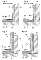
- Figure 7 shows an example of such a RanddämmstMails according to the prior art, which is formed only by an insulating layer 38 made of PE foam with a glued foil skirt 40.
- the insulating layer 38 leans against the wall 10 and stands with its lower edge on the example formed by concrete bottom surface 14.
- a footfall sound insulation 42 is laid, which is covered by a waterproof foil backing 44 for the Fliestrich.
- the foil pad 44 overlaps the resting on the impact sound insulation part of the foil skirt 40 and is glued thereto.
- edge insulation strip 16 With the edge insulation strip 16 according to the invention, these problems can be avoided in an elegant manner. Since in this edge insulating strip 16, the top layer 28 of the corset is also impermeable to water and is not injured when kinking of the foot, they can immediately take over the function of the conventional foil skirt 40. In Figure 9, therefore, the foil pad 44 is directly on the top layer formed by the cover layer 28 of the foot 20 glued. Due to the corrugated cardboard structure of the corset and thus also the foot 20 22 venting channels are formed between the individual waves, through which the air from the air bubbles 46 to the wall 10 can escape, as indicated in Figure 9 by an arrow.
- the waves 22 are not completely, but only partially severed at the kink between Wandstromschenkel and foot, so that they form there material webs 50, which act as tension springs and the Have tendency to pivot the wall attachment leg so that it always rests against the wall 10 under tension.
- the impact sound insulation 42 yields in the manner shown in Figure 10
- the Wandstromschenkel 18 lowers at best somewhat, but is still biased by the force F generated by the material webs 50 against the wall 10.
- the emergence of unwanted cavities can be effectively avoided.
- FIG. 11 shows a top view of an edge insulation strip 16 'according to a further exemplary embodiment.
- This edge insulating strip has, in addition to the insulating layer 30, a further, approximately the same thickness insulating layer 52 made of PE foam on the back of the corset 24.
- the insulating layer 52 is preferably just like the insulating layer 30 only on the wall system legs, but not provided on the foot 20.
- the wall 10 here forms on the one hand an inner corner 54 and on the other hand an outer corner 56 through which the edge insulation strip 16 'passes.
- the insulating layer 52 is severed to achieve sufficient flexibility of RanddämmstMails.
- the continuous insulation layer 30 ensures that there are no sound bridges in the area of the inner corner. On the outside corner 56, conversely, the insulating layer 30 is severed, and the continuous insulating layer 52 also prevents the formation of sound bridges here.
- a piece of double-sided adhesive tape 58 is indicated in FIG. which serves to glue the foot 20 to the foil support 44 according to FIG. In the delivery state, the double-sided adhesive tape 58 is covered by a removable protective strip.
- a corresponding double-sided adhesive tape can also be provided on the underside of the foot 20 so that the edge insulation strip can be bonded to the impact sound insulation 42. As a result, the edge insulation strip is additionally stabilized in particular in the area of the inner and outer corners in its position.
Landscapes
- Engineering & Computer Science (AREA)
- Architecture (AREA)
- Civil Engineering (AREA)
- Structural Engineering (AREA)
- Laminated Bodies (AREA)
- Floor Finish (AREA)
Applications Claiming Priority (2)
| Application Number | Priority Date | Filing Date | Title |
|---|---|---|---|
| DE200520004811 DE202005004811U1 (de) | 2005-03-22 | 2005-03-22 | Randdämmstreifen für Estrichböden |
| DE200520015008 DE202005015008U1 (de) | 2005-09-23 | 2005-09-23 | Randdämmstreifen für Estrichböden |
Publications (2)
| Publication Number | Publication Date |
|---|---|
| EP1710370A2 true EP1710370A2 (fr) | 2006-10-11 |
| EP1710370A3 EP1710370A3 (fr) | 2008-03-12 |
Family
ID=36588720
Family Applications (1)
| Application Number | Title | Priority Date | Filing Date |
|---|---|---|---|
| EP06005844A Withdrawn EP1710370A3 (fr) | 2005-03-22 | 2006-03-22 | Bande isolante d'extrémité pour chapes de sol |
Country Status (1)
| Country | Link |
|---|---|
| EP (1) | EP1710370A3 (fr) |
Cited By (5)
| Publication number | Priority date | Publication date | Assignee | Title |
|---|---|---|---|---|
| DE202007007828U1 (de) | 2007-06-02 | 2008-10-09 | Quithell Kunststofftechnik Gmbh | Dehnungsfugenstreifen für Estrichböden |
| EP2143854A1 (fr) | 2008-07-07 | 2010-01-13 | Quithell Kunststofftechnik GmbH | Bandes de joints de dilatation pour sols en ciment |
| EP2042669A3 (fr) * | 2007-09-28 | 2011-02-16 | Zisola AG Wärme- und Schallisolationen, . | Aide au montage pour bandes de réglage |
| DE202010003965U1 (de) | 2010-03-19 | 2011-08-03 | Quithell Kunststofftechnik Gmbh | Dehnungsfugenstreifen oder Randdämmstreifen |
| EP2913456A1 (fr) * | 2013-12-17 | 2015-09-02 | Kingspan Gefinex GmbH | Procédé de fabrication d'un plancher doté de bandes de rive |
Citations (1)
| Publication number | Priority date | Publication date | Assignee | Title |
|---|---|---|---|---|
| DE3425038C3 (de) | 1984-07-06 | 2000-01-05 | Estrolith Chemische Baustoffe | Randdämmstreifen |
Family Cites Families (6)
| Publication number | Priority date | Publication date | Assignee | Title |
|---|---|---|---|---|
| DE2350400A1 (de) * | 1973-10-08 | 1975-04-10 | Hans Hilgemann | Randdaemmstreifen fuer schwimmende estriche |
| DE3124704A1 (de) * | 1981-06-24 | 1983-01-13 | Josef 5768 Sundern Feische | "belagbahn aus mehreren schichten, insbesondere zum einsatz bei fussbodenheizungen" |
| AT376474B (de) * | 1982-09-10 | 1984-11-26 | Hinteregger Viktor | Randleiste fuer estriche |
| DE3308207A1 (de) * | 1983-03-08 | 1984-09-13 | Gebrüder Kömmerling Kunststoffwerke GmbH, 6780 Pirmasens | Schwimmender estrich |
| DE19722756A1 (de) * | 1997-05-31 | 1998-12-03 | Gefinex Jackon Gmbh | Randdämmstreifen für Estrich |
| DE29714625U1 (de) * | 1997-08-15 | 1997-10-09 | Estrolith - Chemische Baustoffe Wilma Oberst, 71726 Benningen | Randdämmstreifen |
-
2006
- 2006-03-22 EP EP06005844A patent/EP1710370A3/fr not_active Withdrawn
Patent Citations (1)
| Publication number | Priority date | Publication date | Assignee | Title |
|---|---|---|---|---|
| DE3425038C3 (de) | 1984-07-06 | 2000-01-05 | Estrolith Chemische Baustoffe | Randdämmstreifen |
Cited By (6)
| Publication number | Priority date | Publication date | Assignee | Title |
|---|---|---|---|---|
| DE202007007828U1 (de) | 2007-06-02 | 2008-10-09 | Quithell Kunststofftechnik Gmbh | Dehnungsfugenstreifen für Estrichböden |
| EP2042669A3 (fr) * | 2007-09-28 | 2011-02-16 | Zisola AG Wärme- und Schallisolationen, . | Aide au montage pour bandes de réglage |
| EP2143854A1 (fr) | 2008-07-07 | 2010-01-13 | Quithell Kunststofftechnik GmbH | Bandes de joints de dilatation pour sols en ciment |
| DE202010003965U1 (de) | 2010-03-19 | 2011-08-03 | Quithell Kunststofftechnik Gmbh | Dehnungsfugenstreifen oder Randdämmstreifen |
| EP2366849A2 (fr) | 2010-03-19 | 2011-09-21 | Quithell Kunststofftechnik GmbH | Bandes de joints extensibles ou bandes d'isolation de bord |
| EP2913456A1 (fr) * | 2013-12-17 | 2015-09-02 | Kingspan Gefinex GmbH | Procédé de fabrication d'un plancher doté de bandes de rive |
Also Published As
| Publication number | Publication date |
|---|---|
| EP1710370A3 (fr) | 2008-03-12 |
Similar Documents
| Publication | Publication Date | Title |
|---|---|---|
| EP2138664B1 (fr) | Bande d'étanchéité précomprimée | |
| EP2333177B1 (fr) | Bande d'étanchéité pré-comprimée | |
| EP2415942B1 (fr) | Bande étanche | |
| DE202009001255U1 (de) | Schichtverbund als Träger für keramische, Stein- oder ähnliche Beläge | |
| EP3608496B1 (fr) | Rouleau de bande d'étanchéité d'une bande d'étanchéité dotée de couches barrières internes | |
| EP2333178B1 (fr) | Bande d'étanchéité pré-comprimée | |
| EP2366849B1 (fr) | Bandes de joints extensibles ou bandes d'isolation de bord | |
| EP3450643B2 (fr) | Rouleau de bande d'étanchéité | |
| EP1710370A2 (fr) | Bande isolante d'extrémité pour chapes de sol | |
| DE202007007828U1 (de) | Dehnungsfugenstreifen für Estrichböden | |
| DE202005015008U1 (de) | Randdämmstreifen für Estrichböden | |
| EP3608481B1 (fr) | Rouleau de bande d'étanchéité d'une bande d'étanchéité dotée de couches barrières internes | |
| DE202005016224U1 (de) | Dehnungsfugenstreifen | |
| DE202005016222U1 (de) | Randdämmstreifen für Estrichböden | |
| DE202005004811U1 (de) | Randdämmstreifen für Estrichböden | |
| DE29713113U1 (de) | Schichtstruktur, die als Verpackungs- bzw. Transporteinheit aufrollbar ist | |
| DE102017117114A1 (de) | Schnittschutz zur Verwendung im Feucht- oder Nassbereich eines Gebäudes und Gebäudebereicht mit einem solchen Schnittschutz | |
| DE202008007390U1 (de) | Schichtverbund als Träger für keramische, Stein- oder ähnliche Beläge | |
| DE202007001374U1 (de) | Dehnungsfugenstreifen mit Faltfuß | |
| DE29501727U1 (de) | Unterbelag für Fußböden | |
| DE3642334A1 (de) | Schalldaemmrandstreifen | |
| DE102004054099A1 (de) | Trittschalldämmung | |
| DE102018103327A1 (de) | Vorrichtung zum Erstellen eines Übergangs einer Sanitäreinrichtung und einer Vertikalfläche sowie ein Verfahren zum Erstellen eines solchen Übergangs und ein Feucht- oder Nassbereich mit einem solchen Übergang | |
| DE202017103603U1 (de) | Schnittschutz zur Verwendung im Feucht- oder Nassbereich eines Gebäudes und Gebäudebereich mit einem solchen Schnittschutz | |
| DE8633179U1 (de) | Schalldämmrandstreifen |
Legal Events
| Date | Code | Title | Description |
|---|---|---|---|
| PUAI | Public reference made under article 153(3) epc to a published international application that has entered the european phase |
Free format text: ORIGINAL CODE: 0009012 |
|
| AK | Designated contracting states |
Kind code of ref document: A2 Designated state(s): AT BE BG CH CY CZ DE DK EE ES FI FR GB GR HU IE IS IT LI LT LU LV MC NL PL PT RO SE SI SK TR |
|
| AX | Request for extension of the european patent |
Extension state: AL BA HR MK YU |
|
| PUAL | Search report despatched |
Free format text: ORIGINAL CODE: 0009013 |
|
| AK | Designated contracting states |
Kind code of ref document: A3 Designated state(s): AT BE BG CH CY CZ DE DK EE ES FI FR GB GR HU IE IS IT LI LT LU LV MC NL PL PT RO SE SI SK TR |
|
| AX | Request for extension of the european patent |
Extension state: AL BA HR MK YU |
|
| RAP1 | Party data changed (applicant data changed or rights of an application transferred) |
Owner name: QUITHELL KUNSTSTOFFTECHNIK GMBH |
|
| AKX | Designation fees paid | ||
| STAA | Information on the status of an ep patent application or granted ep patent |
Free format text: STATUS: THE APPLICATION IS DEEMED TO BE WITHDRAWN |
|
| 18D | Application deemed to be withdrawn |
Effective date: 20080913 |
|
| REG | Reference to a national code |
Ref country code: DE Ref legal event code: 8566 |