EP1710397A2 - Aube de guidage courbée - Google Patents
Aube de guidage courbée Download PDFInfo
- Publication number
- EP1710397A2 EP1710397A2 EP06006389A EP06006389A EP1710397A2 EP 1710397 A2 EP1710397 A2 EP 1710397A2 EP 06006389 A EP06006389 A EP 06006389A EP 06006389 A EP06006389 A EP 06006389A EP 1710397 A2 EP1710397 A2 EP 1710397A2
- Authority
- EP
- European Patent Office
- Prior art keywords
- axial flow
- nozzle
- turbine
- curvature
- blade
- Prior art date
- Legal status (The legal status is an assumption and is not a legal conclusion. Google has not performed a legal analysis and makes no representation as to the accuracy of the status listed.)
- Granted
Links
- 238000011144 upstream manufacturing Methods 0.000 claims abstract description 7
- 239000012530 fluid Substances 0.000 description 19
- 238000000034 method Methods 0.000 description 10
- 230000000694 effects Effects 0.000 description 8
- 230000002411 adverse Effects 0.000 description 4
- 230000015556 catabolic process Effects 0.000 description 3
- 238000006731 degradation reaction Methods 0.000 description 3
- 238000013519 translation Methods 0.000 description 2
- 230000015572 biosynthetic process Effects 0.000 description 1
- 150000001875 compounds Chemical class 0.000 description 1
- 230000007547 defect Effects 0.000 description 1
- 230000000593 degrading effect Effects 0.000 description 1
- 230000002542 deteriorative effect Effects 0.000 description 1
- 238000007429 general method Methods 0.000 description 1
- 238000012986 modification Methods 0.000 description 1
- 230000004048 modification Effects 0.000 description 1
- 230000002093 peripheral effect Effects 0.000 description 1
- 238000010248 power generation Methods 0.000 description 1
- 238000012360 testing method Methods 0.000 description 1
Images



Classifications
-
- F—MECHANICAL ENGINEERING; LIGHTING; HEATING; WEAPONS; BLASTING
- F01—MACHINES OR ENGINES IN GENERAL; ENGINE PLANTS IN GENERAL; STEAM ENGINES
- F01D—NON-POSITIVE DISPLACEMENT MACHINES OR ENGINES, e.g. STEAM TURBINES
- F01D5/00—Blades; Blade-carrying members; Heating, heat-insulating, cooling or antivibration means on the blades or the members
- F01D5/12—Blades
- F01D5/14—Form or construction
- F01D5/141—Shape, i.e. outer, aerodynamic form
- F01D5/145—Means for influencing boundary layers or secondary circulations
-
- F—MECHANICAL ENGINEERING; LIGHTING; HEATING; WEAPONS; BLASTING
- F01—MACHINES OR ENGINES IN GENERAL; ENGINE PLANTS IN GENERAL; STEAM ENGINES
- F01D—NON-POSITIVE DISPLACEMENT MACHINES OR ENGINES, e.g. STEAM TURBINES
- F01D9/00—Stators
- F01D9/02—Nozzles; Nozzle boxes; Stator blades; Guide conduits, e.g. individual nozzles
Definitions
- the present invention relates to an axial flow turbine, and more particularly, to an axial flow turbine intended to improve a blade efficiency of a turbine nozzle in turbine stages, i.e. pressure stage, placed in a passage with an expanded diameter formed in an axial direction of a turbine shaft (turbine rotor) in a turbine casing.
- a steam turbine unit or system includes stages of a high pressure turbine, an intermediate pressure turbine, and a low pressure turbine for increasing outputs.
- the respective pressure turbines allow heat energy of steam supplied from a steam source to have an expansion work so as to obtain a rotating power.
- it is essential to find the way how the expansion work is enhanced in the respective turbine stages for obtaining the rotating power.
- the high pressure turbine is expected to bear more loads to increase the steam pressure for the expansion work compared with the intermediate and low pressure turbines.
- the improvement of the output per high pressure turbine stage may be significant for improving the output of the entire turbine unit.
- a plurality of turbine stages are arranged in a row for allowing the steam that flows in the axial direction of the turbine shaft to have the expansion work.
- the aforementioned high pressure turbine is called as an axial flow type turbine.
- the turbine stage is formed by combining cascaded turbine nozzles in a circumferential direction of the turbine shaft, and turbine rotor blades corresponding to the cascaded turbine nozzles.
- FIG. 2 A nozzle cascade constituting a generally employed axial flow turbine among the turbines formed by combining the turbine nozzles and the turbine rotor blades is shown in FIG. 2.
- a plurality of nozzle blades 10 are supported to be placed between an inner (diaphragm) ring 11 and an outer (diaphragm) ring 12 in the circumferential direction of a turbine shaft, not shown.
- a secondary flow loss is a dominant cause to reduce the internal efficiency of the turbine.
- a secondary vortex 16 is generated by a hydrodynamic load 15 that causes the fluid to flow from a ventral side at a high blade surface pressure to a back side at a low pressure around an inner radial wall surface 13 and an outer radial wall surface 14 of the nozzle blade 10.
- the secondary flow loss is considered to be caused by the secondary vortex 16.
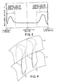
- FIG. 3 that represents an energy loss distribution in the direction of the height of the nozzle blade 10
- high energy loss areas generally distribute around the inner and the outer radial wall surfaces 13 and 14, respectively.
- the height direction range of the area hardly changes irrespective of the increase in the blade height, degradation of the efficiency owing to the secondary flow loss is reduced as the blade height increases.
- a turbine nozzle having the nozzle blade 10 curved toward an outlet side (which is hereinafter referred to as a curved nozzle) has been widely used for the purpose of reducing the secondary flow loss.
- FIG. 4 shows a configuration of a generally employed curved nozzle.
- One of reference values for defining the curved configuration is represented by a curvature range in the blade height direction.
- a curvature range in the blade height direction there are several methods for setting the curvature range including a typical method in which the curvature of a center of the blade height is set to a maximum value such that the nozzle blade is entirely curved over a whole range in the blade height direction, and a similarity expansion is made as the increase in the blade height.
- the absolute value of the curvature range changes as the blade height varies.
- the use of the curved nozzle may cause an adverse effect to deteriorate the nozzle blade performance at the center of its height, counteracting the improvement of the performance achieved by reducing the secondary loss.
- the curved configuration serves to press the fluid against the inner and outer radial wall surfaces 13 and 14 on the inner and outer rings 11 and 12 to suppress the secondary flow loss.
- the fluid flows at the reduced flow rate around the center of the nozzle blade in the height direction, which is supposed to be unaffected by the secondary loss, and accordingly exhibits the excellent performance.
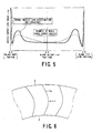
- FIG. 5 shows each of changes in the loss distribution of the curved nozzle and the normal nozzle with no curvature.
- the effect by the secondary flow may be suppressed.
- the performance of the nozzle blade may be expected to be improved over its entire height.
- the adverse effect owing to the reduced flow rate of the fluid at the center of the nozzle blade height may further be worsened. This may deteriorate the improvement of the entire performance of the curved nozzle.
- the center of the nozzle blade height has no curvature area, which is expected to provide the effect for suppressing the performance degradation caused by the reduction in the flow rate around the center of the nozzle blade height compared with the case in which the nozzle blade is curved over the entire height.
- the curvature range is defined as the proportion of the blade height. The curvature range may be increased as the blade height increases, and accordingly the performance improvement is deteriorated as the flow rate at the center of the nozzle blade height reduces.
- the loss caused by the secondary vortex generated around the wall surface in a base portion and a tip portion of the turbine nozzle has been considered as the main cause for reducing the internal efficiency of the high pressure turbine at a relatively low blade height.
- the curvature range in the blade height direction is one of reference values that indicate the configuration, and several methods have been proposed for determining such curvature range. In one of those methods, the nozzle blade is curved over its entire height so as to make a similarity expansion as the increase in the blade height.
- the fluid is pressed against the wall surface around the upper and lower wall surfaces to suppress the secondary flow loss.
- the flow rate of the fluid is reduced at the center of the blade height, thus degrading the excellent performance of the center area which has not been affected by the secondary flow, thus deteriorating improvement of the entire performance.
- the flow rate distribution at the outlet of the turbine nozzle is found disproportionately at the area especially around the wall surface of the inner and the outer rings 11 and 12 as the blade height increases. This may further worsen the adverse effect to the curved nozzle as described above.
- the curvature range is expanded. This may fail to completely eliminate the adverse effect caused by the decrease in the flow rate of the fluid at the center of the blade height.
- the curvature range is reduced. In this case, the effect for suppressing the secondary loss cannot be sufficiently obtained owing to insufficient curvature range because the area influenced by the secondary loss is ranged at a height that is almost kept constant.
- an object of the present invention is to substantially eliminate defects or drawbacks encountered in the prior art mentioned above and to provide an axial flow turbine u sing a turbine nozzle capable of suppressing the secondary flow loss caused by the secondary vortex generated around the inner and outer radial wall surfaces of the nozzle blade supported at the inner and outer rings and allowing the fluid to flow to the center of the nozzle blade height at higher rates so as to further improve the performance.
- an axial flow turbine provided with a stage composed of a turbine nozzle and a turbine rotor blade arranged in an axial flow direction, in which both end portions of a nozzle blade of the turbine nozzle are supported by a diaphragm inner ring and a diaphragm outer ring, and a flow passage is formed with its diameter expanded from an upstream stage to a downstream stage, wherein trailing edges at ends of the nozzle blade supported by the diaphragm inner ring and the diaphragm outer ring are curved to an outlet side, and an intermediate portion between the trailing edges is formed to be straight.
- an axial flow turbine comprising a casing, and a plurality of stages, provided in the casing, comprising turbine nozzles and turbine blades, respectively, wherein both ends of the nozzles of each stages are supported between a diaphragm inner ring and a diaphragm outer ring, wherein a flow passage in the stages is formed with a diameter expanded from an upstream side to a downstream side, wherein trailing edges of at least one of the nozzles are curved as a curvature to an outlet side of the flow passage around both ends thereof, and an intermediate portion between both ends of the trailing edge is formed to be straight.
- a curvature height at an end portion supported by the diaphragm outer ring of the curvature toward the outlet side is set to Ht
- a curvature height at an end portion supported by the diaphragm inner ring of the curvature toward the outlet side is set to Hr
- the curvature height at the end portion supported by the diaphragm outer ring set to Ht is in a range expressed by a relationship of 5 mm ⁇ Ht ⁇ 50 mm.
- the curvature height at the end portion supported by the diaphragm inner ring set to Hr is in a range expressed by a relationship of 5 mm ⁇ Hr ⁇ 40 mm.
- Tt a pitch between adjacent curvatures at the diaphragm outer ring support ends supported by the diaphragm outer ring
- Tr a pitch between adjacent curvatures at the diaphragm inner ring support ends supported by the diaphragm inner ring
- a center of the nozzle blade in a direction of a height is set as a position of a maximum value of a throat pitch ratio between the trailing edge of the nozzle blade and a back side of the adjacent nozzle blade.
- the nozzle blade of the above-described type may be applied to a high pressure turbine.
- the nozzle blade of the above-described type may be applied to a high pressure turbine for all stages.
- the nozzle blade of the above-described type may be applied to a nozzle blade, whose position of the trailing edge is inclined toward a direction of the axial flow from the root side to the tip side.
- the nozzle blade of the above-described type may be applied to a nozzle blade, whose position of the trailing edge is curved toward a direction of the axial flow from the root side to the tip side.
- the trailing edges at support ends of the nozzle blade supported at a diaphragm inner ring and a diaphragm outer ring are curved toward the outlet side, the intermediate portion of the trailing edge is formed straight such that the range of the curvature height at the diaphragm outer ring support end is set to be higher than that at the diaphragm inner ring support end. Since the fluid is allowed to flow to the center of the blade height at higher rates, the secondary flow loss generated at both support ends of the nozzle blade is suppressed, and more expansion work is made under the state where the flow rate of the fluid is increased for further improving the nozzle performance.
- FIG. 14 shows stages of the axial flow turbine 100 provided with nozzle blades 104.
- the nozzle blades 104 are fixed to an outer (diaphragm) ring 102 and an inner (diaphragm) ring 103, which are secured in a turbine casing 101, to form nozzle blade passages.
- a plurality of turbine movable blades 106 are disposed on the downstream side of the respective blade passages.
- the movable blades 106 are implanted on the outer periphery of a rotor disc, i.e. wheel, 105 in a row at predetermined intervals.
- a cover 107 is attached on the outer peripheral edges of the movable blades 106 in order to prevent leakage of a working fluid in the movable blades.
- the working fluid i.e. stream "S" flows from the right-hand side (upstream side) of the turbine in the figure towards the left-hand side (downstream side).
- FIG. 1 is an illustration of the turbine nozzle of the axial flow turbine according to the present invention, and with reference to FIG. 1, in the axial turbine, turbine (pressure) stages, not shown, formed by combining turbine nozzles and turbine rotor blades are arranged along a circumference of a turbine shaft.
- the turbine stages arranged along the circumference of the turbine shaft are provided toward an axial direction of the turbine shaft such that a fluid passage extends to have a diameter expanded from the upstream side to the downstream side.
- a plurality of nozzle blades 1 each having a blade height H are arranged in a row in a circumferential direction, and spaced at a pitch T between center portions of the blade heights of adjacent nozzle blades.
- the nozzle blade 1 as a curved nozzle has a trailing edge 1a of the cross section of the blade curved circumferentially toward the outlet side. It is formed to have a curvature height range in the blade height direction at the diaphragm inner ring set to Hr (mm), the curvature height range in the blade height direction at the diaphragm outer ring set to Ht (mm), and other curvature height range set to H - (Hr + Ht) which is kept straight.
- FIG. 6 is a view that represents the trailing edge 1a of the nozzle blade 1 supported at the diaphragm inner and outer rings 2 and 3 when seen from the outlet of the turbine nozzle.
- the increase in the secondary flow loss is suppressed not only around the upper and lower wall surfaces (base and tip portions) of the diaphragm inner and outer rings 2 and 3 but also at the center of the nozzle blade height.
- the range of the secondary flow loss expands as the increase in the pitch T between adjacent nozzle blades 1, 1. Assuming that the pitch between the tip portions of the adjacent nozzle blades 1, 1 is set to Tt, and the pitch between the base portions thereof is set to Tr, the relationship of Tr ⁇ Tt is established.
- the energy loss range at the tip portion of the nozzle blade 1 becomes wider than that at the base portion thereof.
- the curvature height range Hr of the base portion of the nozzle blade and the curvature height range Ht of the tip portion of the nozzle blade have a relationship of Ht ⁇ Hr.
- FIG. 8 is a graph representing a reference value indicating the nozzle performance improvement resulting from changing the curvature height range Hr of the base portion of the nozzle blade 1 independently.
- the graph shows that the reference value indicating the nozzle performance improvement is kept low unless the curvature height range M, that is 5 mm at minimum, has to be ensured and the reference value of the nozzle performance improvement is reduced even if the curvature height range is set to be equal to 40 mm or wider.
- the secondary flow loss caused by the secondary vortex is considered to have a tendency asymptotic to a predetermined lower limit value in the last result no matter how the curvature height range Hr of the base portion of the nozzle blade is increased as shown by the graph representing the reference value of the nozzle performance improvement in FIG. 9.
- the excessive curvature height range may be considered as a dominant cause that negatively works for reducing the nozzle efficiency resulting from the decrease in the flow rate at the center of the blade height.
- FIG. 10 is a graph representing a reference value indicating the nozzle performance improvement resulting from changing the curvature height range Ht of the tip portion of the nozzle blade 1 independently.
- the graph shows that the reference value indicating the nozzle performance improvement is kept low unless the curvature height range N, that is 5 mm at minimum, has to be ensured, and the reference value indicating the nozzle performance improvement is reduced even if the curvature height range is set to be equal to 50 mm or wider.
- the nozzle performance may be improved. Since the pitch between the tip portions of the nozzle blades 1 and 1 is wider than that between the base portions thereof, the resultant secondary flow range becomes wider accordingly.
- FIG. 11 is a graph representing the relationship between the nozzle energy loss and values of the nozzle blade length (nozzle height) at the initial stage, intermediate stage, and last stage of the high pressure turbines, respectively, which are changed for analytical purposes.
- the graph shows the existence of a little difference in the secondary flow loss range that changes depending on the blade length between the base portion and the tip portion of the nozzle blade 1.
- the curvature range of the nozzle blade 1 is not required to be changed even in the case of the application to the stage at the different blade height.
- the use of the aforementioned features may save the effort for searching a curvature of the nozzle blade 1 appropriate for the respective stages of the axial flow turbines among a plurality of stages each having a detailed geometrically different condition.
- the curved nozzle having the center of the blade height hardly influenced by the secondary flow may suppress degradation of the nozzle performance.
- the curvature range of the nozzle blade 1 is defined as the proportion of the blade height
- the minimum curvature range that has been determined as being required may be changed at the respective stages. Specifically, when the blade height is at the low level, the curvature range is reduced, and on the other hand, when the blade height is at the high level, the curvature range is expanded. If the aforementioned curvature range setting is applied to the nozzle blade 1 having the secondary flow influence range hardly changed in accordance with the blade height, the curvature range becomes insufficient in the case of the low level of the blade height, and the curvature range becomes excessive in the case of the high level of the blade height. There may be the case where the value that has been determined as being the best at a predetermined blade height cannot be used for other stages.
- the performance of the nozzle blade 1 with the curvature according to the embodiment may be improved even if the blade of the other configuration is combined therewith.
- the performance of the nozzle 1 may be maintained high by increasing the distribution of the flow rate at the outlet in the nozzle blade 1 where a maximum value of a nozzle throat ratio S/T, that is, the ratio of the shortest distance S between the trailing edge 1a of the nozzle blade 1 and the back side 6 of the adjacent nozzle blade 1 to the pitch T between adjacent nozzle blades 1 and 1 is set for the center of the blade height.
- a nozzle throat ratio S/T that is, the ratio of the shortest distance S between the trailing edge 1a of the nozzle blade 1 and the back side 6 of the adjacent nozzle blade 1 to the pitch T between adjacent nozzle blades 1 and 1 is set for the center of the blade height.
- the nozzle blade with the curvature according to the described embodiment is combined with the aforementioned arrangement of the blades, the reduction in the flow rate of the fluid at the center of the blade height may be compensated for further higher performance improvement in comparison with the generally employed nozzle blade as shown in FIG. 13.
- the trailing edges at both support ends of the nozzle blade supported by the diaphragm inner and outer rings are curved toward the outlet side, and the intermediate portion interposed between the trailing edges is kept straight such that the curvature height range at the diaphragm outer ring support end is higher than the one at the diaphragm inner ring support end.
- the nozzle blade having the curvature mentioned hereinabove may be applicable to conventionally existing axial flow turbines.
- the present invention may be applied to a nozzle blade, whose position of the trailing edge is inclined toward a direction of the axial flow from the root side to the tip side.
- the present invention may also be applied to a nozzle blade, whose position of the trailing edge is curved toward a direction of the axial flow from the root side to the tip side.
Landscapes
- Engineering & Computer Science (AREA)
- Mechanical Engineering (AREA)
- General Engineering & Computer Science (AREA)
- Physics & Mathematics (AREA)
- Fluid Mechanics (AREA)
- Turbine Rotor Nozzle Sealing (AREA)
Applications Claiming Priority (1)
| Application Number | Priority Date | Filing Date | Title |
|---|---|---|---|
| JP2005104056 | 2005-03-31 |
Publications (3)
| Publication Number | Publication Date |
|---|---|
| EP1710397A2 true EP1710397A2 (fr) | 2006-10-11 |
| EP1710397A3 EP1710397A3 (fr) | 2008-03-12 |
| EP1710397B1 EP1710397B1 (fr) | 2014-06-11 |
Family
ID=36579533
Family Applications (1)
| Application Number | Title | Priority Date | Filing Date |
|---|---|---|---|
| EP06006389.8A Ceased EP1710397B1 (fr) | 2005-03-31 | 2006-03-28 | Aube de guidage courbée |
Country Status (3)
| Country | Link |
|---|---|
| US (2) | US7300247B2 (fr) |
| EP (1) | EP1710397B1 (fr) |
| CN (2) | CN102588004A (fr) |
Cited By (8)
| Publication number | Priority date | Publication date | Assignee | Title |
|---|---|---|---|---|
| GB2471152A (en) * | 2009-06-17 | 2010-12-22 | Dresser Rand Co | Use of Bowed Vanes to reduce Acoustic Signature |
| EP1967694A3 (fr) * | 2007-03-08 | 2014-04-30 | Rolls-Royce plc | Aube de turbine d'une turbomachine |
| EP3656981A1 (fr) * | 2018-11-21 | 2020-05-27 | Honeywell International Inc. | Distribution de col pour rotor et pale de rotor dotée d'un carrossage et emplacement de répartition d'épaisseur maximale locale |
| US11181120B2 (en) | 2018-11-21 | 2021-11-23 | Honeywell International Inc. | Throat distribution for a rotor and rotor blade having camber and location of local maximum thickness distribution |
| US11280199B2 (en) | 2018-11-21 | 2022-03-22 | Honeywell International Inc. | Throat distribution for a rotor and rotor blade having camber and location of local maximum thickness distribution |
| US11566530B2 (en) | 2019-11-26 | 2023-01-31 | General Electric Company | Turbomachine nozzle with an airfoil having a circular trailing edge |
| US11629599B2 (en) | 2019-11-26 | 2023-04-18 | General Electric Company | Turbomachine nozzle with an airfoil having a curvilinear trailing edge |
| EP3032038B1 (fr) * | 2014-12-09 | 2024-09-04 | RTX Corporation | Vordiffusor eines gasturbinentriebwerks, gasturbinentriebwerk und verfahren zur herstellung eines vordiffusors eines gasturbinentriebwerks |
Families Citing this family (22)
| Publication number | Priority date | Publication date | Assignee | Title |
|---|---|---|---|---|
| US8524200B2 (en) | 2002-09-11 | 2013-09-03 | The Procter & Gamble Company | Tooth whitening products |
| EP1710397B1 (fr) * | 2005-03-31 | 2014-06-11 | Kabushiki Kaisha Toshiba | Aube de guidage courbée |
| EP2299239B1 (fr) * | 2008-06-30 | 2015-08-19 | Mitsubishi Hitachi Power Systems, Ltd. | Système de calcul de la courbure d'un bras d'un rotor de turbine |
| US8684684B2 (en) * | 2010-08-31 | 2014-04-01 | General Electric Company | Turbine assembly with end-wall-contoured airfoils and preferenttial clocking |
| US9109456B2 (en) | 2011-10-26 | 2015-08-18 | General Electric Company | System for coupling a segment to a rotor of a turbomachine |
| US8992179B2 (en) | 2011-10-28 | 2015-03-31 | General Electric Company | Turbine of a turbomachine |
| US9255480B2 (en) * | 2011-10-28 | 2016-02-09 | General Electric Company | Turbine of a turbomachine |
| US9051843B2 (en) | 2011-10-28 | 2015-06-09 | General Electric Company | Turbomachine blade including a squeeler pocket |
| US9803551B2 (en) * | 2011-12-20 | 2017-10-31 | Gkn Aerospace Sweden Ab | Method for manufacturing of a gas turbine engine component |
| US9404392B2 (en) | 2012-12-21 | 2016-08-02 | Elwha Llc | Heat engine system |
| US20140174085A1 (en) * | 2012-12-21 | 2014-06-26 | Elwha LLC. | Heat engine |
| US9752832B2 (en) | 2012-12-21 | 2017-09-05 | Elwha Llc | Heat pipe |
| JP5951534B2 (ja) * | 2013-03-13 | 2016-07-13 | 株式会社東芝 | 蒸気タービン |
| US9896950B2 (en) | 2013-09-09 | 2018-02-20 | Rolls-Royce Deutschland Ltd & Co Kg | Turbine guide wheel |
| US9528379B2 (en) | 2013-10-23 | 2016-12-27 | General Electric Company | Turbine bucket having serpentine core |
| US20150110617A1 (en) * | 2013-10-23 | 2015-04-23 | General Electric Company | Turbine airfoil including tip fillet |
| US9670784B2 (en) | 2013-10-23 | 2017-06-06 | General Electric Company | Turbine bucket base having serpentine cooling passage with leading edge cooling |
| US9638041B2 (en) | 2013-10-23 | 2017-05-02 | General Electric Company | Turbine bucket having non-axisymmetric base contour |
| US9551226B2 (en) | 2013-10-23 | 2017-01-24 | General Electric Company | Turbine bucket with endwall contour and airfoil profile |
| US9797258B2 (en) | 2013-10-23 | 2017-10-24 | General Electric Company | Turbine bucket including cooling passage with turn |
| US9938854B2 (en) | 2014-05-22 | 2018-04-10 | United Technologies Corporation | Gas turbine engine airfoil curvature |
| US10323528B2 (en) * | 2015-07-01 | 2019-06-18 | General Electric Company | Bulged nozzle for control of secondary flow and optimal diffuser performance |
Citations (9)
| Publication number | Priority date | Publication date | Assignee | Title |
|---|---|---|---|---|
| JPS5718405A (en) | 1980-07-07 | 1982-01-30 | Hitachi Ltd | Stage structure of turbine |
| JPS62170707A (ja) | 1986-01-24 | 1987-07-27 | Hitachi Ltd | 軸流流体機械 |
| EP0441097A1 (fr) | 1990-02-07 | 1991-08-14 | United Technologies Corporation | Profil d'aile pour la section de compression d'une machine rotative |
| EP0661413A1 (fr) | 1993-12-23 | 1995-07-05 | Mtu Motoren- Und Turbinen-Union MàNchen Gmbh | Grill d'aubes avec bord d'attaque sous la forme de flèche |
| US5474419A (en) | 1992-12-30 | 1995-12-12 | Reluzco; George | Flowpath assembly for a turbine diaphragm and methods of manufacture |
| US6036438A (en) | 1996-12-05 | 2000-03-14 | Kabushiki Kaisha Toshiba | Turbine nozzle |
| US6126394A (en) | 1996-12-27 | 2000-10-03 | Kabushiki Kaisha Toshiba | Turbine nozzle and moving blade of axial-flow turbine |
| US6491493B1 (en) | 1998-06-12 | 2002-12-10 | Ebara Corporation | Turbine nozzle vane |
| EP1422382A1 (fr) | 2001-08-31 | 2004-05-26 | Kabushiki Kaisha Toshiba | Turbine a flux axial |
Family Cites Families (8)
| Publication number | Priority date | Publication date | Assignee | Title |
|---|---|---|---|---|
| JP3132944B2 (ja) * | 1993-03-17 | 2001-02-05 | 三菱重工業株式会社 | 3次元設計タービン翼 |
| JPH0925897A (ja) * | 1995-07-11 | 1997-01-28 | Mitsubishi Heavy Ind Ltd | 軸流圧縮機の静翼 |
| JPH1061405A (ja) | 1996-08-22 | 1998-03-03 | Hitachi Ltd | 軸流形ターボ機械の静翼 |
| JP4217000B2 (ja) * | 1997-09-08 | 2009-01-28 | シーメンス アクチエンゲゼルシヤフト | 流体機械用並びに蒸気タービン用の翼 |
| US6312219B1 (en) * | 1999-11-05 | 2001-11-06 | General Electric Company | Narrow waist vane |
| US6508630B2 (en) * | 2001-03-30 | 2003-01-21 | General Electric Company | Twisted stator vane |
| JP2004263602A (ja) * | 2003-02-28 | 2004-09-24 | Toshiba Corp | 軸流タービンのノズル翼、動翼およびタービン段落 |
| EP1710397B1 (fr) * | 2005-03-31 | 2014-06-11 | Kabushiki Kaisha Toshiba | Aube de guidage courbée |
-
2006
- 2006-03-28 EP EP06006389.8A patent/EP1710397B1/fr not_active Ceased
- 2006-03-30 US US11/392,956 patent/US7300247B2/en not_active Expired - Lifetime
- 2006-03-31 CN CN2012100825541A patent/CN102588004A/zh active Pending
- 2006-03-31 CN CNA2006100710665A patent/CN1840862A/zh active Pending
-
2007
- 2007-08-22 US US11/892,375 patent/US7645119B2/en active Active
Patent Citations (9)
| Publication number | Priority date | Publication date | Assignee | Title |
|---|---|---|---|---|
| JPS5718405A (en) | 1980-07-07 | 1982-01-30 | Hitachi Ltd | Stage structure of turbine |
| JPS62170707A (ja) | 1986-01-24 | 1987-07-27 | Hitachi Ltd | 軸流流体機械 |
| EP0441097A1 (fr) | 1990-02-07 | 1991-08-14 | United Technologies Corporation | Profil d'aile pour la section de compression d'une machine rotative |
| US5474419A (en) | 1992-12-30 | 1995-12-12 | Reluzco; George | Flowpath assembly for a turbine diaphragm and methods of manufacture |
| EP0661413A1 (fr) | 1993-12-23 | 1995-07-05 | Mtu Motoren- Und Turbinen-Union MàNchen Gmbh | Grill d'aubes avec bord d'attaque sous la forme de flèche |
| US6036438A (en) | 1996-12-05 | 2000-03-14 | Kabushiki Kaisha Toshiba | Turbine nozzle |
| US6126394A (en) | 1996-12-27 | 2000-10-03 | Kabushiki Kaisha Toshiba | Turbine nozzle and moving blade of axial-flow turbine |
| US6491493B1 (en) | 1998-06-12 | 2002-12-10 | Ebara Corporation | Turbine nozzle vane |
| EP1422382A1 (fr) | 2001-08-31 | 2004-05-26 | Kabushiki Kaisha Toshiba | Turbine a flux axial |
Cited By (11)
| Publication number | Priority date | Publication date | Assignee | Title |
|---|---|---|---|---|
| EP1967694A3 (fr) * | 2007-03-08 | 2014-04-30 | Rolls-Royce plc | Aube de turbine d'une turbomachine |
| GB2471152A (en) * | 2009-06-17 | 2010-12-22 | Dresser Rand Co | Use of Bowed Vanes to reduce Acoustic Signature |
| GB2471152B (en) * | 2009-06-17 | 2016-08-10 | Dresser-Rand Company | Use of bowed nozzle vanes to reduce acoustic signature |
| EP3032038B1 (fr) * | 2014-12-09 | 2024-09-04 | RTX Corporation | Vordiffusor eines gasturbinentriebwerks, gasturbinentriebwerk und verfahren zur herstellung eines vordiffusors eines gasturbinentriebwerks |
| EP3656981A1 (fr) * | 2018-11-21 | 2020-05-27 | Honeywell International Inc. | Distribution de col pour rotor et pale de rotor dotée d'un carrossage et emplacement de répartition d'épaisseur maximale locale |
| US10859094B2 (en) | 2018-11-21 | 2020-12-08 | Honeywell International Inc. | Throat distribution for a rotor and rotor blade having camber and location of local maximum thickness distribution |
| US11181120B2 (en) | 2018-11-21 | 2021-11-23 | Honeywell International Inc. | Throat distribution for a rotor and rotor blade having camber and location of local maximum thickness distribution |
| US11280199B2 (en) | 2018-11-21 | 2022-03-22 | Honeywell International Inc. | Throat distribution for a rotor and rotor blade having camber and location of local maximum thickness distribution |
| US11378093B2 (en) | 2018-11-21 | 2022-07-05 | Honeywell International Inc. | Throat distribution for a rotor and rotor blade having camber and location of local maximum thickness distribution |
| US11566530B2 (en) | 2019-11-26 | 2023-01-31 | General Electric Company | Turbomachine nozzle with an airfoil having a circular trailing edge |
| US11629599B2 (en) | 2019-11-26 | 2023-04-18 | General Electric Company | Turbomachine nozzle with an airfoil having a curvilinear trailing edge |
Also Published As
| Publication number | Publication date |
|---|---|
| EP1710397B1 (fr) | 2014-06-11 |
| US7300247B2 (en) | 2007-11-27 |
| US20070086891A1 (en) | 2007-04-19 |
| EP1710397A3 (fr) | 2008-03-12 |
| CN102588004A (zh) | 2012-07-18 |
| CN1840862A (zh) | 2006-10-04 |
| US20080199310A1 (en) | 2008-08-21 |
| US7645119B2 (en) | 2010-01-12 |
Similar Documents
| Publication | Publication Date | Title |
|---|---|---|
| US7645119B2 (en) | Axial flow turbine | |
| US9057279B2 (en) | Labyrinth seals | |
| US7048509B2 (en) | Axial flow turbine | |
| US6837679B2 (en) | Gas turbine engine | |
| US8777558B2 (en) | Casing for a moving-blade wheel of turbomachine | |
| JP5777531B2 (ja) | 軸流ターボ機械用のエーロフォイル羽根 | |
| US9631504B2 (en) | Variable guide vane extended variable fillet | |
| US8317466B2 (en) | Blade structure of gas turbine | |
| JPH0435601B2 (fr) | ||
| RU2748318C1 (ru) | Перо лопатки компрессора | |
| CN111287801A (zh) | 蒸汽轮机叶片以及蒸汽轮机 | |
| US11492917B2 (en) | Nozzle with slash face(s) with swept surfaces joining at arc with peak aligned with stiffening member | |
| JP5426305B2 (ja) | ターボ機械 | |
| US10704393B2 (en) | Contouring of an airfoil array platform | |
| US20210254472A1 (en) | Nozzle with slash face(s) with swept surfaces with joining line aligned with stiffening member | |
| JP4869099B2 (ja) | ノズル翼および軸流タービン | |
| US10837285B2 (en) | Blade, blade ring, blade ring segment and turbomachine | |
| US20190017384A1 (en) | Turbomachine airfoil array | |
| US11566539B2 (en) | Gas turbine and gas turbine manufacturing method | |
| JP2006307846A (ja) | 軸流タービン | |
| JP2016079919A (ja) | 動翼及び軸流タービン | |
| US20230383662A1 (en) | Annulus contouring | |
| JP2008291741A (ja) | ノズル翼翼列、動翼翼列および軸流タービン |
Legal Events
| Date | Code | Title | Description |
|---|---|---|---|
| PUAI | Public reference made under article 153(3) epc to a published international application that has entered the european phase |
Free format text: ORIGINAL CODE: 0009012 |
|
| 17P | Request for examination filed |
Effective date: 20060328 |
|
| AK | Designated contracting states |
Kind code of ref document: A2 Designated state(s): AT BE BG CH CY CZ DE DK EE ES FI FR GB GR HU IE IS IT LI LT LU LV MC NL PL PT RO SE SI SK TR |
|
| AX | Request for extension of the european patent |
Extension state: AL BA HR MK YU |
|
| PUAL | Search report despatched |
Free format text: ORIGINAL CODE: 0009013 |
|
| AK | Designated contracting states |
Kind code of ref document: A3 Designated state(s): AT BE BG CH CY CZ DE DK EE ES FI FR GB GR HU IE IS IT LI LT LU LV MC NL PL PT RO SE SI SK TR |
|
| AX | Request for extension of the european patent |
Extension state: AL BA HR MK YU |
|
| 17Q | First examination report despatched |
Effective date: 20080627 |
|
| AKX | Designation fees paid |
Designated state(s): DE FR |
|
| TPAC | Observations filed by third parties |
Free format text: ORIGINAL CODE: EPIDOSNTIPA |
|
| GRAP | Despatch of communication of intention to grant a patent |
Free format text: ORIGINAL CODE: EPIDOSNIGR1 |
|
| INTG | Intention to grant announced |
Effective date: 20140109 |
|
| RIN1 | Information on inventor provided before grant (corrected) |
Inventor name: TANI, KENTARO Inventor name: ONODA, AKIHIRO Inventor name: KAWAKAMI, HIROSHI Inventor name: NOMURA, DAISUKE Inventor name: KAWASAKI, SAKAE |
|
| GRAS | Grant fee paid |
Free format text: ORIGINAL CODE: EPIDOSNIGR3 |
|
| GRAA | (expected) grant |
Free format text: ORIGINAL CODE: 0009210 |
|
| AK | Designated contracting states |
Kind code of ref document: B1 Designated state(s): DE FR |
|
| REG | Reference to a national code |
Ref country code: DE Ref legal event code: R096 Ref document number: 602006041849 Country of ref document: DE Effective date: 20140724 |
|
| REG | Reference to a national code |
Ref country code: DE Ref legal event code: R097 Ref document number: 602006041849 Country of ref document: DE |
|
| PLBE | No opposition filed within time limit |
Free format text: ORIGINAL CODE: 0009261 |
|
| STAA | Information on the status of an ep patent application or granted ep patent |
Free format text: STATUS: NO OPPOSITION FILED WITHIN TIME LIMIT |
|
| 26N | No opposition filed |
Effective date: 20150312 |
|
| REG | Reference to a national code |
Ref country code: DE Ref legal event code: R097 Ref document number: 602006041849 Country of ref document: DE Effective date: 20150312 |
|
| REG | Reference to a national code |
Ref country code: FR Ref legal event code: PLFP Year of fee payment: 11 |
|
| REG | Reference to a national code |
Ref country code: FR Ref legal event code: PLFP Year of fee payment: 12 |
|
| REG | Reference to a national code |
Ref country code: FR Ref legal event code: PLFP Year of fee payment: 13 |
|
| PGFP | Annual fee paid to national office [announced via postgrant information from national office to epo] |
Ref country code: FR Payment date: 20230208 Year of fee payment: 18 |
|
| PGFP | Annual fee paid to national office [announced via postgrant information from national office to epo] |
Ref country code: DE Payment date: 20230131 Year of fee payment: 18 |
|
| REG | Reference to a national code |
Ref country code: DE Ref legal event code: R119 Ref document number: 602006041849 Country of ref document: DE |
|
| PG25 | Lapsed in a contracting state [announced via postgrant information from national office to epo] |
Ref country code: DE Free format text: LAPSE BECAUSE OF NON-PAYMENT OF DUE FEES Effective date: 20241001 |
|
| PG25 | Lapsed in a contracting state [announced via postgrant information from national office to epo] |
Ref country code: FR Free format text: LAPSE BECAUSE OF NON-PAYMENT OF DUE FEES Effective date: 20240331 |
|
| PG25 | Lapsed in a contracting state [announced via postgrant information from national office to epo] |
Ref country code: FR Free format text: LAPSE BECAUSE OF NON-PAYMENT OF DUE FEES Effective date: 20240331 Ref country code: DE Free format text: LAPSE BECAUSE OF NON-PAYMENT OF DUE FEES Effective date: 20241001 |