EP1710445A2 - Dispositif de contrôle hydraulique - Google Patents
Dispositif de contrôle hydraulique Download PDFInfo
- Publication number
- EP1710445A2 EP1710445A2 EP05027271A EP05027271A EP1710445A2 EP 1710445 A2 EP1710445 A2 EP 1710445A2 EP 05027271 A EP05027271 A EP 05027271A EP 05027271 A EP05027271 A EP 05027271A EP 1710445 A2 EP1710445 A2 EP 1710445A2
- Authority
- EP
- European Patent Office
- Prior art keywords
- pressure
- valve
- control
- working
- load
- Prior art date
- Legal status (The legal status is an assumption and is not a legal conclusion. Google has not performed a legal analysis and makes no representation as to the accuracy of the status listed.)
- Withdrawn
Links
Images

Classifications
-
- F—MECHANICAL ENGINEERING; LIGHTING; HEATING; WEAPONS; BLASTING
- F15—FLUID-PRESSURE ACTUATORS; HYDRAULICS OR PNEUMATICS IN GENERAL
- F15B—SYSTEMS ACTING BY MEANS OF FLUIDS IN GENERAL; FLUID-PRESSURE ACTUATORS, e.g. SERVOMOTORS; DETAILS OF FLUID-PRESSURE SYSTEMS, NOT OTHERWISE PROVIDED FOR
- F15B11/00—Servomotor systems without provision for follow-up action; Circuits therefor
- F15B11/02—Systems essentially incorporating special features for controlling the speed or actuating force of an output member
- F15B11/04—Systems essentially incorporating special features for controlling the speed or actuating force of an output member for controlling the speed
- F15B11/044—Systems essentially incorporating special features for controlling the speed or actuating force of an output member for controlling the speed by means in the return line, i.e. "meter out"
- F15B11/0445—Systems essentially incorporating special features for controlling the speed or actuating force of an output member for controlling the speed by means in the return line, i.e. "meter out" with counterbalance valves, e.g. to prevent overrunning or for braking
-
- F—MECHANICAL ENGINEERING; LIGHTING; HEATING; WEAPONS; BLASTING
- F15—FLUID-PRESSURE ACTUATORS; HYDRAULICS OR PNEUMATICS IN GENERAL
- F15B—SYSTEMS ACTING BY MEANS OF FLUIDS IN GENERAL; FLUID-PRESSURE ACTUATORS, e.g. SERVOMOTORS; DETAILS OF FLUID-PRESSURE SYSTEMS, NOT OTHERWISE PROVIDED FOR
- F15B21/00—Common features of fluid actuator systems; Fluid-pressure actuator systems or details thereof, not covered by any other group of this subclass
-
- F—MECHANICAL ENGINEERING; LIGHTING; HEATING; WEAPONS; BLASTING
- F15—FLUID-PRESSURE ACTUATORS; HYDRAULICS OR PNEUMATICS IN GENERAL
- F15B—SYSTEMS ACTING BY MEANS OF FLUIDS IN GENERAL; FLUID-PRESSURE ACTUATORS, e.g. SERVOMOTORS; DETAILS OF FLUID-PRESSURE SYSTEMS, NOT OTHERWISE PROVIDED FOR
- F15B11/00—Servomotor systems without provision for follow-up action; Circuits therefor
- F15B11/02—Systems essentially incorporating special features for controlling the speed or actuating force of an output member
- F15B11/04—Systems essentially incorporating special features for controlling the speed or actuating force of an output member for controlling the speed
- F15B11/05—Systems essentially incorporating special features for controlling the speed or actuating force of an output member for controlling the speed specially adapted to maintain constant speed, e.g. pressure-compensated, load-responsive
-
- F—MECHANICAL ENGINEERING; LIGHTING; HEATING; WEAPONS; BLASTING
- F15—FLUID-PRESSURE ACTUATORS; HYDRAULICS OR PNEUMATICS IN GENERAL
- F15B—SYSTEMS ACTING BY MEANS OF FLUIDS IN GENERAL; FLUID-PRESSURE ACTUATORS, e.g. SERVOMOTORS; DETAILS OF FLUID-PRESSURE SYSTEMS, NOT OTHERWISE PROVIDED FOR
- F15B2211/00—Circuits for servomotor systems
- F15B2211/20—Fluid pressure source, e.g. accumulator or variable axial piston pump
- F15B2211/205—Systems with pumps
- F15B2211/2053—Type of pump
- F15B2211/20546—Type of pump variable capacity
- F15B2211/20553—Type of pump variable capacity with pilot circuit, e.g. for controlling a swash plate
-
- F—MECHANICAL ENGINEERING; LIGHTING; HEATING; WEAPONS; BLASTING
- F15—FLUID-PRESSURE ACTUATORS; HYDRAULICS OR PNEUMATICS IN GENERAL
- F15B—SYSTEMS ACTING BY MEANS OF FLUIDS IN GENERAL; FLUID-PRESSURE ACTUATORS, e.g. SERVOMOTORS; DETAILS OF FLUID-PRESSURE SYSTEMS, NOT OTHERWISE PROVIDED FOR
- F15B2211/00—Circuits for servomotor systems
- F15B2211/30—Directional control
- F15B2211/305—Directional control characterised by the type of valves
- F15B2211/30525—Directional control valves, e.g. 4/3-directional control valve
-
- F—MECHANICAL ENGINEERING; LIGHTING; HEATING; WEAPONS; BLASTING
- F15—FLUID-PRESSURE ACTUATORS; HYDRAULICS OR PNEUMATICS IN GENERAL
- F15B—SYSTEMS ACTING BY MEANS OF FLUIDS IN GENERAL; FLUID-PRESSURE ACTUATORS, e.g. SERVOMOTORS; DETAILS OF FLUID-PRESSURE SYSTEMS, NOT OTHERWISE PROVIDED FOR
- F15B2211/00—Circuits for servomotor systems
- F15B2211/30—Directional control
- F15B2211/305—Directional control characterised by the type of valves
- F15B2211/30525—Directional control valves, e.g. 4/3-directional control valve
- F15B2211/3053—In combination with a pressure compensating valve
- F15B2211/30535—In combination with a pressure compensating valve the pressure compensating valve is arranged between pressure source and directional control valve
-
- F—MECHANICAL ENGINEERING; LIGHTING; HEATING; WEAPONS; BLASTING
- F15—FLUID-PRESSURE ACTUATORS; HYDRAULICS OR PNEUMATICS IN GENERAL
- F15B—SYSTEMS ACTING BY MEANS OF FLUIDS IN GENERAL; FLUID-PRESSURE ACTUATORS, e.g. SERVOMOTORS; DETAILS OF FLUID-PRESSURE SYSTEMS, NOT OTHERWISE PROVIDED FOR
- F15B2211/00—Circuits for servomotor systems
- F15B2211/30—Directional control
- F15B2211/31—Directional control characterised by the positions of the valve element
- F15B2211/3122—Special positions other than the pump port being connected to working ports or the working ports being connected to the return line
- F15B2211/3127—Floating position connecting the working ports and the return line
-
- F—MECHANICAL ENGINEERING; LIGHTING; HEATING; WEAPONS; BLASTING
- F15—FLUID-PRESSURE ACTUATORS; HYDRAULICS OR PNEUMATICS IN GENERAL
- F15B—SYSTEMS ACTING BY MEANS OF FLUIDS IN GENERAL; FLUID-PRESSURE ACTUATORS, e.g. SERVOMOTORS; DETAILS OF FLUID-PRESSURE SYSTEMS, NOT OTHERWISE PROVIDED FOR
- F15B2211/00—Circuits for servomotor systems
- F15B2211/30—Directional control
- F15B2211/32—Directional control characterised by the type of actuation
- F15B2211/329—Directional control characterised by the type of actuation actuated by fluid pressure
-
- F—MECHANICAL ENGINEERING; LIGHTING; HEATING; WEAPONS; BLASTING
- F15—FLUID-PRESSURE ACTUATORS; HYDRAULICS OR PNEUMATICS IN GENERAL
- F15B—SYSTEMS ACTING BY MEANS OF FLUIDS IN GENERAL; FLUID-PRESSURE ACTUATORS, e.g. SERVOMOTORS; DETAILS OF FLUID-PRESSURE SYSTEMS, NOT OTHERWISE PROVIDED FOR
- F15B2211/00—Circuits for servomotor systems
- F15B2211/40—Flow control
- F15B2211/405—Flow control characterised by the type of flow control means or valve
- F15B2211/40515—Flow control characterised by the type of flow control means or valve with variable throttles or orifices
-
- F—MECHANICAL ENGINEERING; LIGHTING; HEATING; WEAPONS; BLASTING
- F15—FLUID-PRESSURE ACTUATORS; HYDRAULICS OR PNEUMATICS IN GENERAL
- F15B—SYSTEMS ACTING BY MEANS OF FLUIDS IN GENERAL; FLUID-PRESSURE ACTUATORS, e.g. SERVOMOTORS; DETAILS OF FLUID-PRESSURE SYSTEMS, NOT OTHERWISE PROVIDED FOR
- F15B2211/00—Circuits for servomotor systems
- F15B2211/40—Flow control
- F15B2211/42—Flow control characterised by the type of actuation
- F15B2211/421—Flow control characterised by the type of actuation mechanically
-
- F—MECHANICAL ENGINEERING; LIGHTING; HEATING; WEAPONS; BLASTING
- F15—FLUID-PRESSURE ACTUATORS; HYDRAULICS OR PNEUMATICS IN GENERAL
- F15B—SYSTEMS ACTING BY MEANS OF FLUIDS IN GENERAL; FLUID-PRESSURE ACTUATORS, e.g. SERVOMOTORS; DETAILS OF FLUID-PRESSURE SYSTEMS, NOT OTHERWISE PROVIDED FOR
- F15B2211/00—Circuits for servomotor systems
- F15B2211/40—Flow control
- F15B2211/42—Flow control characterised by the type of actuation
- F15B2211/428—Flow control characterised by the type of actuation actuated by fluid pressure
-
- F—MECHANICAL ENGINEERING; LIGHTING; HEATING; WEAPONS; BLASTING
- F15—FLUID-PRESSURE ACTUATORS; HYDRAULICS OR PNEUMATICS IN GENERAL
- F15B—SYSTEMS ACTING BY MEANS OF FLUIDS IN GENERAL; FLUID-PRESSURE ACTUATORS, e.g. SERVOMOTORS; DETAILS OF FLUID-PRESSURE SYSTEMS, NOT OTHERWISE PROVIDED FOR
- F15B2211/00—Circuits for servomotor systems
- F15B2211/40—Flow control
- F15B2211/45—Control of bleed-off flow, e.g. control of bypass flow to the return line
-
- F—MECHANICAL ENGINEERING; LIGHTING; HEATING; WEAPONS; BLASTING
- F15—FLUID-PRESSURE ACTUATORS; HYDRAULICS OR PNEUMATICS IN GENERAL
- F15B—SYSTEMS ACTING BY MEANS OF FLUIDS IN GENERAL; FLUID-PRESSURE ACTUATORS, e.g. SERVOMOTORS; DETAILS OF FLUID-PRESSURE SYSTEMS, NOT OTHERWISE PROVIDED FOR
- F15B2211/00—Circuits for servomotor systems
- F15B2211/40—Flow control
- F15B2211/455—Control of flow in the feed line, i.e. meter-in control
-
- F—MECHANICAL ENGINEERING; LIGHTING; HEATING; WEAPONS; BLASTING
- F15—FLUID-PRESSURE ACTUATORS; HYDRAULICS OR PNEUMATICS IN GENERAL
- F15B—SYSTEMS ACTING BY MEANS OF FLUIDS IN GENERAL; FLUID-PRESSURE ACTUATORS, e.g. SERVOMOTORS; DETAILS OF FLUID-PRESSURE SYSTEMS, NOT OTHERWISE PROVIDED FOR
- F15B2211/00—Circuits for servomotor systems
- F15B2211/40—Flow control
- F15B2211/46—Control of flow in the return line, i.e. meter-out control
-
- F—MECHANICAL ENGINEERING; LIGHTING; HEATING; WEAPONS; BLASTING
- F15—FLUID-PRESSURE ACTUATORS; HYDRAULICS OR PNEUMATICS IN GENERAL
- F15B—SYSTEMS ACTING BY MEANS OF FLUIDS IN GENERAL; FLUID-PRESSURE ACTUATORS, e.g. SERVOMOTORS; DETAILS OF FLUID-PRESSURE SYSTEMS, NOT OTHERWISE PROVIDED FOR
- F15B2211/00—Circuits for servomotor systems
- F15B2211/40—Flow control
- F15B2211/47—Flow control in one direction only
- F15B2211/473—Flow control in one direction only without restriction in the reverse direction
-
- F—MECHANICAL ENGINEERING; LIGHTING; HEATING; WEAPONS; BLASTING
- F15—FLUID-PRESSURE ACTUATORS; HYDRAULICS OR PNEUMATICS IN GENERAL
- F15B—SYSTEMS ACTING BY MEANS OF FLUIDS IN GENERAL; FLUID-PRESSURE ACTUATORS, e.g. SERVOMOTORS; DETAILS OF FLUID-PRESSURE SYSTEMS, NOT OTHERWISE PROVIDED FOR
- F15B2211/00—Circuits for servomotor systems
- F15B2211/50—Pressure control
- F15B2211/505—Pressure control characterised by the type of pressure control means
- F15B2211/50509—Pressure control characterised by the type of pressure control means the pressure control means controlling a pressure upstream of the pressure control means
- F15B2211/50518—Pressure control characterised by the type of pressure control means the pressure control means controlling a pressure upstream of the pressure control means using pressure relief valves
-
- F—MECHANICAL ENGINEERING; LIGHTING; HEATING; WEAPONS; BLASTING
- F15—FLUID-PRESSURE ACTUATORS; HYDRAULICS OR PNEUMATICS IN GENERAL
- F15B—SYSTEMS ACTING BY MEANS OF FLUIDS IN GENERAL; FLUID-PRESSURE ACTUATORS, e.g. SERVOMOTORS; DETAILS OF FLUID-PRESSURE SYSTEMS, NOT OTHERWISE PROVIDED FOR
- F15B2211/00—Circuits for servomotor systems
- F15B2211/50—Pressure control
- F15B2211/505—Pressure control characterised by the type of pressure control means
- F15B2211/50509—Pressure control characterised by the type of pressure control means the pressure control means controlling a pressure upstream of the pressure control means
- F15B2211/50545—Pressure control characterised by the type of pressure control means the pressure control means controlling a pressure upstream of the pressure control means using braking valves to maintain a back pressure
-
- F—MECHANICAL ENGINEERING; LIGHTING; HEATING; WEAPONS; BLASTING
- F15—FLUID-PRESSURE ACTUATORS; HYDRAULICS OR PNEUMATICS IN GENERAL
- F15B—SYSTEMS ACTING BY MEANS OF FLUIDS IN GENERAL; FLUID-PRESSURE ACTUATORS, e.g. SERVOMOTORS; DETAILS OF FLUID-PRESSURE SYSTEMS, NOT OTHERWISE PROVIDED FOR
- F15B2211/00—Circuits for servomotor systems
- F15B2211/50—Pressure control
- F15B2211/505—Pressure control characterised by the type of pressure control means
- F15B2211/50563—Pressure control characterised by the type of pressure control means the pressure control means controlling a differential pressure
-
- F—MECHANICAL ENGINEERING; LIGHTING; HEATING; WEAPONS; BLASTING
- F15—FLUID-PRESSURE ACTUATORS; HYDRAULICS OR PNEUMATICS IN GENERAL
- F15B—SYSTEMS ACTING BY MEANS OF FLUIDS IN GENERAL; FLUID-PRESSURE ACTUATORS, e.g. SERVOMOTORS; DETAILS OF FLUID-PRESSURE SYSTEMS, NOT OTHERWISE PROVIDED FOR
- F15B2211/00—Circuits for servomotor systems
- F15B2211/50—Pressure control
- F15B2211/505—Pressure control characterised by the type of pressure control means
- F15B2211/50563—Pressure control characterised by the type of pressure control means the pressure control means controlling a differential pressure
- F15B2211/50572—Pressure control characterised by the type of pressure control means the pressure control means controlling a differential pressure using a pressure compensating valve for controlling the pressure difference across a flow control valve
-
- F—MECHANICAL ENGINEERING; LIGHTING; HEATING; WEAPONS; BLASTING
- F15—FLUID-PRESSURE ACTUATORS; HYDRAULICS OR PNEUMATICS IN GENERAL
- F15B—SYSTEMS ACTING BY MEANS OF FLUIDS IN GENERAL; FLUID-PRESSURE ACTUATORS, e.g. SERVOMOTORS; DETAILS OF FLUID-PRESSURE SYSTEMS, NOT OTHERWISE PROVIDED FOR
- F15B2211/00—Circuits for servomotor systems
- F15B2211/50—Pressure control
- F15B2211/505—Pressure control characterised by the type of pressure control means
- F15B2211/50563—Pressure control characterised by the type of pressure control means the pressure control means controlling a differential pressure
- F15B2211/50581—Pressure control characterised by the type of pressure control means the pressure control means controlling a differential pressure using counterbalance valves
-
- F—MECHANICAL ENGINEERING; LIGHTING; HEATING; WEAPONS; BLASTING
- F15—FLUID-PRESSURE ACTUATORS; HYDRAULICS OR PNEUMATICS IN GENERAL
- F15B—SYSTEMS ACTING BY MEANS OF FLUIDS IN GENERAL; FLUID-PRESSURE ACTUATORS, e.g. SERVOMOTORS; DETAILS OF FLUID-PRESSURE SYSTEMS, NOT OTHERWISE PROVIDED FOR
- F15B2211/00—Circuits for servomotor systems
- F15B2211/50—Pressure control
- F15B2211/515—Pressure control characterised by the connections of the pressure control means in the circuit
- F15B2211/5153—Pressure control characterised by the connections of the pressure control means in the circuit being connected to an output member and a directional control valve
-
- F—MECHANICAL ENGINEERING; LIGHTING; HEATING; WEAPONS; BLASTING
- F15—FLUID-PRESSURE ACTUATORS; HYDRAULICS OR PNEUMATICS IN GENERAL
- F15B—SYSTEMS ACTING BY MEANS OF FLUIDS IN GENERAL; FLUID-PRESSURE ACTUATORS, e.g. SERVOMOTORS; DETAILS OF FLUID-PRESSURE SYSTEMS, NOT OTHERWISE PROVIDED FOR
- F15B2211/00—Circuits for servomotor systems
- F15B2211/50—Pressure control
- F15B2211/55—Pressure control for limiting a pressure up to a maximum pressure, e.g. by using a pressure relief valve
-
- F—MECHANICAL ENGINEERING; LIGHTING; HEATING; WEAPONS; BLASTING
- F15—FLUID-PRESSURE ACTUATORS; HYDRAULICS OR PNEUMATICS IN GENERAL
- F15B—SYSTEMS ACTING BY MEANS OF FLUIDS IN GENERAL; FLUID-PRESSURE ACTUATORS, e.g. SERVOMOTORS; DETAILS OF FLUID-PRESSURE SYSTEMS, NOT OTHERWISE PROVIDED FOR
- F15B2211/00—Circuits for servomotor systems
- F15B2211/50—Pressure control
- F15B2211/575—Pilot pressure control
-
- F—MECHANICAL ENGINEERING; LIGHTING; HEATING; WEAPONS; BLASTING
- F15—FLUID-PRESSURE ACTUATORS; HYDRAULICS OR PNEUMATICS IN GENERAL
- F15B—SYSTEMS ACTING BY MEANS OF FLUIDS IN GENERAL; FLUID-PRESSURE ACTUATORS, e.g. SERVOMOTORS; DETAILS OF FLUID-PRESSURE SYSTEMS, NOT OTHERWISE PROVIDED FOR
- F15B2211/00—Circuits for servomotor systems
- F15B2211/60—Circuit components or control therefor
- F15B2211/605—Load sensing circuits
- F15B2211/6051—Load sensing circuits having valve means between output member and the load sensing circuit
- F15B2211/6052—Load sensing circuits having valve means between output member and the load sensing circuit using check valves
-
- F—MECHANICAL ENGINEERING; LIGHTING; HEATING; WEAPONS; BLASTING
- F15—FLUID-PRESSURE ACTUATORS; HYDRAULICS OR PNEUMATICS IN GENERAL
- F15B—SYSTEMS ACTING BY MEANS OF FLUIDS IN GENERAL; FLUID-PRESSURE ACTUATORS, e.g. SERVOMOTORS; DETAILS OF FLUID-PRESSURE SYSTEMS, NOT OTHERWISE PROVIDED FOR
- F15B2211/00—Circuits for servomotor systems
- F15B2211/60—Circuit components or control therefor
- F15B2211/605—Load sensing circuits
- F15B2211/6051—Load sensing circuits having valve means between output member and the load sensing circuit
- F15B2211/6054—Load sensing circuits having valve means between output member and the load sensing circuit using shuttle valves
-
- F—MECHANICAL ENGINEERING; LIGHTING; HEATING; WEAPONS; BLASTING
- F15—FLUID-PRESSURE ACTUATORS; HYDRAULICS OR PNEUMATICS IN GENERAL
- F15B—SYSTEMS ACTING BY MEANS OF FLUIDS IN GENERAL; FLUID-PRESSURE ACTUATORS, e.g. SERVOMOTORS; DETAILS OF FLUID-PRESSURE SYSTEMS, NOT OTHERWISE PROVIDED FOR
- F15B2211/00—Circuits for servomotor systems
- F15B2211/60—Circuit components or control therefor
- F15B2211/605—Load sensing circuits
- F15B2211/6051—Load sensing circuits having valve means between output member and the load sensing circuit
- F15B2211/6055—Load sensing circuits having valve means between output member and the load sensing circuit using pressure relief valves
-
- F—MECHANICAL ENGINEERING; LIGHTING; HEATING; WEAPONS; BLASTING
- F15—FLUID-PRESSURE ACTUATORS; HYDRAULICS OR PNEUMATICS IN GENERAL
- F15B—SYSTEMS ACTING BY MEANS OF FLUIDS IN GENERAL; FLUID-PRESSURE ACTUATORS, e.g. SERVOMOTORS; DETAILS OF FLUID-PRESSURE SYSTEMS, NOT OTHERWISE PROVIDED FOR
- F15B2211/00—Circuits for servomotor systems
- F15B2211/70—Output members, e.g. hydraulic motors or cylinders or control therefor
- F15B2211/705—Output members, e.g. hydraulic motors or cylinders or control therefor characterised by the type of output members or actuators
- F15B2211/7051—Linear output members
- F15B2211/7053—Double-acting output members
-
- F—MECHANICAL ENGINEERING; LIGHTING; HEATING; WEAPONS; BLASTING
- F15—FLUID-PRESSURE ACTUATORS; HYDRAULICS OR PNEUMATICS IN GENERAL
- F15B—SYSTEMS ACTING BY MEANS OF FLUIDS IN GENERAL; FLUID-PRESSURE ACTUATORS, e.g. SERVOMOTORS; DETAILS OF FLUID-PRESSURE SYSTEMS, NOT OTHERWISE PROVIDED FOR
- F15B2211/00—Circuits for servomotor systems
- F15B2211/70—Output members, e.g. hydraulic motors or cylinders or control therefor
- F15B2211/705—Output members, e.g. hydraulic motors or cylinders or control therefor characterised by the type of output members or actuators
- F15B2211/7058—Rotary output members
-
- F—MECHANICAL ENGINEERING; LIGHTING; HEATING; WEAPONS; BLASTING
- F15—FLUID-PRESSURE ACTUATORS; HYDRAULICS OR PNEUMATICS IN GENERAL
- F15B—SYSTEMS ACTING BY MEANS OF FLUIDS IN GENERAL; FLUID-PRESSURE ACTUATORS, e.g. SERVOMOTORS; DETAILS OF FLUID-PRESSURE SYSTEMS, NOT OTHERWISE PROVIDED FOR
- F15B2211/00—Circuits for servomotor systems
- F15B2211/70—Output members, e.g. hydraulic motors or cylinders or control therefor
- F15B2211/76—Control of force or torque of the output member
-
- F—MECHANICAL ENGINEERING; LIGHTING; HEATING; WEAPONS; BLASTING
- F15—FLUID-PRESSURE ACTUATORS; HYDRAULICS OR PNEUMATICS IN GENERAL
- F15B—SYSTEMS ACTING BY MEANS OF FLUIDS IN GENERAL; FLUID-PRESSURE ACTUATORS, e.g. SERVOMOTORS; DETAILS OF FLUID-PRESSURE SYSTEMS, NOT OTHERWISE PROVIDED FOR
- F15B2211/00—Circuits for servomotor systems
- F15B2211/70—Output members, e.g. hydraulic motors or cylinders or control therefor
- F15B2211/76—Control of force or torque of the output member
- F15B2211/761—Control of a negative load, i.e. of a load generating hydraulic energy
Definitions
- the invention relates to a hydraulic control with a supply connection arrangement having a high-pressure connection and a low-pressure connection, a working connection arrangement having two connectable with a consumer working ports, a control valve with a valve element between the supply port arrangement and the working port arrangement and a compensation valve which between the high pressure port and the control valve is arranged and which is acted upon in the closing direction by a pressure between the compensation valve and the control valve. Furthermore, the invention relates to a method for controlling a hydraulic consumer, which is controlled by a control valve in a pressure control mode.
- the Compensation valve is in the opening direction with an opening spring and acted upon by a pressure that can be removed via a fixed throttle.
- the fixed throttle is part of a pressure divider between the output of the compensation valve and the low-pressure connection, which is designed here as a tank connection.
- the compensation valve thus provides for a pressure control in which the engine inflow pressure has a value substantially determined by the position of the control valve.
- a compensation valve and a load-holding valve is arranged in series.
- the load-holding valve is fed via a pilot line of Motorzufluß réelle in the opening direction and a further pilot line, the pressure at the output of the load-holding valve.
- the load-holding valve is therefore under the influence of a spring so that it opens only when the pressure difference has overcome the spring force.
- the invention has for its object to make energy consumption as low as possible.
- This object is achieved in a hydraulic control of the type mentioned above in that the compensation valve in the opening direction of a pressure of a selector can be acted upon, which selectively supplies the compensation valve, a pressure control pressure or a flow control pressure.
- the selector supply the higher pressure of pressure control pressure and flow control pressure to the compensation valve. This has two advantages. On the one hand, it is easier to decide which of the two pressures should be selected. On the other hand, the operation of the selection device can be automated in this way.
- the selector upon actuation of the control valve from a predetermined position, the selector initially communicates the pressure control pressure and then the flow control pressure to the compensating valve.
- This position can be, for example, a "zero position” or “neutral position", which is used by way of example for explanation.
- this predetermined position may also lie elsewhere.
- the control valve When the control valve is moved out of its zero position, it opens increasingly and thus passes hydraulic fluid from the high pressure port, which is usually designed as a pump port, to a working port on.
- the control In the initial phase of this control section, the control is then operated in a pressure control mode in which the pressure at the outlet of the control valve depends substantially on the position of the valve member of the control valve.
- valve element for example a valve spool.
- This pressure can then be used, for example, to open other valves in the controller, such as a load-holding valve.
- This load-holding valve must then be designed only for this relatively low pressure, which is made possible by the pressure control.
- the control valve which is preferably designed as a proportional valve, then supplies the corresponding amount of hydraulic fluid, so in simple terms controls the speed at which the consumer is operated.
- the energetically most favorable pressure is automatically set in a pressure range which is bounded below by the minimum pressure predetermined by the pressure control and optionally by an overpressure valve, ie the pressure required by the consumer.
- the external conditions decide which form of control is active. Of course, this also applies in the "initial phase".
- the selection device is connected on the one hand to a working line which is arranged between the control valve and a working connection, and on the other hand to a control line connected to a load-sensing line.
- a working line which is arranged between the control valve and a working connection
- a control line connected to a load-sensing line.
- control line is connected to a tap of a pressure divider which is arranged between the compensation valve and the low-pressure connection.
- the same pressure divider can also be used to generate the load sensing signal.
- a further choke is arranged in order to effect a certain decoupling.
- a pressure is removed, which acts on the compensation valve in the opening direction. This is a relatively simple construction to effect pressure control.
- the pressure divider on at least two throttles, one of which is adjustable by the valve element of the control valve.
- This throttle is usually the throttle between the tap and the low pressure port.
- the pressure divider on two throttles, both with the Valve element of the control valve are adjustable. If the throttles of the pressure divider have a constant value, then the pressure at the outlet of the control valve in the pressure control region remains substantially constant. If these chokes have a variable value, then you can raise or lower the pressure.
- the selection device has a check valve which opens in the direction of the compensation valve. This is a relatively simple embodiment, but sufficient if you want to forward only the higher of the two pressures to the compensation valve.
- the check valve is arranged in the valve element of the control valve. In this case, you have to make only minor changes to the controller itself. Only a small change in the valve element of the control valve is required.
- the selection device may have a shuttle valve.
- a shuttle valve is, so to speak, a check valve with two check valve functions.
- such a shuttle valve may be arranged in the valve element of the control valve.
- a load-holding valve is arranged on at least one working port, which can be opened by a pilot control device from the pressure at the other working port.
- a load-holding valve is also referred to as "overcenter" valve.
- a predetermined opening pressure is required for such a load-holding valve. This opening pressure can not be too be made small, so that the load-holding valve does not accidentally open when due to leakage or other adverse circumstances results in a pressure build-up, which leads to the opening of the load-holding valve.
- With a pilot control device can now hold the opening pressure of the load-holding valve relatively high, while maintaining the necessary safety distance to parasitically constructive pressures without having to drive the energy cost to open the load-holding valve too high.
- a pressure at the other working port to open the load-holding valve, which is sufficient to actuate the pilot control device.
- a pressure may for example correspond to the minimum pressure which is predetermined by the pressure control. To lower a load you do not have to build up more pressure than absolutely necessary.
- this pressure may correspond to the pressure of the opening spring on the compensation valve plus the pressure at the tap of the pressure divider in front of the control valve.
- a return compensation valve between the consumer or the working port and the control valve can be used.
- the pilot control device has a controllable from the pressure at the other working port pilot valve element which establishes a connection from the one working port to a control input of the load-holding valve in the controlled state and interrupts in the non-activated state. This is a relatively simple embodiment of a pilot control device.
- the working connection arrangement is connected to a Nachsaug Rhein having a refill valve with a Vietnamese spallventilelement which is displaced by a pressure at a working port and establishes a connection between a consumer terminal and the other working port.
- the connection can be made so that the consumer practically no restrictions by throttling, bottlenecks in a valve block or the like are present. Accordingly, refilling can be carried out at a lower pressure than heretofore, so that in a sliding operation, that is to say when operating with negative loads, one also manages with relatively little additional energy.
- the output of the selection device is connected to a pressure relief valve.
- the pressure relief valve which is adjusted depending on the application, then, for example, the pressure control pressure with the change in the position of the valve element of the control valve can raise or lower.
- the object is achieved in a method of the type mentioned above in that the consumer is controlled by the control valve alternatively in a flow control mode and the switching between pressure control and flow control mode automatically takes place in dependence on the prevailing Drükken.
- the pressure is determined by the consumer.
- the pressure control mode the pressure from the control valve is determined. The transition between these two modes of operation then depends on the pressures at the consumer connection. For example, one can use the above-mentioned selection device for this purpose. But you can also implement such a procedure in other ways, for example, with electrically driven components.
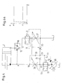
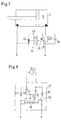
- Fig. 1 shows a hydraulic control 1, which serves to control a consumer 2, which is designed here as a piston-cylinder arrangement with a piston 3 and a cylinder 4.
- the piston 3 divides the cylinder into a first pressure chamber 5 and a second pressure chamber 6.
- the two pressure chambers 5, 6 are connected to working ports A, B of the controller 1.
- the two working connections A, B together form a working connection arrangement.
- the controller 1 has a supply connection arrangement 7, which has a high-pressure connection P, which is designed as a pump connection, a low-pressure connection T, which is designed as a tank connection, and a load-sensing connection LS.
- a control valve 8 is arranged, which has a valve slide 9 as a valve element.
- the valve spool 9 is displaceable in a total of five different operating states by means of a drive 10, which is shown only schematically, which may be designed, for example, as an electromagnetic drive or as a pilot-controlled drive. These operating states are represented by five positions ae.
- the valve spool 9 in the control valve 8 but is practically continuously movable, so that he can basically take any intermediate position.
- the control valve 8 is designed here as a proportional valve.
- valve slide 9 grooves and other recesses on its circumference, possibly bores and the like, which come into coincidence with corresponding annular grooves, recesses and holes in a housing of the control valve 8 and thereby in dependence From the position of the valve spool 9 certain connections between the supply terminal assembly 7 and the working port arrangement A, B release more or less throttled or lock.
- Examples which show the housing of such a control valve and an associated slide are known, for example, from US Pat. No. 4,981,159 mentioned in the introduction. Depending on the needs of the skilled person will be able to form such a slider and a corresponding housing.
- a compensation valve 11 is arranged between the control valve 8 and the high-pressure port P.
- the compensation valve 11 is loaded in the opening direction by the force of a spring 12 and the pressure in a control line 14.
- the compensation valve 11 is connected via a line 13 with its output, that is, a point between the compensation valve 11 and the control valve 8. In the closing direction so the input pressure of the control valve 8 acts on the compensation valve eleventh
- the working port A referred to as "lifting port”, because hydraulic fluid is fed through it in the larger pressure chamber 5, which leads to raising or extending the piston 3.
- the working connection B is referred to as a "lowering connection”.
- hydraulic fluid must be fed under pressure to lower the piston 3 again or retract.
- a load-holding valve 15 is connected, which can be controlled by the pressure at the lowering connection B.
- the load-holding valve 15 is bridged by a check valve 16 which opens toward the first pressure chamber 5.
- the lifting connection A is connected via a return compensation valve 17 to a first working outlet 18 of the control valve 8.
- the control valve 8 has a second working outlet 19, which is connected to the lowering connection B. If negative loads occur, the lifting port A is controlled by the return compensation valve 17, as is known for example from DE 102 16 958 B3.
- control valve 8 has a first load-sensing output 20 and a second load-sensing output 21.
- the first working outlet 18, the second working outlet 19, the first load-sensing outlet 20 and the second load-sensing outlet 21 are connected to the low-pressure connection T.
- the consumer 2 is thus, so to speak, in a "floating position".
- valve slide 9 In a lifting position e, the valve slide 9 is moved so that the first working outlet 18 and the first load-sensing outlet 20 is connected to the pressure input 22.
- the second pressure outlet 19 and the second load sensing port 21 are connected to the low pressure port T. Hydraulic fluid under pressure is then conveyed to the lifting port A and passes through the check valve 16 into the pressure chamber 5.
- the piston 3 moves to the right. This is a normal mode of operation.
- the second load-sensing output 21 is connected to a tap 23 of a pressure divider, which is formed by two throttles 24, 25.
- the throttle 25 is in this case arranged between the tap 23 and the low-pressure connection T.
- the throttle 24 is disposed between the tap 23 and the pressure input 22.
- the throttle 24 can be formed as a constant throttle, that is independent of the position of the valve slide flow resistance, while the flow resistance of the throttle 25 by adjusting the valve spool 9 is variable.
- the second load-sensing output 21 is connected via an aperture 26 and a shuttle valve 27 to the control line 14 in connection. Furthermore, the second load-sensing output 21 is connected to the load-sensing connection LS of the supply connection arrangement 7 via a second change-over valve 28 connected downstream of the change-over valve 27.
- the first shuttle valve 27 is connected via an aperture 26a to the first load-sensing output 20.
- the second load-sensing output 21 is connected to an input of a selection device 29. With this selection device and the second working output 19 is connected.
- the selector 29 has a check valve 30 in the line connected to the second working port 19, so that at the output 31 of the selector 29 always the greater of the two pressures at the second working port 19 and the second load sensing output 21 is present.
- the pressure at the second load-sensing output 21 is greater than the pressure at the second working output 19. This is because the valve spool 9 generates a relatively large throttle effect at the beginning of its movement with the control valve 8. In this case, the pressure at the second working port 19 is changed in proportion to the movement of the valve spool 9. This is a section P1 in FIG. In this area, the controller 1 operates as a pressure control.
- a hybrid pressure H that is, a pressure composed partly of the pressure control and partly of the flow control.
- the "FC control" area indicates that only the flow is controlled here. The pressure is automatically set. If the external conditions are different, other sequences of pressure and flow control may result.
- the lowering connection B is also assigned a pilot-controlled shut-off valve 34.
- a variable displacement pump 35 which is controlled via the load-sensing connection LS.
- the control valve 8 is symbolized here only by two “large” throttles 36, 37 and the “small” throttle 25 and the throttle 24.
- the large throttles 36, 37 and the small throttle 25 are adjustable in dependence on the position of the valve spool 9 in the control valve 8.
- the compensation valve 11 is thus controlled by the pressure difference between the pressure input 22 and the tap 23.
- the pressure at the second working port 19 is then proportional to the displacement of the valve spool 9.
- the pressure is such that, at least when it has reached its maximum value, it is sufficient to open the load-holding valve 15. A higher pressure is not required to open the load-holding valve 15. In this area, the valve spool is moved by about 1 to 2 mm.
- the check valve 30, i. the selector 29 changes from the pressure control to the flow control.
- the flow to the consumer 2 is determined by the position of the valve spool 9.
- the pressure is determined by the consumer. In this area, the valve spool is moved by a further 3 to 4 mm.
- FIG. 4a A corresponding operating diagram is shown in FIG. 4a.
- a maximum pressure H2 is limited by the pressure relief valve 32. Between H1 and H2, the pressure is determined by the consumer 2.
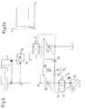
- Fig. 5 shows a modified embodiment.
- the same elements are provided with the same reference numerals.
- the check valve 30 is now replaced by a shuttle valve 38, whose one input to the second working port 19 and whose other input is connected to the tap 23. This results, as can be seen from Fig. 5a, practically the same performance.
- the shuttle valve 38 forwards the higher of the two pressures from the second working outlet 19 and tap 23 to the compensation valve 11.
- shuttle valve 38 may optionally be integrated into the valve spool 9.
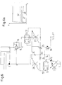
- Fig. 6 an embodiment is shown schematically, which substantially corresponds to the embodiment of FIG. 4.
- the control line 14 is not only connected to the tap 23, but in addition to a relief valve 39, which opens to the tank T.
- the discharge is set depending on the consumer 2.
- a minimum pressure curve 40 which can be shifted between two limits 41, 42, results in the flow control range.
- the pressure at flow control by the consumer 2 is determined. If the pressure provided by the pressure control is too low to move the load, for example a load, then takes over the flow control.
- the controller is adapted to operate a motor for lifting a load. Accordingly, it is sufficient if the selector 29 has a check valve 30 only for the lowering connection B.
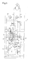
- Fig. 3 shows a controller 1, which is intended to drive a consumer 2, which can be operated in both directions and can also apply a negative load in both directions, for example, during coasting when driving forwards or backwards a rotary motor, the vehicle drives.
- Fig. 1 The essential difference from Fig. 1 is that now for both working outputs 18, 19 each have a check valve 30, 30 'is provided so that the compensation valve 11 can cause both a pressure control of the control valve 8 and a flow control in each direction of movement. Accordingly is also for the other working port A a pressure divider with two throttles 24 ', 25' and a tap 23 'is provided, wherein the tap 23' with the diaphragm 26a comes into connection when the valve spool 9 is moved to the position E.
- the two block orders b, d are not provided here.
- valve spool 9 If the valve spool 9 is in the position e, then the check valve 30 'decides, so to speak, whether the pressure at the first working output 18 or at the first load-sensing output 20 is higher and should be used via the control line 14 for controlling the compensation valve 11.
- the pressure holding valve 15 has a control input 43 which is connected to a pilot control device 44.
- the pilot control device has a slide 45 which can be displaced under the action of a pressure at the countersink B. In the illustrated non-displaced position, the control input 43 of the load-holding valve 15 is practically short-circuited or connected to the low-pressure connection T.
- a refilling of hydraulic fluid is required in sliding operation in order to avoid cavitation.
- a refill 47 is shown in Fig. 8, which can be connected to the two working ports A, B.
- the refill 47 and the controller 1 also further elements may be arranged, for example, the illustrated load-holding valve 15th
- throttling 48 49 resistances are shown, which may arise due to valve characteristics in a valve block, not shown, to which the drive 2 'is connected.
- the drive 2 ' is connected to the two working ports A, B. In addition, it is connected via two check valves 50, 51 to a common feed point 52.
- the check valves 50, 51 open in this case to the drive 2 '.
- the feed point 52 is connected to an outlet 53 of a refill valve 54.
- the refill valve 54 has a slide 55, which is acted upon by the two working ports A, B with a control pressure. If the pressure at the working port A is greater than the pressure at the working port B, then the slider 55 is shifted so that the working port B is connected to the output 53. The drive 2 ' can then suck in from the working port B with the lower pressure hydraulic fluid. This work connection will usually be connected to tank.
- the controller With the controller, one can have a load that is less than a set value of, for example, 30 bar. There is then a control according to the load level given by the consumer, in other words a flow control or regulation.
- the controller allows a "meter in” function or a “meter out” function, whereby the system itself can choose which option to use.
Landscapes
- Engineering & Computer Science (AREA)
- Physics & Mathematics (AREA)
- Fluid Mechanics (AREA)
- Mechanical Engineering (AREA)
- General Engineering & Computer Science (AREA)
- Chemical & Material Sciences (AREA)
- Analytical Chemistry (AREA)
- Fluid-Pressure Circuits (AREA)
Applications Claiming Priority (1)
| Application Number | Priority Date | Filing Date | Title |
|---|---|---|---|
| DE102004063044A DE102004063044B4 (de) | 2004-12-22 | 2004-12-22 | Hydraulische Steuerung |
Publications (2)
| Publication Number | Publication Date |
|---|---|
| EP1710445A2 true EP1710445A2 (fr) | 2006-10-11 |
| EP1710445A3 EP1710445A3 (fr) | 2009-08-12 |
Family
ID=35851427
Family Applications (1)
| Application Number | Title | Priority Date | Filing Date |
|---|---|---|---|
| EP05027271A Withdrawn EP1710445A3 (fr) | 2004-12-22 | 2005-12-14 | Dispositif de contrôle hydraulique |
Country Status (8)
| Country | Link |
|---|---|
| US (1) | US7353744B2 (fr) |
| EP (1) | EP1710445A3 (fr) |
| KR (1) | KR100706594B1 (fr) |
| CN (1) | CN100532864C (fr) |
| AU (1) | AU2005246963A1 (fr) |
| BR (1) | BRPI0506022A (fr) |
| DE (1) | DE102004063044B4 (fr) |
| RU (1) | RU2312256C2 (fr) |
Cited By (1)
| Publication number | Priority date | Publication date | Assignee | Title |
|---|---|---|---|---|
| WO2017114524A1 (fr) * | 2015-12-29 | 2017-07-06 | Xcmg European Research Center Gmbh | Commande hydraulique |
Families Citing this family (22)
| Publication number | Priority date | Publication date | Assignee | Title |
|---|---|---|---|---|
| DE102006010696B4 (de) * | 2006-03-08 | 2009-01-22 | Sauer-Danfoss Aps | Hydraulische Lenkung |
| DE102006010695B4 (de) * | 2006-03-08 | 2009-05-14 | Sauer-Danfoss Aps | Hydraulische Lenkung |
| DE102006010697B4 (de) | 2006-03-08 | 2009-01-22 | Sauer-Danfoss Aps | Hydraulische Lenkung |
| DE102006051541B4 (de) * | 2006-11-02 | 2009-06-04 | Sauer-Danfoss Aps | Hydraulische Lenkeinrichtung |
| DE102006060333B3 (de) * | 2006-12-20 | 2008-08-21 | Sauer-Danfoss Aps | Hydraulische Ventilanordnung |
| DE102006060334B4 (de) * | 2006-12-20 | 2011-08-25 | Sauer-Danfoss Aps | Hydraulische Ventilanordnung |
| DE102006060326B4 (de) * | 2006-12-20 | 2008-11-27 | Sauer-Danfoss Aps | Hydraulische Ventilanordnung |
| DE202008003216U1 (de) * | 2008-03-06 | 2009-07-16 | Futura Gmbh Vertriebsgesellschaft | Kleintierfalle |
| SE533917C2 (sv) * | 2009-06-24 | 2011-03-01 | Nordhydraulic Ab | Ventilanordning |
| DE102009052257A1 (de) * | 2009-11-06 | 2011-05-12 | Claas Industrietechnik Gmbh | Ventilbaugruppe |
| CN102887432A (zh) * | 2011-12-29 | 2013-01-23 | 上海丹尼逊液压件有限公司 | 一种用于集装箱吊具转销的电液集成式驱动器 |
| DE102012012977B4 (de) * | 2012-06-29 | 2023-06-07 | Robert Bosch Gmbh | Hydraulischer Antrieb |
| CN103671335B (zh) * | 2013-12-19 | 2015-12-02 | 杭叉集团股份有限公司 | 负载敏感电比例多路阀 |
| CN106104101B (zh) * | 2014-03-03 | 2018-05-01 | 凯斯纽荷兰(中国)管理有限公司 | 小型轮式装载机 |
| DE102014208825A1 (de) * | 2014-05-12 | 2015-11-12 | Robert Bosch Gmbh | Steueranordnung |
| CN107165881B (zh) * | 2017-07-21 | 2019-03-15 | 徐州徐工液压件有限公司 | 一种功能集成型大吨位塔机顶升油缸及控制油路 |
| RU2724422C2 (ru) * | 2018-11-20 | 2020-06-23 | АКЦИОНЕРНОЕ ОБЩЕСТВО "Центральный научно-исследовательский институт автоматики и гидравлики" (АО "ЦНИИАГ") | Гидропривод |
| DE102020210441A1 (de) * | 2020-08-17 | 2022-02-17 | Hawe Hydraulik Se | Proportional-Schieberventil mit einem Druckbegrenzungsventil, Druckbegrenzungsventil und Hydrauliksystem |
| DE102020123331A1 (de) * | 2020-09-07 | 2022-03-10 | Rheinisch-Westfälische Technische Hochschule (RWTH) Aachen, Körperschaft des öffentlichen Rechts | Gasbetriebenes Antriebssystem und Verfahren zum Betrieb |
| US11654815B2 (en) | 2021-02-01 | 2023-05-23 | Caterpillar Inc. | Closed center hoist valve with snubbing |
| DE102021203713A1 (de) * | 2021-04-15 | 2022-10-20 | Thomas Löcher | Verfahren zum hydraulischen Absenken von Werkzeugen auf eine Oberfläche eines Gegenstands |
| CN117905735B (zh) * | 2024-01-17 | 2026-01-27 | 三一重机有限公司 | 作业机械液压控制系统、方法及作业机械 |
Citations (3)
| Publication number | Priority date | Publication date | Assignee | Title |
|---|---|---|---|---|
| US4981159A (en) | 1988-01-29 | 1991-01-01 | Danfoss A/S | Hydraulic control valve with pressure sensing means |
| DE19800721A1 (de) | 1998-01-12 | 1999-07-15 | Danfoss As | Steuervorrichtung für einen hydraulischen Motor |
| DE10216958B3 (de) | 2002-04-17 | 2004-01-08 | Sauer-Danfoss (Nordborg) A/S | Hydraulische Steuerung |
Family Cites Families (10)
| Publication number | Priority date | Publication date | Assignee | Title |
|---|---|---|---|---|
| DK154169C (da) * | 1984-10-03 | 1989-03-20 | Danfoss As | Styreindretning for en hydraulisk drevet forbruger |
| SU1288381A1 (ru) * | 1984-12-18 | 1987-02-07 | Московское Специальное Конструкторское Бюро Автоматических Линий И Агрегатных Станков | Гидросистема |
| FR2593265B1 (fr) * | 1986-01-17 | 1988-04-22 | Rexroth Sigma | Distributeur de fluide hydraulique sous pression |
| DE3800188A1 (de) * | 1988-01-07 | 1989-07-20 | Danfoss As | Hydraulische sicherheitsbremsventilanordnung |
| DE4241848C2 (de) * | 1992-12-11 | 1994-12-22 | Danfoss As | Gesteuertes Proportionalventil |
| US5415076A (en) * | 1994-04-18 | 1995-05-16 | Caterpillar Inc. | Hydraulic system having a combined meter-out and regeneration valve assembly |
| RU2147698C1 (ru) * | 1998-02-17 | 2000-04-20 | Открытое акционерное общество "Павловский машиностроительный завод "Восход" | Гидрораспределитель |
| RU2140021C1 (ru) * | 1998-04-13 | 1999-10-20 | Архипов Ростислав Семенович | Гидрораспределитель |
| DE10149791B4 (de) * | 2001-10-09 | 2012-03-29 | Linde Material Handling Gmbh | Steuerventileinrichtung |
| DE10219719A1 (de) * | 2002-05-02 | 2003-11-27 | Sauer Danfoss Nordborg As Nord | Hydraulische Ventilanordnung |
-
2004
- 2004-12-22 DE DE102004063044A patent/DE102004063044B4/de not_active Expired - Fee Related
-
2005
- 2005-12-14 EP EP05027271A patent/EP1710445A3/fr not_active Withdrawn
- 2005-12-20 AU AU2005246963A patent/AU2005246963A1/en not_active Abandoned
- 2005-12-21 RU RU2005141810/06A patent/RU2312256C2/ru not_active IP Right Cessation
- 2005-12-21 US US11/315,705 patent/US7353744B2/en active Active
- 2005-12-22 KR KR1020050128274A patent/KR100706594B1/ko not_active Expired - Fee Related
- 2005-12-22 CN CNB2005100229416A patent/CN100532864C/zh not_active Expired - Fee Related
- 2005-12-22 BR BRPI0506022-2A patent/BRPI0506022A/pt not_active IP Right Cessation
Patent Citations (3)
| Publication number | Priority date | Publication date | Assignee | Title |
|---|---|---|---|---|
| US4981159A (en) | 1988-01-29 | 1991-01-01 | Danfoss A/S | Hydraulic control valve with pressure sensing means |
| DE19800721A1 (de) | 1998-01-12 | 1999-07-15 | Danfoss As | Steuervorrichtung für einen hydraulischen Motor |
| DE10216958B3 (de) | 2002-04-17 | 2004-01-08 | Sauer-Danfoss (Nordborg) A/S | Hydraulische Steuerung |
Cited By (1)
| Publication number | Priority date | Publication date | Assignee | Title |
|---|---|---|---|---|
| WO2017114524A1 (fr) * | 2015-12-29 | 2017-07-06 | Xcmg European Research Center Gmbh | Commande hydraulique |
Also Published As
| Publication number | Publication date |
|---|---|
| RU2005141810A (ru) | 2007-06-27 |
| BRPI0506022A (pt) | 2006-09-19 |
| KR20060072095A (ko) | 2006-06-27 |
| CN100532864C (zh) | 2009-08-26 |
| EP1710445A3 (fr) | 2009-08-12 |
| AU2005246963A1 (en) | 2006-07-06 |
| DE102004063044B4 (de) | 2006-12-21 |
| CN1793673A (zh) | 2006-06-28 |
| US7353744B2 (en) | 2008-04-08 |
| KR100706594B1 (ko) | 2007-04-12 |
| RU2312256C2 (ru) | 2007-12-10 |
| US20060156914A1 (en) | 2006-07-20 |
| DE102004063044A1 (de) | 2006-07-06 |
Similar Documents
| Publication | Publication Date | Title |
|---|---|---|
| DE102004063044B4 (de) | Hydraulische Steuerung | |
| DE69128882T3 (de) | Hydraulisches Steuersystem und Richtungsumschaltventile | |
| EP2171285B1 (fr) | Dispositif de commande hydraulique | |
| DE1921977C3 (de) | Ventileinrichtung zur Steuerung der Druckmittelwege eines doppelwirkenden Servomotors | |
| DE3785792T2 (de) | Hydraulisches Steuersystem. | |
| EP2294331B1 (fr) | Dispositif de vanne hydraulique | |
| EP2225470A1 (fr) | Système de distributeur | |
| DE102012207422A1 (de) | Hydraulische Steueranordnung mit Lastdruckminderungund hydraulischer Ventilblock dafür | |
| DE60032732T2 (de) | Rohrbruch steuerventil vorrichtung | |
| DE69022991T3 (de) | Hydraulisches ventil | |
| EP0935713A1 (fr) | Systeme de soupape et procede de realisation | |
| EP2142808A1 (fr) | Ensemble de commande hydraulique | |
| EP2171289A1 (fr) | Dispositif de commande pour au moins deux commandes hydrauliques | |
| DE3688346T2 (de) | Hydraulisches steuersystem. | |
| EP0115590B1 (fr) | Dispositif de commande hydraulique | |
| EP2891805B1 (fr) | Système de commande et soupape de commande pour un tel système de commande | |
| WO2016091528A1 (fr) | Agencement de soupapes hydraulique, bloc de soupapes hydraulique ayant un tel agencement de soupapes, et mécanisme d'entraînement hydraulique ayant un tel bloc de soupapes hydraulique | |
| EP2799722B1 (fr) | Commande hydraulique | |
| EP3464908B1 (fr) | Système de vannes | |
| DE3929466C2 (fr) | ||
| DE3422978A1 (de) | Vorrichtung zur steuerung einer hydraulischen stelleinrichtung | |
| EP0491155B1 (fr) | Distributeur pour commande d'un moteur hydraulique | |
| DE102014202436A1 (de) | Hydraulisches Kippsystem für einen mittels eines Kippventils stetig steuerbaren, in der Senkgeschwindigkeit nicht durch das Kippventil begrenzten Senkbetrieb | |
| DE3102505A1 (de) | "steuereinrichtung fuer ein hydraulisches arbeitsgeraet" | |
| DE1576140C (de) | Verfahren zum Regeln eines Hydrauliksystems und Regelsystem zur Durchführung des Verfahrens. Arun: The New York Air Brake Company, New York, N.Y. (V.St.A.) |
Legal Events
| Date | Code | Title | Description |
|---|---|---|---|
| PUAI | Public reference made under article 153(3) epc to a published international application that has entered the european phase |
Free format text: ORIGINAL CODE: 0009012 |
|
| AK | Designated contracting states |
Kind code of ref document: A2 Designated state(s): AT BE BG CH CY CZ DE DK EE ES FI FR GB GR HU IE IS IT LI LT LU LV MC NL PL PT RO SE SI SK TR |
|
| AX | Request for extension of the european patent |
Extension state: AL BA HR MK YU |
|
| PUAL | Search report despatched |
Free format text: ORIGINAL CODE: 0009013 |
|
| AK | Designated contracting states |
Kind code of ref document: A3 Designated state(s): AT BE BG CH CY CZ DE DK EE ES FI FR GB GR HU IE IS IT LI LT LU LV MC NL PL PT RO SE SI SK TR |
|
| AX | Request for extension of the european patent |
Extension state: AL BA HR MK YU |
|
| STAA | Information on the status of an ep patent application or granted ep patent |
Free format text: STATUS: THE APPLICATION IS DEEMED TO BE WITHDRAWN |
|
| 18D | Application deemed to be withdrawn |
Effective date: 20090601 |