EP1710490A2 - Boden-oder Wandeinbauleuchte mit einer vollkommen aus Glas bestehenden Aussenfläche - Google Patents
Boden-oder Wandeinbauleuchte mit einer vollkommen aus Glas bestehenden Aussenfläche Download PDFInfo
- Publication number
- EP1710490A2 EP1710490A2 EP06111489A EP06111489A EP1710490A2 EP 1710490 A2 EP1710490 A2 EP 1710490A2 EP 06111489 A EP06111489 A EP 06111489A EP 06111489 A EP06111489 A EP 06111489A EP 1710490 A2 EP1710490 A2 EP 1710490A2
- Authority
- EP
- European Patent Office
- Prior art keywords
- containment body
- lighting device
- outer casing
- built
- supporting ring
- Prior art date
- Legal status (The legal status is an assumption and is not a legal conclusion. Google has not performed a legal analysis and makes no representation as to the accuracy of the status listed.)
- Granted
Links
Images


Classifications
-
- F—MECHANICAL ENGINEERING; LIGHTING; HEATING; WEAPONS; BLASTING
- F21—LIGHTING
- F21V—FUNCTIONAL FEATURES OR DETAILS OF LIGHTING DEVICES OR SYSTEMS THEREOF; STRUCTURAL COMBINATIONS OF LIGHTING DEVICES WITH OTHER ARTICLES, NOT OTHERWISE PROVIDED FOR
- F21V21/00—Supporting, suspending, or attaching arrangements for lighting devices; Hand grips
- F21V21/02—Wall, ceiling, or floor bases; Fixing pendants or arms to the bases
- F21V21/04—Recessed bases
-
- F—MECHANICAL ENGINEERING; LIGHTING; HEATING; WEAPONS; BLASTING
- F21—LIGHTING
- F21S—NON-PORTABLE LIGHTING DEVICES; SYSTEMS THEREOF; VEHICLE LIGHTING DEVICES SPECIALLY ADAPTED FOR VEHICLE EXTERIORS
- F21S8/00—Lighting devices intended for fixed installation
- F21S8/02—Lighting devices intended for fixed installation of recess-mounted type, e.g. downlighters
- F21S8/022—Lighting devices intended for fixed installation of recess-mounted type, e.g. downlighters intended to be recessed in a floor or like ground surface, e.g. pavement or false floor
-
- F—MECHANICAL ENGINEERING; LIGHTING; HEATING; WEAPONS; BLASTING
- F21—LIGHTING
- F21V—FUNCTIONAL FEATURES OR DETAILS OF LIGHTING DEVICES OR SYSTEMS THEREOF; STRUCTURAL COMBINATIONS OF LIGHTING DEVICES WITH OTHER ARTICLES, NOT OTHERWISE PROVIDED FOR
- F21V17/00—Fastening of component parts of lighting devices, e.g. shades, globes, refractors, reflectors, filters, screens, grids or protective cages
- F21V17/10—Fastening of component parts of lighting devices, e.g. shades, globes, refractors, reflectors, filters, screens, grids or protective cages characterised by specific fastening means or way of fastening
- F21V17/12—Fastening of component parts of lighting devices, e.g. shades, globes, refractors, reflectors, filters, screens, grids or protective cages characterised by specific fastening means or way of fastening by screwing
-
- F—MECHANICAL ENGINEERING; LIGHTING; HEATING; WEAPONS; BLASTING
- F21—LIGHTING
- F21V—FUNCTIONAL FEATURES OR DETAILS OF LIGHTING DEVICES OR SYSTEMS THEREOF; STRUCTURAL COMBINATIONS OF LIGHTING DEVICES WITH OTHER ARTICLES, NOT OTHERWISE PROVIDED FOR
- F21V3/00—Globes; Bowls; Cover glasses
-
- F—MECHANICAL ENGINEERING; LIGHTING; HEATING; WEAPONS; BLASTING
- F21—LIGHTING
- F21V—FUNCTIONAL FEATURES OR DETAILS OF LIGHTING DEVICES OR SYSTEMS THEREOF; STRUCTURAL COMBINATIONS OF LIGHTING DEVICES WITH OTHER ARTICLES, NOT OTHERWISE PROVIDED FOR
- F21V31/00—Gas-tight or water-tight arrangements
- F21V31/005—Sealing arrangements therefor
-
- F—MECHANICAL ENGINEERING; LIGHTING; HEATING; WEAPONS; BLASTING
- F21—LIGHTING
- F21W—INDEXING SCHEME ASSOCIATED WITH SUBCLASSES F21K, F21L, F21S and F21V, RELATING TO USES OR APPLICATIONS OF LIGHTING DEVICES OR SYSTEMS
- F21W2131/00—Use or application of lighting devices or systems not provided for in codes F21W2102/00-F21W2121/00
- F21W2131/10—Outdoor lighting
- F21W2131/107—Outdoor lighting of the exterior of buildings
-
- F—MECHANICAL ENGINEERING; LIGHTING; HEATING; WEAPONS; BLASTING
- F21—LIGHTING
- F21W—INDEXING SCHEME ASSOCIATED WITH SUBCLASSES F21K, F21L, F21S and F21V, RELATING TO USES OR APPLICATIONS OF LIGHTING DEVICES OR SYSTEMS
- F21W2131/00—Use or application of lighting devices or systems not provided for in codes F21W2102/00-F21W2121/00
- F21W2131/10—Outdoor lighting
- F21W2131/109—Outdoor lighting of gardens
Definitions
- the present invention relates to a built-in floor or wall lighting device with a completely glass outer surface.
- built-in lighting systems are particularly widespread in all applications in which architectural, environmental or other meritable elements are to be highlighted, without modifying the appearance of the surrounding environment with the introduction of a cumbersome lighting device.
- Built-in lighting devices remain as hidden as possible from sight, below the level of flooring or inside a wall surface, projecting a beam of light, more or less concentrated according to the demands, which allows the desired light effects to be obtained without creating interferences.
- all these lighting devices have reasonably similar fixing devices, which in particular for built-in floor devices, can comprise a fixing outer casing for the laying, which is positioned in the ground in line with the floor surface, surrounded by concrete to give a valid seal and a channel on the bottom for drainage.
- the actual lighting device consisting of a containment body which houses the light source and which, in its upper part, is covered with a covering plate made of glass, or other light transparent material, for the protection of the light source, is positioned inside the outer casing.
- the glass plate is made integral with a frame made of a metallic material, applied above it, by siliconing.
- the frame which is wider than the glass plate, is then fixed to the outer casing of the built-in lighting device by means of visible fixing screws, thus also ensuring the fixing of the containment body of the light source to the outer casing.
- the glass plate is fixed to the containment body of the light source by means of a system consisting of a visible frame and washer.
- the glass plate lies on a seat present on the upper part of the containment body and is surrounded by a washer, which is compressed by a frame made of a metallic material, arranged so as to cover the peripheral portion of the glass plate and washer, when the frame is fixed to the outer casing by means of fixing screws, analogously to common "patching" products but with a product which remains in line with the floor. Also in this case, both the metal frame and the fixing screws of the same to the rest of the structure, are visible.
- the frame can be fixed to the containment body of the light source and said containment body is in turn fixed to the outer casing by separate anchoring means.
- the fixing screws can be substituted by threaded pins which form studs, situated on the surface of the frame facing the outer casing, said threaded pins being coupled with fixing nuts, after passing through the openings envisaged on the structure of the containment body or outer casing.
- the glass plate is attached to the rest of the structure of the built-in device by producing openings on the plate, which form drafts for clip-on hooking means, present on the containment body of the light source.
- the solution allows built-in lighting devices to be obtained, whose visible surface almost entirely consists of glass, with the only exception of the hooking means.
- This solution is preferred from an aesthetic point of view, as it avoids the use of the metallic frame, or in any case makes its presence unnecessary, due to criteria of a purely aesthetic nature.
- a last solution which aims at obtaining a built-in lighting device whose exposed surface consists of the glass plate only, consists in coupling the glass plate with the containment body of the light source (or with the outer casing) by means of siliconing, or more generically by means of an adhesive.
- This solution however, has the disadvantage that, once it has been sealed, the lighting device cannot be easily controlled.
- a main objective of the present invention is to provide a built-in lighting device which is completely in line with the surface of the floor or wall in which it is housed and which externally reveals only the surface of the glass plate which covers it, all the fixing means with the containment body of the light source and/or with the outer casing being hidden, at the same time maintaining extremely simple access to the internal elements of the device for purposes of inspection, maintenance, installation of new accessories.
- a further objective of the present invention is to provide a lighting device of said type which is simple and economical to produce and use.
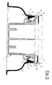
- the lighting device consists of a containment body 1 of the light source (not shown), having a cylindrical form and closed on the bottom, but which can also have the form of a prism, a covering plate 2 made of glass or another transparent material having the necessary resistance, which covers the containment body 1 and an outer casing 3, whose upper portion reproduces the form and is slightly larger than the containment body 1 and whose lower portion is wider to allow a better distribution of the forces which can burden the structure, for example weight due to the passage of a pedestrian or car over the lighting device.
- the containment body 1 defines a space for the housing of a light source and has an opening 4 for the passage of the electric supply wire.
- the containment body 1 can be equipped with two openings 4 for the passage of the electric supply wire, to facilitate the cascade wiring of several lighting devices without requiring the preparation of external electric connections.
- the hydraulic seal in correspondence with the opening 4 is obtained by a wire clip (not shown).
- the upper end of the containment body 1 is equipped with a flange 7 which has the function of collaborating with the coupling of the containment body 1 with the covering plate 2.
- the covering plate 2 is made integral, by means of siliconing or with a suitable adhesive which is capable of ensuring the necessary hydraulic and also mechanical seal, to a supporting ring 8, applied on the lower surface of the covering plate 2 and which substantially reproduces the form of the flange 7 of the containment body 1 and, at the same time, the perimeter of the covering plate 2.
- a sealing layer 9 between the covering plate 2 and the supporting ring 8.
- the supporting ring 8 is equipped, on its lower surface, with pins 10, of which at least the end is threaded and which form studs on which, after passing through the holes 11 of the flange 7, nuts or rounded screws 12 are applied, which fix the supporting ring 8, and together with this the covering plate 2, to the containment body 1.
- the upper surface of the covering plate 2 remains completely free from fixing elements and can be produced so that it represents the only part of the lighting device which remains visible from the outside of the floor or wall in which the lighting device is inserted.
- the coupling between the covering plate 2 and the supporting ring 8 is obtained with adhesive means capable of ensuring the hydraulic seal.
- adhesive means capable of ensuring the hydraulic seal.
- a washer 13 is arranged between the supporting ring 8 and the flange 7 of the containment body 1, which has the form of a ring and is made of an elastic material with a surface equipped with grooves 14, for improving the sealing effect, and holes 15, for the passage of the pins 10.
- a collar 16 is applied on the upper portion of the outer casing 3, which surrounds the upper part of the outer casing 3 but also the flange 7 of the containment body 1, the washer 13, the supporting ring 8, the sealing layer 9 and the covering plate 2.
- the collar 16 is applied to the upper portion of the outer side surface of the outer casing 3 by means of a series of screws 17.
- perimetric reliefs 18 are situated on the washer 13, which interfere with the inner surface of the collar 16.
- perimetric reliefs 18 it is possible to have a single relief on the side surface of the washer 13, which runs along the whole perimeter of the washer 13 and is in contact with interference along the whole inner perimeter of the collar 16.
- the lighting device of the present invention allows, without requiring modifications of its structure, the optional application of known devices such as, for example: means for maintaining the temperature of the surface exposed to the outside at values lower than those prescribed by safety regulations, anti-dazzle means, filters, refractors, pictograms.
- the covering plate 2 can also be made of anti-slip glass.
- the lighting device object of the present invention, has the advantage of only having the surface of the covering plate 2 towards the outside, i.e. of having a surface entirely destined for the passage of light, and it allows the surface at the disposal of the lighting device to be exploited in order to obtain the maximum lighting surface. Furthermore, the visible surface of the lighting device is uniform, also responding to criteria of an aesthetical nature.
- the built-in lighting device of the present invention is also exactly in line with the surface of the floor, road paving or wall in which it is inserted, providing further advantages, such as, for example, in applications for road surfaces, the possibility of application in roads in which the use of snowploughs may be necessary, without of the risk of the blade, which moves the snow sideways, striking against any possible protruding portions of the device.
- the built-in lighting device of the present invention can be easily opened for inspections, maintenance or for any necessary requirement.
Landscapes
- Engineering & Computer Science (AREA)
- General Engineering & Computer Science (AREA)
- Non-Portable Lighting Devices Or Systems Thereof (AREA)
- Arrangement Of Elements, Cooling, Sealing, Or The Like Of Lighting Devices (AREA)
- Securing Globes, Refractors, Reflectors Or The Like (AREA)
Applications Claiming Priority (1)
| Application Number | Priority Date | Filing Date | Title |
|---|---|---|---|
| IT000124U ITMI20050124U1 (it) | 2005-04-08 | 2005-04-08 | Dispositivo di illuminazione da incasso a pavimento o parete con superficie esterna completamente in vetro |
Publications (3)
| Publication Number | Publication Date |
|---|---|
| EP1710490A2 true EP1710490A2 (de) | 2006-10-11 |
| EP1710490A3 EP1710490A3 (de) | 2008-06-25 |
| EP1710490B1 EP1710490B1 (de) | 2010-06-02 |
Family
ID=36129888
Family Applications (1)
| Application Number | Title | Priority Date | Filing Date |
|---|---|---|---|
| EP06111489A Expired - Lifetime EP1710490B1 (de) | 2005-04-08 | 2006-03-21 | Boden-oder Wandeinbauleuchte mit einer vollkommen aus Glas bestehenden Aussenfläche |
Country Status (7)
| Country | Link |
|---|---|
| EP (1) | EP1710490B1 (de) |
| CN (1) | CN100554770C (de) |
| AT (1) | ATE470105T1 (de) |
| DE (1) | DE602006014614D1 (de) |
| ES (1) | ES2347170T3 (de) |
| IT (1) | ITMI20050124U1 (de) |
| NO (1) | NO20061495L (de) |
Cited By (1)
| Publication number | Priority date | Publication date | Assignee | Title |
|---|---|---|---|---|
| DE102020101078B3 (de) | 2020-01-17 | 2021-07-22 | Rzb Rudolf Zimmermann, Bamberg Gmbh | Einbaudeckenring mit Innenleuchte |
Citations (1)
| Publication number | Priority date | Publication date | Assignee | Title |
|---|---|---|---|---|
| WO2002044614A1 (de) | 2000-11-29 | 2002-06-06 | Zumtobel Staff Gmbh | Leuchte mit einer abdeckscheibe |
Family Cites Families (8)
| Publication number | Priority date | Publication date | Assignee | Title |
|---|---|---|---|---|
| FR1582188A (de) * | 1968-07-17 | 1969-09-26 | ||
| US5390090A (en) * | 1991-12-09 | 1995-02-14 | Nau; Larry J. | Ground supported lamp |
| US5481443A (en) * | 1993-05-19 | 1996-01-02 | The Genlyte Group, Inc. | In-ground directional light fixture |
| DE9318608U1 (de) * | 1993-12-04 | 1994-02-10 | Zicoli-Leuchten Zimmermann & Co. GmbH, 74838 Limbach | Verteiler zur Montage an Decken oder Wänden |
| CN2240664Y (zh) * | 1995-06-07 | 1996-11-20 | 周昱 | 一种彩色水地多用灯 |
| DE10156325B4 (de) * | 2001-11-19 | 2006-10-05 | Trilux-Lenze Gmbh + Co Kg | Vorrichtung zur Befestigung einer ein Leuchtgehäuse abschließenden Scheibe |
| CN2524078Y (zh) * | 2001-11-28 | 2002-12-04 | 黄忠国 | 一种地灯 |
| CN2676022Y (zh) * | 2004-01-09 | 2005-02-02 | 深圳市沃科半导体照明有限公司 | 埋地灯 |
-
2005
- 2005-04-08 IT IT000124U patent/ITMI20050124U1/it unknown
-
2006
- 2006-03-21 ES ES06111489T patent/ES2347170T3/es not_active Expired - Lifetime
- 2006-03-21 AT AT06111489T patent/ATE470105T1/de not_active IP Right Cessation
- 2006-03-21 DE DE602006014614T patent/DE602006014614D1/de not_active Expired - Lifetime
- 2006-03-21 EP EP06111489A patent/EP1710490B1/de not_active Expired - Lifetime
- 2006-04-03 NO NO20061495A patent/NO20061495L/no not_active Application Discontinuation
- 2006-04-07 CN CNB2006100733116A patent/CN100554770C/zh not_active Expired - Fee Related
Patent Citations (1)
| Publication number | Priority date | Publication date | Assignee | Title |
|---|---|---|---|---|
| WO2002044614A1 (de) | 2000-11-29 | 2002-06-06 | Zumtobel Staff Gmbh | Leuchte mit einer abdeckscheibe |
Cited By (1)
| Publication number | Priority date | Publication date | Assignee | Title |
|---|---|---|---|---|
| DE102020101078B3 (de) | 2020-01-17 | 2021-07-22 | Rzb Rudolf Zimmermann, Bamberg Gmbh | Einbaudeckenring mit Innenleuchte |
Also Published As
| Publication number | Publication date |
|---|---|
| EP1710490B1 (de) | 2010-06-02 |
| ATE470105T1 (de) | 2010-06-15 |
| CN100554770C (zh) | 2009-10-28 |
| NO20061495L (no) | 2006-10-09 |
| ES2347170T3 (es) | 2010-10-26 |
| ITMI20050124U1 (it) | 2006-10-09 |
| DE602006014614D1 (de) | 2010-07-15 |
| EP1710490A3 (de) | 2008-06-25 |
| CN1844734A (zh) | 2006-10-11 |
Similar Documents
| Publication | Publication Date | Title |
|---|---|---|
| US8881468B2 (en) | Fixture wall mount assembly with integral flashing | |
| AU2015203173B2 (en) | Lighted rail for a false wall with a stretched canvas and false wall comprising such a rail | |
| ATE443232T1 (de) | Einbauleuchte mit einem haltering für zusatzbauteile | |
| KR101865158B1 (ko) | 공동주택 건축물용 외벽 전기 케이블 안전장치 | |
| EP1710490B1 (de) | Boden-oder Wandeinbauleuchte mit einer vollkommen aus Glas bestehenden Aussenfläche | |
| WO2007013121A1 (en) | Led-based lighting device for ground, wall, floor and road surface mounting | |
| EP1686315B1 (de) | Feuerfeste Abdeckung für eine Leuchte | |
| KR101126586B1 (ko) | 조명장치의 밀봉구조 | |
| KR102249450B1 (ko) | 각도가변식 경관등 | |
| CA2919802C (en) | Easy install light engine retrofit kit and method for using same | |
| KR200335458Y1 (ko) | 스위치 커버용 벽면 보호판 | |
| JP3500818B2 (ja) | 照明器具 | |
| KR100961073B1 (ko) | 스피커가 내장된 천장매입형 형광등기구 | |
| KR101721141B1 (ko) | 가로등 램프 | |
| KR102588186B1 (ko) | 건축용 통신단자함 방수구조 | |
| KR101874964B1 (ko) | 엘이디 등기구 | |
| RU2782163C1 (ru) | Светодиодный столбик | |
| KR200385777Y1 (ko) | 천장 조명등 지지구 | |
| GB2286930A (en) | An electrical accessory mounting | |
| CN212108052U (zh) | 防油防水照明灯及油烟机 | |
| KR200230332Y1 (ko) | 방탄 이중 점검창 부착형 버터플라이 밸브 | |
| CN205938788U (zh) | 一种新型泛光灯 | |
| GB2620640A (en) | Adjustable downlight | |
| CN121195132A (zh) | 用于背光控制的护罩 | |
| KR200293629Y1 (ko) | 가습기용 램프구조 |
Legal Events
| Date | Code | Title | Description |
|---|---|---|---|
| PUAI | Public reference made under article 153(3) epc to a published international application that has entered the european phase |
Free format text: ORIGINAL CODE: 0009012 |
|
| AK | Designated contracting states |
Kind code of ref document: A2 Designated state(s): AT BE BG CH CY CZ DE DK EE ES FI FR GB GR HU IE IS IT LI LT LU LV MC NL PL PT RO SE SI SK TR |
|
| AX | Request for extension of the european patent |
Extension state: AL BA HR MK YU |
|
| PUAL | Search report despatched |
Free format text: ORIGINAL CODE: 0009013 |
|
| AK | Designated contracting states |
Kind code of ref document: A3 Designated state(s): AT BE BG CH CY CZ DE DK EE ES FI FR GB GR HU IE IS IT LI LT LU LV MC NL PL PT RO SE SI SK TR |
|
| AX | Request for extension of the european patent |
Extension state: AL BA HR MK YU |
|
| 17P | Request for examination filed |
Effective date: 20080919 |
|
| AKX | Designation fees paid |
Designated state(s): AT BE BG CH CY CZ DE DK EE ES FI FR GB GR HU IE IS IT LI LT LU LV MC NL PL PT RO SE SI SK TR |
|
| GRAP | Despatch of communication of intention to grant a patent |
Free format text: ORIGINAL CODE: EPIDOSNIGR1 |
|
| GRAS | Grant fee paid |
Free format text: ORIGINAL CODE: EPIDOSNIGR3 |
|
| GRAA | (expected) grant |
Free format text: ORIGINAL CODE: 0009210 |
|
| AK | Designated contracting states |
Kind code of ref document: B1 Designated state(s): AT BE BG CH CY CZ DE DK EE ES FI FR GB GR HU IE IS IT LI LT LU LV MC NL PL PT RO SE SI SK TR |
|
| REG | Reference to a national code |
Ref country code: GB Ref legal event code: FG4D |
|
| REG | Reference to a national code |
Ref country code: CH Ref legal event code: EP |
|
| REG | Reference to a national code |
Ref country code: IE Ref legal event code: FG4D |
|
| REF | Corresponds to: |
Ref document number: 602006014614 Country of ref document: DE Date of ref document: 20100715 Kind code of ref document: P |
|
| REG | Reference to a national code |
Ref country code: NL Ref legal event code: VDEP Effective date: 20100602 |
|
| REG | Reference to a national code |
Ref country code: ES Ref legal event code: FG2A Ref document number: 2347170 Country of ref document: ES Kind code of ref document: T3 |
|
| PG25 | Lapsed in a contracting state [announced via postgrant information from national office to epo] |
Ref country code: SE Free format text: LAPSE BECAUSE OF FAILURE TO SUBMIT A TRANSLATION OF THE DESCRIPTION OR TO PAY THE FEE WITHIN THE PRESCRIBED TIME-LIMIT Effective date: 20100602 Ref country code: LT Free format text: LAPSE BECAUSE OF FAILURE TO SUBMIT A TRANSLATION OF THE DESCRIPTION OR TO PAY THE FEE WITHIN THE PRESCRIBED TIME-LIMIT Effective date: 20100602 |
|
| LTIE | Lt: invalidation of european patent or patent extension |
Effective date: 20100602 |
|
| PG25 | Lapsed in a contracting state [announced via postgrant information from national office to epo] |
Ref country code: AT Free format text: LAPSE BECAUSE OF FAILURE TO SUBMIT A TRANSLATION OF THE DESCRIPTION OR TO PAY THE FEE WITHIN THE PRESCRIBED TIME-LIMIT Effective date: 20100602 Ref country code: LV Free format text: LAPSE BECAUSE OF FAILURE TO SUBMIT A TRANSLATION OF THE DESCRIPTION OR TO PAY THE FEE WITHIN THE PRESCRIBED TIME-LIMIT Effective date: 20100602 Ref country code: SI Free format text: LAPSE BECAUSE OF FAILURE TO SUBMIT A TRANSLATION OF THE DESCRIPTION OR TO PAY THE FEE WITHIN THE PRESCRIBED TIME-LIMIT Effective date: 20100602 Ref country code: FI Free format text: LAPSE BECAUSE OF FAILURE TO SUBMIT A TRANSLATION OF THE DESCRIPTION OR TO PAY THE FEE WITHIN THE PRESCRIBED TIME-LIMIT Effective date: 20100602 |
|
| PG25 | Lapsed in a contracting state [announced via postgrant information from national office to epo] |
Ref country code: GR Free format text: LAPSE BECAUSE OF FAILURE TO SUBMIT A TRANSLATION OF THE DESCRIPTION OR TO PAY THE FEE WITHIN THE PRESCRIBED TIME-LIMIT Effective date: 20100903 Ref country code: PL Free format text: LAPSE BECAUSE OF FAILURE TO SUBMIT A TRANSLATION OF THE DESCRIPTION OR TO PAY THE FEE WITHIN THE PRESCRIBED TIME-LIMIT Effective date: 20100602 Ref country code: CY Free format text: LAPSE BECAUSE OF FAILURE TO SUBMIT A TRANSLATION OF THE DESCRIPTION OR TO PAY THE FEE WITHIN THE PRESCRIBED TIME-LIMIT Effective date: 20100602 |
|
| PG25 | Lapsed in a contracting state [announced via postgrant information from national office to epo] |
Ref country code: EE Free format text: LAPSE BECAUSE OF FAILURE TO SUBMIT A TRANSLATION OF THE DESCRIPTION OR TO PAY THE FEE WITHIN THE PRESCRIBED TIME-LIMIT Effective date: 20100602 Ref country code: NL Free format text: LAPSE BECAUSE OF FAILURE TO SUBMIT A TRANSLATION OF THE DESCRIPTION OR TO PAY THE FEE WITHIN THE PRESCRIBED TIME-LIMIT Effective date: 20100602 |
|
| PG25 | Lapsed in a contracting state [announced via postgrant information from national office to epo] |
Ref country code: BE Free format text: LAPSE BECAUSE OF FAILURE TO SUBMIT A TRANSLATION OF THE DESCRIPTION OR TO PAY THE FEE WITHIN THE PRESCRIBED TIME-LIMIT Effective date: 20100602 Ref country code: SK Free format text: LAPSE BECAUSE OF FAILURE TO SUBMIT A TRANSLATION OF THE DESCRIPTION OR TO PAY THE FEE WITHIN THE PRESCRIBED TIME-LIMIT Effective date: 20100602 Ref country code: PT Free format text: LAPSE BECAUSE OF FAILURE TO SUBMIT A TRANSLATION OF THE DESCRIPTION OR TO PAY THE FEE WITHIN THE PRESCRIBED TIME-LIMIT Effective date: 20101004 Ref country code: CZ Free format text: LAPSE BECAUSE OF FAILURE TO SUBMIT A TRANSLATION OF THE DESCRIPTION OR TO PAY THE FEE WITHIN THE PRESCRIBED TIME-LIMIT Effective date: 20100602 Ref country code: IS Free format text: LAPSE BECAUSE OF FAILURE TO SUBMIT A TRANSLATION OF THE DESCRIPTION OR TO PAY THE FEE WITHIN THE PRESCRIBED TIME-LIMIT Effective date: 20101002 Ref country code: RO Free format text: LAPSE BECAUSE OF FAILURE TO SUBMIT A TRANSLATION OF THE DESCRIPTION OR TO PAY THE FEE WITHIN THE PRESCRIBED TIME-LIMIT Effective date: 20100602 |
|
| PLBE | No opposition filed within time limit |
Free format text: ORIGINAL CODE: 0009261 |
|
| STAA | Information on the status of an ep patent application or granted ep patent |
Free format text: STATUS: NO OPPOSITION FILED WITHIN TIME LIMIT |
|
| PG25 | Lapsed in a contracting state [announced via postgrant information from national office to epo] |
Ref country code: DK Free format text: LAPSE BECAUSE OF FAILURE TO SUBMIT A TRANSLATION OF THE DESCRIPTION OR TO PAY THE FEE WITHIN THE PRESCRIBED TIME-LIMIT Effective date: 20100602 |
|
| 26N | No opposition filed |
Effective date: 20110303 |
|
| REG | Reference to a national code |
Ref country code: DE Ref legal event code: R097 Ref document number: 602006014614 Country of ref document: DE Effective date: 20110302 |
|
| PG25 | Lapsed in a contracting state [announced via postgrant information from national office to epo] |
Ref country code: MC Free format text: LAPSE BECAUSE OF NON-PAYMENT OF DUE FEES Effective date: 20110331 |
|
| REG | Reference to a national code |
Ref country code: CH Ref legal event code: PL |
|
| REG | Reference to a national code |
Ref country code: IE Ref legal event code: MM4A |
|
| PG25 | Lapsed in a contracting state [announced via postgrant information from national office to epo] |
Ref country code: LI Free format text: LAPSE BECAUSE OF NON-PAYMENT OF DUE FEES Effective date: 20110331 Ref country code: IE Free format text: LAPSE BECAUSE OF NON-PAYMENT OF DUE FEES Effective date: 20110321 Ref country code: CH Free format text: LAPSE BECAUSE OF NON-PAYMENT OF DUE FEES Effective date: 20110331 |
|
| PG25 | Lapsed in a contracting state [announced via postgrant information from national office to epo] |
Ref country code: LU Free format text: LAPSE BECAUSE OF NON-PAYMENT OF DUE FEES Effective date: 20110321 |
|
| PG25 | Lapsed in a contracting state [announced via postgrant information from national office to epo] |
Ref country code: TR Free format text: LAPSE BECAUSE OF FAILURE TO SUBMIT A TRANSLATION OF THE DESCRIPTION OR TO PAY THE FEE WITHIN THE PRESCRIBED TIME-LIMIT Effective date: 20100602 Ref country code: BG Free format text: LAPSE BECAUSE OF FAILURE TO SUBMIT A TRANSLATION OF THE DESCRIPTION OR TO PAY THE FEE WITHIN THE PRESCRIBED TIME-LIMIT Effective date: 20100902 |
|
| PG25 | Lapsed in a contracting state [announced via postgrant information from national office to epo] |
Ref country code: HU Free format text: LAPSE BECAUSE OF FAILURE TO SUBMIT A TRANSLATION OF THE DESCRIPTION OR TO PAY THE FEE WITHIN THE PRESCRIBED TIME-LIMIT Effective date: 20100602 |
|
| REG | Reference to a national code |
Ref country code: FR Ref legal event code: PLFP Year of fee payment: 11 |
|
| REG | Reference to a national code |
Ref country code: FR Ref legal event code: PLFP Year of fee payment: 12 |
|
| REG | Reference to a national code |
Ref country code: FR Ref legal event code: PLFP Year of fee payment: 13 |
|
| PGFP | Annual fee paid to national office [announced via postgrant information from national office to epo] |
Ref country code: FR Payment date: 20230328 Year of fee payment: 18 |
|
| PGFP | Annual fee paid to national office [announced via postgrant information from national office to epo] |
Ref country code: GB Payment date: 20230316 Year of fee payment: 18 |
|
| P01 | Opt-out of the competence of the unified patent court (upc) registered |
Effective date: 20230525 |
|
| PGFP | Annual fee paid to national office [announced via postgrant information from national office to epo] |
Ref country code: ES Payment date: 20230405 Year of fee payment: 18 |
|
| GBPC | Gb: european patent ceased through non-payment of renewal fee |
Effective date: 20240321 |
|
| PG25 | Lapsed in a contracting state [announced via postgrant information from national office to epo] |
Ref country code: GB Free format text: LAPSE BECAUSE OF NON-PAYMENT OF DUE FEES Effective date: 20240321 |
|
| PG25 | Lapsed in a contracting state [announced via postgrant information from national office to epo] |
Ref country code: FR Free format text: LAPSE BECAUSE OF NON-PAYMENT OF DUE FEES Effective date: 20240331 |
|
| PG25 | Lapsed in a contracting state [announced via postgrant information from national office to epo] |
Ref country code: GB Free format text: LAPSE BECAUSE OF NON-PAYMENT OF DUE FEES Effective date: 20240321 Ref country code: FR Free format text: LAPSE BECAUSE OF NON-PAYMENT OF DUE FEES Effective date: 20240331 |
|
| PGFP | Annual fee paid to national office [announced via postgrant information from national office to epo] |
Ref country code: DE Payment date: 20250225 Year of fee payment: 20 |
|
| REG | Reference to a national code |
Ref country code: ES Ref legal event code: FD2A Effective date: 20250430 |
|
| PG25 | Lapsed in a contracting state [announced via postgrant information from national office to epo] |
Ref country code: ES Free format text: LAPSE BECAUSE OF NON-PAYMENT OF DUE FEES Effective date: 20240322 |
|
| PGFP | Annual fee paid to national office [announced via postgrant information from national office to epo] |
Ref country code: IT Payment date: 20250331 Year of fee payment: 20 |
|
| REG | Reference to a national code |
Ref country code: DE Ref legal event code: R071 Ref document number: 602006014614 Country of ref document: DE |