EP1710509A2 - Raccord de tuyaux - Google Patents
Raccord de tuyaux Download PDFInfo
- Publication number
- EP1710509A2 EP1710509A2 EP06110375A EP06110375A EP1710509A2 EP 1710509 A2 EP1710509 A2 EP 1710509A2 EP 06110375 A EP06110375 A EP 06110375A EP 06110375 A EP06110375 A EP 06110375A EP 1710509 A2 EP1710509 A2 EP 1710509A2
- Authority
- EP
- European Patent Office
- Prior art keywords
- tubular body
- inlet
- piping
- outlet
- union
- Prior art date
- Legal status (The legal status is an assumption and is not a legal conclusion. Google has not performed a legal analysis and makes no representation as to the accuracy of the status listed.)
- Granted
Links
- 239000012530 fluid Substances 0.000 claims abstract description 12
- 238000007789 sealing Methods 0.000 claims description 9
- 238000009428 plumbing Methods 0.000 description 7
- 238000010438 heat treatment Methods 0.000 description 6
- 238000012423 maintenance Methods 0.000 description 4
- 230000008878 coupling Effects 0.000 description 3
- 238000010168 coupling process Methods 0.000 description 3
- 238000005859 coupling reaction Methods 0.000 description 3
- XLYOFNOQVPJJNP-UHFFFAOYSA-N water Substances O XLYOFNOQVPJJNP-UHFFFAOYSA-N 0.000 description 3
- 238000003466 welding Methods 0.000 description 3
- 230000008901 benefit Effects 0.000 description 2
- 230000000694 effects Effects 0.000 description 2
- 238000012545 processing Methods 0.000 description 2
- 241001272720 Medialuna californiensis Species 0.000 description 1
- 230000009471 action Effects 0.000 description 1
- 238000005452 bending Methods 0.000 description 1
- 239000000463 material Substances 0.000 description 1
- 230000007246 mechanism Effects 0.000 description 1
- 238000012986 modification Methods 0.000 description 1
- 230000004048 modification Effects 0.000 description 1
- 230000002441 reversible effect Effects 0.000 description 1
- 238000011144 upstream manufacturing Methods 0.000 description 1
Images




Classifications
-
- F—MECHANICAL ENGINEERING; LIGHTING; HEATING; WEAPONS; BLASTING
- F24—HEATING; RANGES; VENTILATING
- F24D—DOMESTIC- OR SPACE-HEATING SYSTEMS, e.g. CENTRAL HEATING SYSTEMS; DOMESTIC HOT-WATER SUPPLY SYSTEMS; ELEMENTS OR COMPONENTS THEREFOR
- F24D19/00—Details
- F24D19/0002—Means for connecting central heating radiators to circulation pipes
-
- F—MECHANICAL ENGINEERING; LIGHTING; HEATING; WEAPONS; BLASTING
- F16—ENGINEERING ELEMENTS AND UNITS; GENERAL MEASURES FOR PRODUCING AND MAINTAINING EFFECTIVE FUNCTIONING OF MACHINES OR INSTALLATIONS; THERMAL INSULATION IN GENERAL
- F16L—PIPES; JOINTS OR FITTINGS FOR PIPES; SUPPORTS FOR PIPES, CABLES OR PROTECTIVE TUBING; MEANS FOR THERMAL INSULATION IN GENERAL
- F16L41/00—Branching pipes; Joining pipes to walls
- F16L41/02—Branch units, e.g. made in one piece, welded, riveted
-
- F—MECHANICAL ENGINEERING; LIGHTING; HEATING; WEAPONS; BLASTING
- F16—ENGINEERING ELEMENTS AND UNITS; GENERAL MEASURES FOR PRODUCING AND MAINTAINING EFFECTIVE FUNCTIONING OF MACHINES OR INSTALLATIONS; THERMAL INSULATION IN GENERAL
- F16L—PIPES; JOINTS OR FITTINGS FOR PIPES; SUPPORTS FOR PIPES, CABLES OR PROTECTIVE TUBING; MEANS FOR THERMAL INSULATION IN GENERAL
- F16L41/00—Branching pipes; Joining pipes to walls
- F16L41/08—Joining pipes to walls or pipes, the joined pipe axis being perpendicular to the plane of a wall or to the axis of another pipe
- F16L41/14—Joining pipes to walls or pipes, the joined pipe axis being perpendicular to the plane of a wall or to the axis of another pipe by screwing an intermediate part against the inside or outside of the wall
-
- F—MECHANICAL ENGINEERING; LIGHTING; HEATING; WEAPONS; BLASTING
- F28—HEAT EXCHANGE IN GENERAL
- F28F—DETAILS OF HEAT-EXCHANGE AND HEAT-TRANSFER APPARATUS, OF GENERAL APPLICATION
- F28F9/00—Casings; Header boxes; Auxiliary supports for elements; Auxiliary members within casings
- F28F9/26—Arrangements for connecting different sections of heat-exchange elements, e.g. of radiators
- F28F9/262—Arrangements for connecting different sections of heat-exchange elements, e.g. of radiators for radiators
- F28F9/266—Arrangements for connecting different sections of heat-exchange elements, e.g. of radiators for radiators by screw-type connections
Definitions
- the aim of the present invention is a piping union.
- Piping unions are generally used in the heating plants (of rooms in housing and commercial buildings or of other type) in order to operably connect piping suitable for the transport of a fluid, generally hot water.
- the piping unions can be employed on radiating elements characterized by at least two parallel horizontal manifolds for connecting the manifolds themselves, so as to supply an adequate feed with the fluid coming from the plumbing.
- the invention will be described with reference to this type of application, even if, of course, it could find an application in any other plant in which it is required the joining of piping.
- the technical problem at the basis of the present invention is represented by the need of properly feeding with the hot water coming from the piping of a plumbing a radiating element (usually called radiator or heating element) having more than one manifold in parallel.
- a radiating element usually called radiator or heating element
- Such radiating elements can consist of a single piece or being obtained by welding two or more radiating elements, each equipped with an own manifold. They have a heating surface greater than the conventional radiating elements and therefore are useful for the heating of environments in which the spaces intended for the radiating elements are narrow (for example in case of rooms having windows placed at a reduced height from the floor).
- a second known solution is to provide the plumbing with multiple discharge and return piping, so as to operably connect each manifold of the radiating element with one of these piping.
- the aim of the present invention is to overcome the drawbacks above complained. Therefore, the aim of the invention is to present a piping union which is compatible with the conventional heating plants and which allows an easy management of the temperature of the room to be heated.
- a further aim of the invention is to provide a fitting for radiating elements having more than two parallel manifolds. Moreover, an aim of the present invention is to join the manifolds of radiating elements placed at any distance from each other.
- an aim of the invention is to show a pipe fitting which is easy to produce and inexpensive and which gives a pleasant aesthetical effect to the radiating element.
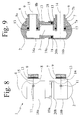
- a piping union 1 includes a main body 2, having a passage 3 for the fluid coming from such piping, equipped with at least an inlet 4 and at least an outlet 5.
- the union 1 further presents at least an inlet tubular body 7 and at least an outlet tubular body 8, respectively associable with the inlet 4 and the outlet 5 of the passage 3 of the main body 2.
- Such inlet and outlet tubular bodies 7, 8 are fitted in the main body 2, in particular in such a way that the main axis 6 of the main body 2 is perpendicular to the main axes 14, 15 of the two tubular bodies 7, 8.
- the main exes 14, 15 of the two tubular bodies 7, 8, when inserted in the main body 2, are in turn parallel therebetween.
- the portion 7a, 8a of the tubular bodies 7, 8 which contacts the main body 2 is advantageously equipped with first sealing gaskets 13, for example 0-rings, for improving the fastening between the different bodies 2, 7, 8 and avoiding any water leakages in the environment to be heated, which would also lead to a faster wear of the union 1 itself.
- first sealing gaskets 13 for example 0-rings
- fastening means 10 are generally represented by grub screws which are screwed, preferably using an Allen wrench, in proper through-seats 11 having a thread 12, obtained in the main body 2 for carrying out a pusher action on the tubular bodies 7, 8.
- this kind of mounting allows to disconnect at any time the tubular bodies 7, 8 from the main body 2 for performing maintenance operations, such as the replacement of the first sealing gaskets 13 or for changing the configuration of the radiating element itself.
- the number of tubular bodies 7, 8 which can be inserted in the main body 2, and therefore the total number of inlets 4 and outlets 5 of the passage 3 of the main body 2 is equal to the number of horizontal manifolds included in the radiating element on which the union is to be carried out.
- the tubular bodies 7, 8 are directly associable to the manifolds of the radiating elements.
- the fluid falls through the vertical tubes of the radiating element towards the second down manifold where, through the second fitting 1 reaches the first lower collector, which also collects the fluid falling from the vertical tubes connected with the first upper collector and, after having cross it, returns in the plumbing.
- a radiating element with three horizontal manifolds is equipped with a first fitting 1 associated with the upper manifolds having an inlet 4 and two outlets 5 and a second fitting 1 mounted on the lower manifolds having two inlets 4 and an outlet 5.
- the main body 2 is formed by at least two secondary bodies 16 associable therebetween, each containing the inlet 4 or the outlet 5 of the fluid passage 3.
- the union 1 can be mounted on any radiating element independently of the existing distance between the parallel horizontal manifolds. Such distance, in fact, is not conventionally fixed, as the radiating elements of this type have a reduced market share and as they can also be formed by two or more radiating elements welded together.
- a piping union 1 according to the second embodiment consists of two or more secondary bodies 16 telescopically associable for adjusting the distance between the inlet and outlet tubular bodies 7, 8.
- the secondary bodies 16 are associated as fitting. Therefore, for example, when the main body 2 of the union 1 consists of two secondary bodies 16a, 16b, a first secondary body 16a is equipped with an end portion 19a of a smaller diameter with respect to the diameter of a second secondary body 16b, so as to allow such end portion 19a to be inserted in a seat 20b foreseen in this second secondary body 16b.
- this end portion 19a suitable for being inserted within the second secondary body 16b is equipped with second sealing gaskets 18, for example 0-rings, for preventing leakages of fluid from the passage 3.
- the coupling between the secondary bodies 16a, 16b is structured so as to allow a following disassembling which permits, for example, to carry out maintenance operations.
- the number of secondary bodies 16 is equal to the number of tubular bodies 7, 8 and the number of horizontal manifolds of the radiating element on which it is mounted.
- the inlet and outlet tubular bodies 7, 8 are screwed to the manifolds of a radiating element, then the main body 2 is formed by mounting the secondary bodies 16 which composes it and by adjusting the distance based on the distance of the manifolds of the radiating element and, finally, one proceeds to the mounting of the main body 2 on the tubular bodies 7, 8 by further adjusting the fastening between the secondary bodies 16, if necessary.
- the third embodiment of the union 1, based on a principle very similar to the second one, further includes at least a connecting body 17, through which the two or more secondary bodies 16 are mutually associable.
- each secondary body 16 results telescopically connected to a connecting body 17 always for adapting the union 1 to any distance between the manifolds of the radiating element.
- each secondary body 16 is equipped with a seat 20 in at least an end portion 21 thereof, in which the connecting body 17 is fitted for forming the structure of the main body 2.
- second sealing gaskets 18 for example 0-rings which prevent the leakage of fluid from the passage 3, preferably placed in correspondence with the portions of the connecting body 17 which are inserted in the secondary bodies 16.
- the union 1 after the mounting on the radiating element, the union 1 can be disassembled for performing maintenance operations.
- a main body 2 according to this third embodiment includes a number of secondary bodies 16 equal to the number of horizontal manifolds of the radiating element on which it is mounted and a number of connecting bodies 17 equal to the number of secondary bodies 16 less one.
- the assembly of this kind of unions 1 follows the preceding one. Indeed, after having screwed the tubular bodies 7, 8 to the manifolds of the radiating element, the main body 2 is carried out by mounting the secondary bodies 16 on the connecting bodies 17 and adjusting the distance thereof. Subsequently, such main body 2 is fixed as a joint on the tubular bodies 7, 8, preferably by also using the fastening means 10 and the adjustment previously carried out on the telescopic mechanism is improved.
- the invention attains important advantages.
- the union above described is utilizable with all the heating plants commonly carried out and can be directly mounted on the radiating elements without the need of further processings, which would negatively weigh on the costs.
- the possibility of a telescopic adjustment of the main body length allows to adapt the union to any kind of radiating element having more than one horizontal manifold.
- a further advantage is that the union of the invention easily allows to join together more than two manifolds and therefore it can be also used on radiating elements of large dimensions.
- the couplings between the different components of the union are reversible so as to make easier the maintenance operations, for example.
- the union shown by the invention is also advantageous because it has a pleasant impact on the aesthetic of the radiating element.
- a radiating element equipped with the shown union has the same operation principle than a conventional radiating element and therefore, for example, the temperature of the room to be heated can easily be adjusted by a thermostatic valve placed on the connection between the discharge piping of the plant and the radiating element.
Landscapes
- Engineering & Computer Science (AREA)
- General Engineering & Computer Science (AREA)
- Mechanical Engineering (AREA)
- Physics & Mathematics (AREA)
- Thermal Sciences (AREA)
- Chemical & Material Sciences (AREA)
- Combustion & Propulsion (AREA)
- Branch Pipes, Bends, And The Like (AREA)
- Quick-Acting Or Multi-Walled Pipe Joints (AREA)
Applications Claiming Priority (1)
| Application Number | Priority Date | Filing Date | Title |
|---|---|---|---|
| ITBS20050025 ITBS20050025A1 (it) | 2005-02-28 | 2005-02-28 | Raccordo per tubazioni |
Publications (3)
| Publication Number | Publication Date |
|---|---|
| EP1710509A2 true EP1710509A2 (fr) | 2006-10-11 |
| EP1710509A3 EP1710509A3 (fr) | 2007-02-14 |
| EP1710509B1 EP1710509B1 (fr) | 2016-02-03 |
Family
ID=36484415
Family Applications (1)
| Application Number | Title | Priority Date | Filing Date |
|---|---|---|---|
| EP06110375.0A Expired - Lifetime EP1710509B1 (fr) | 2005-02-28 | 2006-02-24 | Raccord de tuyaux |
Country Status (2)
| Country | Link |
|---|---|
| EP (1) | EP1710509B1 (fr) |
| IT (1) | ITBS20050025A1 (fr) |
Family Cites Families (9)
| Publication number | Priority date | Publication date | Assignee | Title |
|---|---|---|---|---|
| US2486141A (en) * | 1946-10-10 | 1949-10-25 | Mel Products Company | Diversion fitting for hot-water heating systems |
| IT8021903V0 (it) * | 1980-05-26 | 1980-05-26 | Giacomini Rubinetterie | Collettore per la distribuzione di fluidi, per esempio dell'acqua calda, in impianti di riscaldamento. |
| DE19711074A1 (de) * | 1997-03-18 | 1998-09-24 | Simplex Wilfer Gmbh & Co | Vorrichtung zum Anschluß eines Heizkörpers |
| DE29723433U1 (de) * | 1997-05-16 | 1998-09-17 | Honeywell Ag, 63067 Offenbach | 3-Wege-Mischer |
| US6447028B1 (en) * | 2000-08-18 | 2002-09-10 | Asco Controls, L.P. | Joint fitting |
| FR2815110B1 (fr) * | 2000-10-11 | 2006-02-17 | Renard Gerard | Ensemble de deux conduits de gaz chauds raccordes au moyen d'un coupleur, procede de raccordement et coupleur correspondant |
| US20040046385A1 (en) * | 2002-09-05 | 2004-03-11 | Sami Shemtov | Low profile junction box connector |
| AU2003230201A1 (en) * | 2003-04-10 | 2004-11-01 | Raffaele Bergamante | Hydraulic joint articulated device and use thereof with a heat radiator |
| US6957831B1 (en) * | 2003-12-17 | 2005-10-25 | Giant Factories Inc. | Nipple for hot water tank conduits |
-
2005
- 2005-02-28 IT ITBS20050025 patent/ITBS20050025A1/it unknown
-
2006
- 2006-02-24 EP EP06110375.0A patent/EP1710509B1/fr not_active Expired - Lifetime
Non-Patent Citations (1)
| Title |
|---|
| None |
Also Published As
| Publication number | Publication date |
|---|---|
| EP1710509B1 (fr) | 2016-02-03 |
| EP1710509A3 (fr) | 2007-02-14 |
| ITBS20050025A1 (it) | 2006-09-01 |
Similar Documents
| Publication | Publication Date | Title |
|---|---|---|
| US6684906B2 (en) | Quick connect/disconnect water faucet conduit assembly | |
| KR20100019511A (ko) | 워터 매니폴드 시스템 및 방법 | |
| US8109297B2 (en) | Valve arrangement for use with a water meter | |
| US20090223654A1 (en) | An installation unit in a heating or cooling system | |
| CN212962915U (zh) | 一种钢六柱散热器 | |
| EP1710509A2 (fr) | Raccord de tuyaux | |
| EP2681494B1 (fr) | Dispositif adaptateur pour relier un élément de radiateur à un système de plomberie | |
| EP0614061B1 (fr) | Dispositif de contrÔle pour échangeur de chaleur à plaques et échangeur de chaleur correspondant | |
| US6546898B1 (en) | Hydronic heating system and kit | |
| EP0693658A1 (fr) | Arrangement improuvé de soupape prévu pour l'installations de chauffage ainsi que pour chauffe-eau domestique | |
| EP0387569A1 (fr) | Raccord de tuyau monobloc à sept voies pour la connexion de tuyauteries hydrauliques | |
| HUT74794A (en) | Panel heating radiator | |
| CN211550862U (zh) | 一种管中管转换接头 | |
| EP1546611B1 (fr) | Collecteur pour systemes de chauffage central | |
| EP0675312A1 (fr) | Manifold de distribution double pour installations de chauffage d'eau d'un type standardisé | |
| EP1655550A1 (fr) | Dispositif de distribution de fluide de chauffage pour un radiateur à plaques | |
| JP2004019254A (ja) | 混合水栓の配管接続構造 | |
| CN220269479U (zh) | 一种分集水器 | |
| CN204239905U (zh) | 一种带管器具与房间内伸出管线连接的定位板 | |
| EP1420217B1 (fr) | Echangeur de chaleur à plaques avec des conduits de interconnection composés modulaires, qui sont par là variable en leur langueur, qui join le raccord centré avec le supérieure corps de vanne | |
| RU195496U1 (ru) | Радиатор отопления с нижним подключением со встроенным термостатическим клапаном | |
| EP0863372A1 (fr) | Dispositif hydraulique pour radiateur à plaques | |
| KR200299320Y1 (ko) | 난방용 온수분배기 | |
| CN201811439U (zh) | 燃气热水器出水嘴与出水管的连接结构 | |
| GB2393779A (en) | Central heating radiator |
Legal Events
| Date | Code | Title | Description |
|---|---|---|---|
| PUAI | Public reference made under article 153(3) epc to a published international application that has entered the european phase |
Free format text: ORIGINAL CODE: 0009012 |
|
| AK | Designated contracting states |
Kind code of ref document: A2 Designated state(s): AT BE BG CH CY CZ DE DK EE ES FI FR GB GR HU IE IS IT LI LT LU LV MC NL PL PT RO SE SI SK TR |
|
| AX | Request for extension of the european patent |
Extension state: AL BA HR MK YU |
|
| PUAL | Search report despatched |
Free format text: ORIGINAL CODE: 0009013 |
|
| AK | Designated contracting states |
Kind code of ref document: A3 Designated state(s): AT BE BG CH CY CZ DE DK EE ES FI FR GB GR HU IE IS IT LI LT LU LV MC NL PL PT RO SE SI SK TR |
|
| AX | Request for extension of the european patent |
Extension state: AL BA HR MK YU |
|
| RIC1 | Information provided on ipc code assigned before grant |
Ipc: F24H 9/12 20060101ALI20070109BHEP Ipc: F16L 41/08 20060101ALI20070109BHEP Ipc: F24D 3/10 20060101AFI20060901BHEP Ipc: F16L 41/10 20060101ALI20070109BHEP |
|
| 17P | Request for examination filed |
Effective date: 20070621 |
|
| AKX | Designation fees paid |
Designated state(s): AT BE BG CH CY CZ DE DK EE ES FI FR GB GR HU IE IS IT LI LT LU LV MC NL PL PT RO SE SI SK TR |
|
| 17Q | First examination report despatched |
Effective date: 20130429 |
|
| REG | Reference to a national code |
Ref country code: DE Ref legal event code: R079 Ref document number: 602006047867 Country of ref document: DE Free format text: PREVIOUS MAIN CLASS: F24D0003100000 Ipc: F16L0041020000 |
|
| RIC1 | Information provided on ipc code assigned before grant |
Ipc: F16L 41/02 20060101AFI20150518BHEP Ipc: F28F 9/26 20060101ALI20150518BHEP Ipc: F16L 41/14 20060101ALI20150518BHEP Ipc: F24D 19/00 20060101ALI20150518BHEP |
|
| GRAP | Despatch of communication of intention to grant a patent |
Free format text: ORIGINAL CODE: EPIDOSNIGR1 |
|
| INTG | Intention to grant announced |
Effective date: 20150709 |
|
| RAP1 | Party data changed (applicant data changed or rights of an application transferred) |
Owner name: CO.GE.FIN. S.R.L. |
|
| GRAS | Grant fee paid |
Free format text: ORIGINAL CODE: EPIDOSNIGR3 |
|
| GRAA | (expected) grant |
Free format text: ORIGINAL CODE: 0009210 |
|
| INTG | Intention to grant announced |
Effective date: 20151130 |
|
| AK | Designated contracting states |
Kind code of ref document: B1 Designated state(s): AT BE BG CH CY CZ DE DK EE ES FI FR GB GR HU IE IS IT LI LT LU LV MC NL PL PT RO SE SI SK TR |
|
| REG | Reference to a national code |
Ref country code: GB Ref legal event code: FG4D |
|
| REG | Reference to a national code |
Ref country code: AT Ref legal event code: REF Ref document number: 773859 Country of ref document: AT Kind code of ref document: T Effective date: 20160215 Ref country code: CH Ref legal event code: EP |
|
| REG | Reference to a national code |
Ref country code: IE Ref legal event code: FG4D |
|
| REG | Reference to a national code |
Ref country code: FR Ref legal event code: PLFP Year of fee payment: 11 |
|
| REG | Reference to a national code |
Ref country code: DE Ref legal event code: R096 Ref document number: 602006047867 Country of ref document: DE |
|
| PGFP | Annual fee paid to national office [announced via postgrant information from national office to epo] |
Ref country code: GB Payment date: 20160226 Year of fee payment: 11 Ref country code: FR Payment date: 20160229 Year of fee payment: 11 |
|
| REG | Reference to a national code |
Ref country code: LT Ref legal event code: MG4D Ref country code: NL Ref legal event code: MP Effective date: 20160203 |
|
| REG | Reference to a national code |
Ref country code: AT Ref legal event code: MK05 Ref document number: 773859 Country of ref document: AT Kind code of ref document: T Effective date: 20160203 |
|
| PG25 | Lapsed in a contracting state [announced via postgrant information from national office to epo] |
Ref country code: GR Free format text: LAPSE BECAUSE OF FAILURE TO SUBMIT A TRANSLATION OF THE DESCRIPTION OR TO PAY THE FEE WITHIN THE PRESCRIBED TIME-LIMIT Effective date: 20160504 Ref country code: IT Free format text: LAPSE BECAUSE OF FAILURE TO SUBMIT A TRANSLATION OF THE DESCRIPTION OR TO PAY THE FEE WITHIN THE PRESCRIBED TIME-LIMIT Effective date: 20160203 Ref country code: FI Free format text: LAPSE BECAUSE OF FAILURE TO SUBMIT A TRANSLATION OF THE DESCRIPTION OR TO PAY THE FEE WITHIN THE PRESCRIBED TIME-LIMIT Effective date: 20160203 Ref country code: ES Free format text: LAPSE BECAUSE OF FAILURE TO SUBMIT A TRANSLATION OF THE DESCRIPTION OR TO PAY THE FEE WITHIN THE PRESCRIBED TIME-LIMIT Effective date: 20160203 |
|
| PGFP | Annual fee paid to national office [announced via postgrant information from national office to epo] |
Ref country code: DE Payment date: 20160502 Year of fee payment: 11 |
|
| PG25 | Lapsed in a contracting state [announced via postgrant information from national office to epo] |
Ref country code: LV Free format text: LAPSE BECAUSE OF FAILURE TO SUBMIT A TRANSLATION OF THE DESCRIPTION OR TO PAY THE FEE WITHIN THE PRESCRIBED TIME-LIMIT Effective date: 20160203 Ref country code: AT Free format text: LAPSE BECAUSE OF FAILURE TO SUBMIT A TRANSLATION OF THE DESCRIPTION OR TO PAY THE FEE WITHIN THE PRESCRIBED TIME-LIMIT Effective date: 20160203 Ref country code: LT Free format text: LAPSE BECAUSE OF FAILURE TO SUBMIT A TRANSLATION OF THE DESCRIPTION OR TO PAY THE FEE WITHIN THE PRESCRIBED TIME-LIMIT Effective date: 20160203 Ref country code: PT Free format text: LAPSE BECAUSE OF FAILURE TO SUBMIT A TRANSLATION OF THE DESCRIPTION OR TO PAY THE FEE WITHIN THE PRESCRIBED TIME-LIMIT Effective date: 20160603 Ref country code: PL Free format text: LAPSE BECAUSE OF FAILURE TO SUBMIT A TRANSLATION OF THE DESCRIPTION OR TO PAY THE FEE WITHIN THE PRESCRIBED TIME-LIMIT Effective date: 20160203 Ref country code: SE Free format text: LAPSE BECAUSE OF FAILURE TO SUBMIT A TRANSLATION OF THE DESCRIPTION OR TO PAY THE FEE WITHIN THE PRESCRIBED TIME-LIMIT Effective date: 20160203 Ref country code: IS Free format text: LAPSE BECAUSE OF FAILURE TO SUBMIT A TRANSLATION OF THE DESCRIPTION OR TO PAY THE FEE WITHIN THE PRESCRIBED TIME-LIMIT Effective date: 20160603 Ref country code: BE Free format text: LAPSE BECAUSE OF NON-PAYMENT OF DUE FEES Effective date: 20160229 Ref country code: NL Free format text: LAPSE BECAUSE OF FAILURE TO SUBMIT A TRANSLATION OF THE DESCRIPTION OR TO PAY THE FEE WITHIN THE PRESCRIBED TIME-LIMIT Effective date: 20160203 |
|
| REG | Reference to a national code |
Ref country code: CH Ref legal event code: PL |
|
| PG25 | Lapsed in a contracting state [announced via postgrant information from national office to epo] |
Ref country code: DK Free format text: LAPSE BECAUSE OF FAILURE TO SUBMIT A TRANSLATION OF THE DESCRIPTION OR TO PAY THE FEE WITHIN THE PRESCRIBED TIME-LIMIT Effective date: 20160203 Ref country code: CH Free format text: LAPSE BECAUSE OF NON-PAYMENT OF DUE FEES Effective date: 20160229 Ref country code: EE Free format text: LAPSE BECAUSE OF FAILURE TO SUBMIT A TRANSLATION OF THE DESCRIPTION OR TO PAY THE FEE WITHIN THE PRESCRIBED TIME-LIMIT Effective date: 20160203 Ref country code: LI Free format text: LAPSE BECAUSE OF NON-PAYMENT OF DUE FEES Effective date: 20160229 |
|
| REG | Reference to a national code |
Ref country code: DE Ref legal event code: R097 Ref document number: 602006047867 Country of ref document: DE |
|
| PG25 | Lapsed in a contracting state [announced via postgrant information from national office to epo] |
Ref country code: SK Free format text: LAPSE BECAUSE OF FAILURE TO SUBMIT A TRANSLATION OF THE DESCRIPTION OR TO PAY THE FEE WITHIN THE PRESCRIBED TIME-LIMIT Effective date: 20160203 Ref country code: CZ Free format text: LAPSE BECAUSE OF FAILURE TO SUBMIT A TRANSLATION OF THE DESCRIPTION OR TO PAY THE FEE WITHIN THE PRESCRIBED TIME-LIMIT Effective date: 20160203 Ref country code: RO Free format text: LAPSE BECAUSE OF FAILURE TO SUBMIT A TRANSLATION OF THE DESCRIPTION OR TO PAY THE FEE WITHIN THE PRESCRIBED TIME-LIMIT Effective date: 20160203 |
|
| REG | Reference to a national code |
Ref country code: IE Ref legal event code: MM4A |
|
| PLBE | No opposition filed within time limit |
Free format text: ORIGINAL CODE: 0009261 |
|
| STAA | Information on the status of an ep patent application or granted ep patent |
Free format text: STATUS: NO OPPOSITION FILED WITHIN TIME LIMIT |
|
| PG25 | Lapsed in a contracting state [announced via postgrant information from national office to epo] |
Ref country code: BE Free format text: LAPSE BECAUSE OF FAILURE TO SUBMIT A TRANSLATION OF THE DESCRIPTION OR TO PAY THE FEE WITHIN THE PRESCRIBED TIME-LIMIT Effective date: 20160203 |
|
| 26N | No opposition filed |
Effective date: 20161104 |
|
| PG25 | Lapsed in a contracting state [announced via postgrant information from national office to epo] |
Ref country code: IE Free format text: LAPSE BECAUSE OF NON-PAYMENT OF DUE FEES Effective date: 20160224 |
|
| PG25 | Lapsed in a contracting state [announced via postgrant information from national office to epo] |
Ref country code: SI Free format text: LAPSE BECAUSE OF FAILURE TO SUBMIT A TRANSLATION OF THE DESCRIPTION OR TO PAY THE FEE WITHIN THE PRESCRIBED TIME-LIMIT Effective date: 20160203 Ref country code: BG Free format text: LAPSE BECAUSE OF FAILURE TO SUBMIT A TRANSLATION OF THE DESCRIPTION OR TO PAY THE FEE WITHIN THE PRESCRIBED TIME-LIMIT Effective date: 20160503 |
|
| REG | Reference to a national code |
Ref country code: DE Ref legal event code: R119 Ref document number: 602006047867 Country of ref document: DE |
|
| GBPC | Gb: european patent ceased through non-payment of renewal fee |
Effective date: 20170224 |
|
| REG | Reference to a national code |
Ref country code: FR Ref legal event code: ST Effective date: 20171031 |
|
| PG25 | Lapsed in a contracting state [announced via postgrant information from national office to epo] |
Ref country code: DE Free format text: LAPSE BECAUSE OF NON-PAYMENT OF DUE FEES Effective date: 20170901 Ref country code: FR Free format text: LAPSE BECAUSE OF NON-PAYMENT OF DUE FEES Effective date: 20170228 |
|
| PG25 | Lapsed in a contracting state [announced via postgrant information from national office to epo] |
Ref country code: GB Free format text: LAPSE BECAUSE OF NON-PAYMENT OF DUE FEES Effective date: 20170224 |
|
| PG25 | Lapsed in a contracting state [announced via postgrant information from national office to epo] |
Ref country code: CY Free format text: LAPSE BECAUSE OF FAILURE TO SUBMIT A TRANSLATION OF THE DESCRIPTION OR TO PAY THE FEE WITHIN THE PRESCRIBED TIME-LIMIT Effective date: 20160203 Ref country code: HU Free format text: LAPSE BECAUSE OF FAILURE TO SUBMIT A TRANSLATION OF THE DESCRIPTION OR TO PAY THE FEE WITHIN THE PRESCRIBED TIME-LIMIT; INVALID AB INITIO Effective date: 20060224 |
|
| PG25 | Lapsed in a contracting state [announced via postgrant information from national office to epo] |
Ref country code: TR Free format text: LAPSE BECAUSE OF FAILURE TO SUBMIT A TRANSLATION OF THE DESCRIPTION OR TO PAY THE FEE WITHIN THE PRESCRIBED TIME-LIMIT Effective date: 20160203 Ref country code: MC Free format text: LAPSE BECAUSE OF FAILURE TO SUBMIT A TRANSLATION OF THE DESCRIPTION OR TO PAY THE FEE WITHIN THE PRESCRIBED TIME-LIMIT Effective date: 20160203 Ref country code: LU Free format text: LAPSE BECAUSE OF NON-PAYMENT OF DUE FEES Effective date: 20160224 |