EP1710509B1 - Rohrverbindung - Google Patents
Rohrverbindung Download PDFInfo
- Publication number
- EP1710509B1 EP1710509B1 EP06110375.0A EP06110375A EP1710509B1 EP 1710509 B1 EP1710509 B1 EP 1710509B1 EP 06110375 A EP06110375 A EP 06110375A EP 1710509 B1 EP1710509 B1 EP 1710509B1
- Authority
- EP
- European Patent Office
- Prior art keywords
- inlet
- tubular body
- outlet
- main body
- union
- Prior art date
- Legal status (The legal status is an assumption and is not a legal conclusion. Google has not performed a legal analysis and makes no representation as to the accuracy of the status listed.)
- Expired - Lifetime
Links
Images




Classifications
-
- F—MECHANICAL ENGINEERING; LIGHTING; HEATING; WEAPONS; BLASTING
- F24—HEATING; RANGES; VENTILATING
- F24D—DOMESTIC- OR SPACE-HEATING SYSTEMS, e.g. CENTRAL HEATING SYSTEMS; DOMESTIC HOT-WATER SUPPLY SYSTEMS; ELEMENTS OR COMPONENTS THEREFOR
- F24D19/00—Details
- F24D19/0002—Means for connecting central heating radiators to circulation pipes
-
- F—MECHANICAL ENGINEERING; LIGHTING; HEATING; WEAPONS; BLASTING
- F16—ENGINEERING ELEMENTS AND UNITS; GENERAL MEASURES FOR PRODUCING AND MAINTAINING EFFECTIVE FUNCTIONING OF MACHINES OR INSTALLATIONS; THERMAL INSULATION IN GENERAL
- F16L—PIPES; JOINTS OR FITTINGS FOR PIPES; SUPPORTS FOR PIPES, CABLES OR PROTECTIVE TUBING; MEANS FOR THERMAL INSULATION IN GENERAL
- F16L41/00—Branching pipes; Joining pipes to walls
- F16L41/02—Branch units, e.g. made in one piece, welded, riveted
-
- F—MECHANICAL ENGINEERING; LIGHTING; HEATING; WEAPONS; BLASTING
- F16—ENGINEERING ELEMENTS AND UNITS; GENERAL MEASURES FOR PRODUCING AND MAINTAINING EFFECTIVE FUNCTIONING OF MACHINES OR INSTALLATIONS; THERMAL INSULATION IN GENERAL
- F16L—PIPES; JOINTS OR FITTINGS FOR PIPES; SUPPORTS FOR PIPES, CABLES OR PROTECTIVE TUBING; MEANS FOR THERMAL INSULATION IN GENERAL
- F16L41/00—Branching pipes; Joining pipes to walls
- F16L41/08—Joining pipes to walls or pipes, the joined pipe axis being perpendicular to the plane of a wall or to the axis of another pipe
- F16L41/14—Joining pipes to walls or pipes, the joined pipe axis being perpendicular to the plane of a wall or to the axis of another pipe by screwing an intermediate part against the inside or outside of the wall
-
- F—MECHANICAL ENGINEERING; LIGHTING; HEATING; WEAPONS; BLASTING
- F28—HEAT EXCHANGE IN GENERAL
- F28F—DETAILS OF HEAT-EXCHANGE AND HEAT-TRANSFER APPARATUS, OF GENERAL APPLICATION
- F28F9/00—Casings; Header boxes; Auxiliary supports for elements; Auxiliary members within casings
- F28F9/26—Arrangements for connecting different sections of heat-exchange elements, e.g. of radiators
- F28F9/262—Arrangements for connecting different sections of heat-exchange elements, e.g. of radiators for radiators
- F28F9/266—Arrangements for connecting different sections of heat-exchange elements, e.g. of radiators for radiators by screw-type connections
Definitions
- the aim of the present invention is a piping union.
- Piping unions are generally used in the heating plants (of rooms in housing and commercial buildings or of other type) in order to operably connect piping suitable for the transport of a fluid, generally hot water.
- the piping unions can be employed on radiating elements characterized by at least two parallel horizontal manifolds for connecting the manifolds themselves, so as to supply an adequate feed with the fluid coming from the plumbing.
- the invention will be described with reference to this type of application, even if, of course, it could find an application in any other plant in which it is required the joining of piping.
- US 2,486,141 discloses a diversion fitting for one-pipe hot-water heating systems.
- WO 2004/090429 discloses an hydraulic joint articulated device, suitable for heat radiators circulated by a heat transfer fluid, having at least one articulated connector.
- DE 197 11 074 A1 discloses a device for connecting a radiating element to heating system pipes, having an external pipe and an internal pipe, the latter being telescopically insertable in the external pipe.
- EP1197707 discloses an assembly comprising a first and a second duct and a coupler for connection along a vertical axis of the first and second ducts, comprising a first cylindrical portion for internally receiving the first duct and a second cylindrical portion for externally receiving the second duct.
- the technical problem at the basis of the present invention is represented by the need of properly feeding with the hot water coming from the piping of a plumbing a radiating element (usually called radiator or heating element) having more than one manifold in parallel.
- a radiating element usually called radiator or heating element
- Such radiating elements can consist of a single piece or being obtained by welding two or more radiating elements, each equipped with an own manifold. They have a heating surface greater than the conventional radiating elements and therefore are useful for the heating of environments in which the spaces intended for the radiating elements are narrow (for example in case of rooms having windows placed at a reduced height from the floor).
- a second known solution is to provide the plumbing with multiple discharge and return piping, so as to operably connect each manifold of the radiating element with one of these piping.
- the aim of the present invention is to overcome the drawbacks above complained. Therefore, the aim of the invention is to present a piping union which is compatible with the conventional heating plants and which allows an easy management of the temperature of the room to be heated.
- a further aim of the invention is to provide a fitting for radiating elements having more than two parallel manifolds. Moreover, an aim of the present invention is to join the manifolds of radiating elements placed at any distance from each other.
- an aim of the invention is to show a pipe fitting which is easy to produce and inexpensive and which gives a pleasant aesthetical effect to the radiating element.
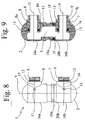
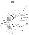
- a piping union 1 includes a main body 2, having a passage 3 for the fluid coming from such piping, equipped with at least an inlet 4 and at least an outlet 5.
- the union 1 further presents at least an inlet tubular body 7 and at least an outlet tubular body 8, respectively associable with the inlet 4 and the outlet 5 of the passage 3 of the main body 2.
- Such inlet and outlet tubular bodies 7, 8 are inserted in the main body 2 as a fitting, in particular in such a way that the main axis 6 of the main body 2 is perpendicular to the main axes 14, 15 of the two tubular bodies 7, 8.
- the main axes 14, 15 of the two tubular bodies 7, 8, when inserted in the main body 2, are in turn parallel therebetween.
- the portion 7a, 8a of the tubular bodies 7, 8 which contacts the main body 2 is advantageously equipped with first sealing gaskets 13, for example O-rings, for improving the fastening between the different bodies 2, 7, 8 and avoiding any water leakages in the environment to be heated, which would also lead to a faster wear of the union 1 itself.
- first sealing gaskets 13 for example O-rings
- fastening means 10 are generally represented by grub screws which are screwed, preferably using an Allen wrench, in proper through-seats 11 having a thread 12, obtained in the main body 2 for carrying out a pusher action on the tubular bodies 7, 8.
- this kind of mounting allows to disconnect at any time the tubular bodies 7, 8 from the main body 2 for performing maintenance operations, such as the replacement of the first sealing gaskets 13 or for changing the configuration of the radiating element itself.
- the number of tubular bodies 7, 8 which can be inserted in the main body 2, and therefore the total number of inlets 4 and outlets 5 of the passage 3 of the main body 2 is equal to the number of horizontal manifolds included in the radiating element on which the union is to be carried out.
- the tubular bodies 7, 8 are directly associable to the manifolds of the radiating elements.
- the fluid falls through the vertical tubes of the radiating element towards the second lower manifold where, through the second fitting 1 reaches the first lower manifold, which also collects the fluid falling from the vertical tubes connected with the first upper manifold and, after having cross it, returns in the plumbing.
- a radiating element with three horizontal manifolds is equipped with a first fitting 1 associated with the upper manifolds having an inlet 4 and two outlets 5 and a second fitting 1 mounted on the lower manifolds having two inlets 4 and an outlet 5.
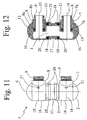
- the main body 2 is formed by at least two secondary bodies 16 associable therebetween, each containing the inlet 4 or the outlet 5 of the fluid passage 3.
- the union 1 can be mounted on any radiating element independently of the existing distance between the parallel horizontal manifolds. Such distance, in fact, is not conventionally fixed, as the radiating elements of this type have a reduced market share and as they can also be formed by two or more radiating elements welded together.
- a piping union 1 according to the device in the second embodiment consists of two or more secondary bodies 16 telescopically associable for adjusting the distance between the inlet and outlet tubular bodies 7, 8.
- the secondary bodies 16 are associated as fitting. Therefore, for example, when the main body 2 of the union 1 consists of two secondary bodies 16a, 16b, a first secondary body 16a is equipped with an end portion 19a of a smaller diameter with respect to the diameter of a second secondary body 16b, so as to allow such end portion 19a to be inserted in a seat 20b foreseen in this second secondary body 16b.
- this end portion 19a suitable for being inserted within the second secondary body 16b is equipped with second sealing gaskets 18, for example O-rings, for preventing leakages of fluid from the passage 3.
- the coupling between the secondary bodies 16a, 16b is structured so as to allow a following disassembling which permits, for example, to carry out maintenance operations.
- the number of secondary bodies 16 is equal to the number of tubular bodies 7, 8 and the number of horizontal manifolds of the radiating element on which it is mounted.
- the inlet and outlet tubular bodies 7, 8 are screwed to the manifolds of a radiating element, then the main body 2 is formed by mounting the secondary bodies 16 which composes it and by adjusting the distance based on the distance of the manifolds of the radiating element and, finally, one proceeds to the mounting of the main body 2 on the tubular bodies 7, 8 by further adjusting the fastening between the secondary bodies 16, if necessary.
- the union 1 further includes at least a connecting body 17, through which the two or more secondary bodies 16 are mutually associable.
- each secondary body 16 results telescopically connected to a connecting body 17 always for adapting the union 1 to any distance between the manifolds of the radiating element.
- each secondary body 16 is equipped with a seat 20 in at least an end portion 21 thereof, in which the connecting body 17 is fitted for forming the structure of the main body 2.
- second sealing gaskets 18 for example O-rings
- the union 1 After the mounting on the radiating element, the union 1 can be disassembled for performing maintenance operations.
- a main body 2 includes a number of secondary bodies 16 equal to the number of horizontal manifolds of the radiating element on which it is mounted and a number of connecting bodies 17 equal to the number of secondary bodies 16 less one.
- the assembly of this kind of unions 1 follows the preceding one. Indeed, after having screwed the tubular bodies 7, 8 to the manifolds of the radiating element, the main body 2 is carried out by mounting the secondary bodies 16 on the connecting bodies 17 and adjusting the distance thereof. Subsequently, such main body 2 is fixed as a joint on the tubular bodies 7, 8, preferably by also using the fastening means 10 and the adjustment previously carried out on the telescopic mechanism is improved.
- the invention attains important advantages.
- the union above described is utilizable with all the heating plants commonly carried out and can be directly mounted on the radiating elements without the need of further processings, which would negatively weigh on the costs.
- the possibility of a telescopic adjustment of the main body length allows to adapt the union to any kind of radiating element having more than one horizontal manifold.
- a further advantage is that the union of the invention easily allows to join together more than two manifolds and therefore it can be also used on radiating elements of large dimensions.
- the couplings between the different components of the union are reversible so as to make easier the maintenance operations, for example.
- the union shown by the invention is also advantageous because it has a pleasant impact on the aesthetic of the radiating element.
- a radiating element equipped with the shown union has the same operation principle than a conventional radiating element and therefore, for example, the temperature of the room to be heated can easily be adjusted by a thermostatic valve placed on the connection between the discharge piping of the plant and the radiating element.
Landscapes
- Engineering & Computer Science (AREA)
- General Engineering & Computer Science (AREA)
- Mechanical Engineering (AREA)
- Physics & Mathematics (AREA)
- Thermal Sciences (AREA)
- Chemical & Material Sciences (AREA)
- Combustion & Propulsion (AREA)
- Branch Pipes, Bends, And The Like (AREA)
- Quick-Acting Or Multi-Walled Pipe Joints (AREA)
Claims (15)
- Rohrverbindung (1), umfassend einen Hauptkörper (2), aufweisend einen Durchgang (3) für ein Fluid, ausgestattet mit mindestens einem Einlass (4) und mindestens einem Auslass (5), und mindestens einen Einlassrohrkörper (7), betriebswirksam assoziierbar mit dem Einlass (4) des Hauptkörpers (2), und mindestens einen Auslassrohrkörper (8), betriebswirksam assoziierbar mit dem Auslass (5) des Hauptkörpers (2), wobei der Einlassrohrkörper (7) und der Auslassrohrkörper (8) betriebswirksam mit Rohrleitungen assoziierbar sind, wobei der Hauptkörper (2) mindestens zwei Hilfskörper (16) umfasst, die jeweils den Einlass (4) bzw. den Auslass (5) enthalten, und mindestens einen Verbindungskörper (17), wobei die zwei Hilfskörper (16) gegenseitig durch den Verbindungskörper (17) assoziierbar und auf teleskopische Weise bewegbar mit dem Verbindungskörper (17) assoziierbar sind, um den Abstand zwischen dem Einlassrohrkörper (7) und dem Auslassrohrkörper (8) zu justieren, und wobei der Einlassrohrkörper (7) und der Auslassrohrkörper (8) jeweils als Fitting mit dem Einlass (4) und dem Auslass (5) des Hauptkörpers (2) assoziierbar sind, dadurch gekennzeichnet, dass die Rohrverbindung (1) zudem Befestigungsmittel (10) umfasst, die mit dem Einlassrohrkörper (7) und dem Auslassrohrkörper (8) durch Durchgangssitze (11), ausgebildet im Hauptkörper (2), in Eingriff gelangen können, um die Befestigung zwischen dem Hauptkörper (2) und dem Einlass- und dem Auslassrohrkörper (7, 8) zu gewährleisten.
- Rohrverbindung (1) nach dem vorhergehenden Anspruch, dadurch gekennzeichnet, dass der Einlassrohrkörper (7) und der Auslassrohrkörper (8) mittels eines Gewindes (9) mit den Rohrleitungen verschraubt werden können.
- Rohrverbindung (1) nach einem der vorhergehenden Ansprüche, dadurch gekennzeichnet, dass der Einlassrohrkörper (7) und der Auslassrohrkörper (8) mit ersten Dichtungspackungen (13) versehen sind, platziert an einem Abschnitt (7a, 8a), assoziierbar mit dem Hauptkörper (2), und an einem Abschnitt (7b, 8b), assoziierbar mit den Rohrleitungen.
- Rohrverbindung (1) nach einem der Ansprüche 1 bis 3, dadurch gekennzeichnet, dass es sich bei den Befestigungsmitteln (10) um Gewindestifte handelt, die in einem Gewinde (12) der Durchgangssitze (11), die am Hauptkörper (2) ausgebildet sind, eingeschraubt werden können.
- Rohrverbindung (1) nach einem der vorhergehenden Ansprüche, dadurch gekennzeichnet, dass der Einlassrohrkörper (7) und der Auslassrohrkörper (8) mit dem Hauptkörper (2) assoziierbar sind, sodass eine Hauptachse (6) des Hauptkörpers (2) rechtwinklig zu einer Hauptachse (14) des Einlassrohrkörpers (7) und zu einer Hauptachse (15) des Auslassrohrkörpers (8) verläuft.
- Rohrverbindung (1) nach einem der vorhergehenden Ansprüche, dadurch gekennzeichnet, dass der Einlassrohrkörper (7) und der Auslassrohrkörper (8) mit dem Hauptkörper (2) assoziierbar sind, sodass die Hauptachse (14) des Einlassrohrkörpers (7) parallel zur Hauptachse (15) des Auslassrohrkörpers (8) verläuft.
- Rohrverbindung (1) nach einem der vorhergehenden Ansprüche, wobei ein jeder Hilfskörper (16) mit einem Sitz (20) an mindestens einem Endabschnitt (21) davon ausgestattet ist, in den der Verbindungskörper (17) eingepasst wird, um die Struktur des Hauptkörpers (2) zu bilden.
- Rohrverbindung (1) nach einem der vorhergehenden Ansprüche, dadurch gekennzeichnet, dass sie zudem zweite Dichtungspackungen (18) umfasst, um die Kupplung zwischen den Hilfskörpern (16) und dem Verbindungskörper (17) zu fixieren und Leckagen des Fluids aus dem Durchgang (3) zu vermeiden.
- Rohrverbindung (1) nach Anspruch 8, dadurch gekennzeichnet, dass die zweiten Dichtungspackungen (18) an Abschnitten des Verbindungskörpers (17) platziert sind, die in die Hilfskörper (16) eingefügt sind.
- Rohrverbindung (1) nach einem der vorhergehenden Ansprüche, dadurch gekennzeichnet, dass sie drei der Rohrkörper (7, 8) und drei der Hilfskörper (16) umfasst, wobei die drei Hilfskörper (16) bewegbar untereinander assoziiert sind und ein jeder mit den drei Rohrkörpern (7, 8) assoziierbar ist.
- Rohrverbindung (1) nach Anspruch 10, dadurch gekennzeichnet, dass die drei Hilfskörper (16) teleskopisch untereinander assoziiert sind.
- Fluiddynamische Anlage, dadurch gekennzeichnet, dass sie eine Rohrverbindung (1) nach einem der vorhergehenden Ansprüche umfasst.
- Strahlelement, aufweisend mindestens zwei Verteilerrohre, verbunden mittels der Rohrverbindung nach einem der Ansprüche 1 bis 11, wobei der Einlassrohrkörper (7) und der Auslassrohrkörper (8) mit den Verteilerrohren assoziiert sind.
- Strahlelement nach Anspruch 13, aufweisend in einem oberen Teil die zwei Verteilerrohre, verbunden mittels einer Rohrverbindung nach einem der Ansprüche 1 bis 11, und in einem unteren Teil zwei weitere Verteilerrohre, verbunden mittels einer weiteren Rohrverbindung nach einem der Ansprüche 1 bis 11, sowie vertikale Rohre, die eines der oberen Verteilerrohre mit einem der unteren Verteilerrohre und das andere der oberen Verteilerrohre mit dem anderen der unteren Verteilerrohre verbinden.
- Verfahren zur Montage der Rohrverbindung (1) nach einem der Ansprüche 1 bis 11, wobei der Hauptkörper (2) nach dem Anschrauben des Einlass- und des Auslasskörpers (7, 8) an Verteilerrohren eines Strahlelements ausgeführt wird, indem die Hilfskörper (16) am Verbindungskörper (17) montiert und dessen Abstand justiert wird, wobei der Hauptkörper (2) anschließend als Fitting am Einlass- und am Auslasskörper (7, 8) auch durch Nutzung der Befestigungsmittel (10) fixiert wird und die zuvor am Teleskopmechanismus durchgeführte Justierung verbessert wird.
Applications Claiming Priority (1)
| Application Number | Priority Date | Filing Date | Title |
|---|---|---|---|
| ITBS20050025 ITBS20050025A1 (it) | 2005-02-28 | 2005-02-28 | Raccordo per tubazioni |
Publications (3)
| Publication Number | Publication Date |
|---|---|
| EP1710509A2 EP1710509A2 (de) | 2006-10-11 |
| EP1710509A3 EP1710509A3 (de) | 2007-02-14 |
| EP1710509B1 true EP1710509B1 (de) | 2016-02-03 |
Family
ID=36484415
Family Applications (1)
| Application Number | Title | Priority Date | Filing Date |
|---|---|---|---|
| EP06110375.0A Expired - Lifetime EP1710509B1 (de) | 2005-02-28 | 2006-02-24 | Rohrverbindung |
Country Status (2)
| Country | Link |
|---|---|
| EP (1) | EP1710509B1 (de) |
| IT (1) | ITBS20050025A1 (de) |
Family Cites Families (9)
| Publication number | Priority date | Publication date | Assignee | Title |
|---|---|---|---|---|
| US2486141A (en) * | 1946-10-10 | 1949-10-25 | Mel Products Company | Diversion fitting for hot-water heating systems |
| IT8021903V0 (it) * | 1980-05-26 | 1980-05-26 | Giacomini Rubinetterie | Collettore per la distribuzione di fluidi, per esempio dell'acqua calda, in impianti di riscaldamento. |
| DE19711074A1 (de) * | 1997-03-18 | 1998-09-24 | Simplex Wilfer Gmbh & Co | Vorrichtung zum Anschluß eines Heizkörpers |
| DE29723433U1 (de) * | 1997-05-16 | 1998-09-17 | Honeywell Ag, 63067 Offenbach | 3-Wege-Mischer |
| US6447028B1 (en) * | 2000-08-18 | 2002-09-10 | Asco Controls, L.P. | Joint fitting |
| FR2815110B1 (fr) * | 2000-10-11 | 2006-02-17 | Renard Gerard | Ensemble de deux conduits de gaz chauds raccordes au moyen d'un coupleur, procede de raccordement et coupleur correspondant |
| US20040046385A1 (en) * | 2002-09-05 | 2004-03-11 | Sami Shemtov | Low profile junction box connector |
| WO2004090429A1 (en) * | 2003-04-10 | 2004-10-21 | Bozzi, Alejandro | Hydraulic joint articulated device and use thereof with a heat radiator |
| US6957831B1 (en) * | 2003-12-17 | 2005-10-25 | Giant Factories Inc. | Nipple for hot water tank conduits |
-
2005
- 2005-02-28 IT ITBS20050025 patent/ITBS20050025A1/it unknown
-
2006
- 2006-02-24 EP EP06110375.0A patent/EP1710509B1/de not_active Expired - Lifetime
Also Published As
| Publication number | Publication date |
|---|---|
| ITBS20050025A1 (it) | 2006-09-01 |
| EP1710509A3 (de) | 2007-02-14 |
| EP1710509A2 (de) | 2006-10-11 |
Similar Documents
| Publication | Publication Date | Title |
|---|---|---|
| KR20100019511A (ko) | 워터 매니폴드 시스템 및 방법 | |
| EP0351155B1 (de) | Erweiterbarer Verteiler für ein Wasserversorgungssystem | |
| CN1746570B (zh) | 循环加热供暖系统的整体设备及供热方法 | |
| EP1859193A2 (de) | Verteiler für flüssigkeiten | |
| US5950575A (en) | Hydronic manifold | |
| EP4108996A1 (de) | Modulare wärmestation | |
| US6712027B2 (en) | Hot water heating system and connector for use therewith | |
| EP2681494B1 (de) | Adaptervorrichtung zum anschluss eines heizkörperelements an ein installationssystem | |
| US6546898B1 (en) | Hydronic heating system and kit | |
| US6935361B2 (en) | Pipe, piping system, radiant heating system, and kit | |
| EP4108998B1 (de) | Monolithische heizstation mit bypass | |
| EP0614061B1 (de) | Steuereinrichtung für Plattenwärmetauscher und entsprechender Wärmetauscher | |
| EP0693658A1 (de) | Verbesserte Ventilanordnung für Anlagen, die sowohl für Heizungs- als auch für Haushaltsheisswasser vorgesehen ist | |
| CN212058396U (zh) | 一种微通道换热器 | |
| EP1710509A2 (de) | Rohrverbindung | |
| EP1065447A2 (de) | Verteiler für thermisches System mit Zwangsumlauf | |
| EP1944554A2 (de) | Einheit und Verfahren zur Verteilung von Flüssigkeiten | |
| US20030015326A1 (en) | Water distribution network for domestic water and fire protection application | |
| EP4108997A1 (de) | Verbindungsvorrichtung für eine wärmestation | |
| CN104482581A (zh) | 一种毛细管网与分集水器的连接装置及连接方法 | |
| EP0387569A1 (de) | Einteiliges siebenwegiges Rohrformstück für den Anschluss von Wasserrohren | |
| RU2272224C2 (ru) | Отопительный конвектор | |
| WO2015136501A1 (en) | Connection device for connecting a heating radiator to a plumbing system | |
| EP0675312A1 (de) | Doppelverteiler für Warmwasserheizanlagen eines standardisierten Typs | |
| RU2408824C2 (ru) | Отопительный конвектор и способ монтажа его теплового термостатического регулятора расхода теплоносителя |
Legal Events
| Date | Code | Title | Description |
|---|---|---|---|
| PUAI | Public reference made under article 153(3) epc to a published international application that has entered the european phase |
Free format text: ORIGINAL CODE: 0009012 |
|
| AK | Designated contracting states |
Kind code of ref document: A2 Designated state(s): AT BE BG CH CY CZ DE DK EE ES FI FR GB GR HU IE IS IT LI LT LU LV MC NL PL PT RO SE SI SK TR |
|
| AX | Request for extension of the european patent |
Extension state: AL BA HR MK YU |
|
| PUAL | Search report despatched |
Free format text: ORIGINAL CODE: 0009013 |
|
| AK | Designated contracting states |
Kind code of ref document: A3 Designated state(s): AT BE BG CH CY CZ DE DK EE ES FI FR GB GR HU IE IS IT LI LT LU LV MC NL PL PT RO SE SI SK TR |
|
| AX | Request for extension of the european patent |
Extension state: AL BA HR MK YU |
|
| RIC1 | Information provided on ipc code assigned before grant |
Ipc: F24H 9/12 20060101ALI20070109BHEP Ipc: F16L 41/08 20060101ALI20070109BHEP Ipc: F24D 3/10 20060101AFI20060901BHEP Ipc: F16L 41/10 20060101ALI20070109BHEP |
|
| 17P | Request for examination filed |
Effective date: 20070621 |
|
| AKX | Designation fees paid |
Designated state(s): AT BE BG CH CY CZ DE DK EE ES FI FR GB GR HU IE IS IT LI LT LU LV MC NL PL PT RO SE SI SK TR |
|
| 17Q | First examination report despatched |
Effective date: 20130429 |
|
| REG | Reference to a national code |
Ref country code: DE Ref legal event code: R079 Ref document number: 602006047867 Country of ref document: DE Free format text: PREVIOUS MAIN CLASS: F24D0003100000 Ipc: F16L0041020000 |
|
| RIC1 | Information provided on ipc code assigned before grant |
Ipc: F16L 41/02 20060101AFI20150518BHEP Ipc: F28F 9/26 20060101ALI20150518BHEP Ipc: F16L 41/14 20060101ALI20150518BHEP Ipc: F24D 19/00 20060101ALI20150518BHEP |
|
| GRAP | Despatch of communication of intention to grant a patent |
Free format text: ORIGINAL CODE: EPIDOSNIGR1 |
|
| INTG | Intention to grant announced |
Effective date: 20150709 |
|
| RAP1 | Party data changed (applicant data changed or rights of an application transferred) |
Owner name: CO.GE.FIN. S.R.L. |
|
| GRAS | Grant fee paid |
Free format text: ORIGINAL CODE: EPIDOSNIGR3 |
|
| GRAA | (expected) grant |
Free format text: ORIGINAL CODE: 0009210 |
|
| INTG | Intention to grant announced |
Effective date: 20151130 |
|
| AK | Designated contracting states |
Kind code of ref document: B1 Designated state(s): AT BE BG CH CY CZ DE DK EE ES FI FR GB GR HU IE IS IT LI LT LU LV MC NL PL PT RO SE SI SK TR |
|
| REG | Reference to a national code |
Ref country code: GB Ref legal event code: FG4D |
|
| REG | Reference to a national code |
Ref country code: AT Ref legal event code: REF Ref document number: 773859 Country of ref document: AT Kind code of ref document: T Effective date: 20160215 Ref country code: CH Ref legal event code: EP |
|
| REG | Reference to a national code |
Ref country code: IE Ref legal event code: FG4D |
|
| REG | Reference to a national code |
Ref country code: FR Ref legal event code: PLFP Year of fee payment: 11 |
|
| REG | Reference to a national code |
Ref country code: DE Ref legal event code: R096 Ref document number: 602006047867 Country of ref document: DE |
|
| PGFP | Annual fee paid to national office [announced via postgrant information from national office to epo] |
Ref country code: GB Payment date: 20160226 Year of fee payment: 11 Ref country code: FR Payment date: 20160229 Year of fee payment: 11 |
|
| REG | Reference to a national code |
Ref country code: LT Ref legal event code: MG4D Ref country code: NL Ref legal event code: MP Effective date: 20160203 |
|
| REG | Reference to a national code |
Ref country code: AT Ref legal event code: MK05 Ref document number: 773859 Country of ref document: AT Kind code of ref document: T Effective date: 20160203 |
|
| PG25 | Lapsed in a contracting state [announced via postgrant information from national office to epo] |
Ref country code: GR Free format text: LAPSE BECAUSE OF FAILURE TO SUBMIT A TRANSLATION OF THE DESCRIPTION OR TO PAY THE FEE WITHIN THE PRESCRIBED TIME-LIMIT Effective date: 20160504 Ref country code: IT Free format text: LAPSE BECAUSE OF FAILURE TO SUBMIT A TRANSLATION OF THE DESCRIPTION OR TO PAY THE FEE WITHIN THE PRESCRIBED TIME-LIMIT Effective date: 20160203 Ref country code: FI Free format text: LAPSE BECAUSE OF FAILURE TO SUBMIT A TRANSLATION OF THE DESCRIPTION OR TO PAY THE FEE WITHIN THE PRESCRIBED TIME-LIMIT Effective date: 20160203 Ref country code: ES Free format text: LAPSE BECAUSE OF FAILURE TO SUBMIT A TRANSLATION OF THE DESCRIPTION OR TO PAY THE FEE WITHIN THE PRESCRIBED TIME-LIMIT Effective date: 20160203 |
|
| PGFP | Annual fee paid to national office [announced via postgrant information from national office to epo] |
Ref country code: DE Payment date: 20160502 Year of fee payment: 11 |
|
| PG25 | Lapsed in a contracting state [announced via postgrant information from national office to epo] |
Ref country code: LV Free format text: LAPSE BECAUSE OF FAILURE TO SUBMIT A TRANSLATION OF THE DESCRIPTION OR TO PAY THE FEE WITHIN THE PRESCRIBED TIME-LIMIT Effective date: 20160203 Ref country code: AT Free format text: LAPSE BECAUSE OF FAILURE TO SUBMIT A TRANSLATION OF THE DESCRIPTION OR TO PAY THE FEE WITHIN THE PRESCRIBED TIME-LIMIT Effective date: 20160203 Ref country code: LT Free format text: LAPSE BECAUSE OF FAILURE TO SUBMIT A TRANSLATION OF THE DESCRIPTION OR TO PAY THE FEE WITHIN THE PRESCRIBED TIME-LIMIT Effective date: 20160203 Ref country code: PT Free format text: LAPSE BECAUSE OF FAILURE TO SUBMIT A TRANSLATION OF THE DESCRIPTION OR TO PAY THE FEE WITHIN THE PRESCRIBED TIME-LIMIT Effective date: 20160603 Ref country code: PL Free format text: LAPSE BECAUSE OF FAILURE TO SUBMIT A TRANSLATION OF THE DESCRIPTION OR TO PAY THE FEE WITHIN THE PRESCRIBED TIME-LIMIT Effective date: 20160203 Ref country code: SE Free format text: LAPSE BECAUSE OF FAILURE TO SUBMIT A TRANSLATION OF THE DESCRIPTION OR TO PAY THE FEE WITHIN THE PRESCRIBED TIME-LIMIT Effective date: 20160203 Ref country code: IS Free format text: LAPSE BECAUSE OF FAILURE TO SUBMIT A TRANSLATION OF THE DESCRIPTION OR TO PAY THE FEE WITHIN THE PRESCRIBED TIME-LIMIT Effective date: 20160603 Ref country code: BE Free format text: LAPSE BECAUSE OF NON-PAYMENT OF DUE FEES Effective date: 20160229 Ref country code: NL Free format text: LAPSE BECAUSE OF FAILURE TO SUBMIT A TRANSLATION OF THE DESCRIPTION OR TO PAY THE FEE WITHIN THE PRESCRIBED TIME-LIMIT Effective date: 20160203 |
|
| REG | Reference to a national code |
Ref country code: CH Ref legal event code: PL |
|
| PG25 | Lapsed in a contracting state [announced via postgrant information from national office to epo] |
Ref country code: DK Free format text: LAPSE BECAUSE OF FAILURE TO SUBMIT A TRANSLATION OF THE DESCRIPTION OR TO PAY THE FEE WITHIN THE PRESCRIBED TIME-LIMIT Effective date: 20160203 Ref country code: CH Free format text: LAPSE BECAUSE OF NON-PAYMENT OF DUE FEES Effective date: 20160229 Ref country code: EE Free format text: LAPSE BECAUSE OF FAILURE TO SUBMIT A TRANSLATION OF THE DESCRIPTION OR TO PAY THE FEE WITHIN THE PRESCRIBED TIME-LIMIT Effective date: 20160203 Ref country code: LI Free format text: LAPSE BECAUSE OF NON-PAYMENT OF DUE FEES Effective date: 20160229 |
|
| REG | Reference to a national code |
Ref country code: DE Ref legal event code: R097 Ref document number: 602006047867 Country of ref document: DE |
|
| PG25 | Lapsed in a contracting state [announced via postgrant information from national office to epo] |
Ref country code: SK Free format text: LAPSE BECAUSE OF FAILURE TO SUBMIT A TRANSLATION OF THE DESCRIPTION OR TO PAY THE FEE WITHIN THE PRESCRIBED TIME-LIMIT Effective date: 20160203 Ref country code: CZ Free format text: LAPSE BECAUSE OF FAILURE TO SUBMIT A TRANSLATION OF THE DESCRIPTION OR TO PAY THE FEE WITHIN THE PRESCRIBED TIME-LIMIT Effective date: 20160203 Ref country code: RO Free format text: LAPSE BECAUSE OF FAILURE TO SUBMIT A TRANSLATION OF THE DESCRIPTION OR TO PAY THE FEE WITHIN THE PRESCRIBED TIME-LIMIT Effective date: 20160203 |
|
| REG | Reference to a national code |
Ref country code: IE Ref legal event code: MM4A |
|
| PLBE | No opposition filed within time limit |
Free format text: ORIGINAL CODE: 0009261 |
|
| STAA | Information on the status of an ep patent application or granted ep patent |
Free format text: STATUS: NO OPPOSITION FILED WITHIN TIME LIMIT |
|
| PG25 | Lapsed in a contracting state [announced via postgrant information from national office to epo] |
Ref country code: BE Free format text: LAPSE BECAUSE OF FAILURE TO SUBMIT A TRANSLATION OF THE DESCRIPTION OR TO PAY THE FEE WITHIN THE PRESCRIBED TIME-LIMIT Effective date: 20160203 |
|
| 26N | No opposition filed |
Effective date: 20161104 |
|
| PG25 | Lapsed in a contracting state [announced via postgrant information from national office to epo] |
Ref country code: IE Free format text: LAPSE BECAUSE OF NON-PAYMENT OF DUE FEES Effective date: 20160224 |
|
| PG25 | Lapsed in a contracting state [announced via postgrant information from national office to epo] |
Ref country code: SI Free format text: LAPSE BECAUSE OF FAILURE TO SUBMIT A TRANSLATION OF THE DESCRIPTION OR TO PAY THE FEE WITHIN THE PRESCRIBED TIME-LIMIT Effective date: 20160203 Ref country code: BG Free format text: LAPSE BECAUSE OF FAILURE TO SUBMIT A TRANSLATION OF THE DESCRIPTION OR TO PAY THE FEE WITHIN THE PRESCRIBED TIME-LIMIT Effective date: 20160503 |
|
| REG | Reference to a national code |
Ref country code: DE Ref legal event code: R119 Ref document number: 602006047867 Country of ref document: DE |
|
| GBPC | Gb: european patent ceased through non-payment of renewal fee |
Effective date: 20170224 |
|
| REG | Reference to a national code |
Ref country code: FR Ref legal event code: ST Effective date: 20171031 |
|
| PG25 | Lapsed in a contracting state [announced via postgrant information from national office to epo] |
Ref country code: DE Free format text: LAPSE BECAUSE OF NON-PAYMENT OF DUE FEES Effective date: 20170901 Ref country code: FR Free format text: LAPSE BECAUSE OF NON-PAYMENT OF DUE FEES Effective date: 20170228 |
|
| PG25 | Lapsed in a contracting state [announced via postgrant information from national office to epo] |
Ref country code: GB Free format text: LAPSE BECAUSE OF NON-PAYMENT OF DUE FEES Effective date: 20170224 |
|
| PG25 | Lapsed in a contracting state [announced via postgrant information from national office to epo] |
Ref country code: CY Free format text: LAPSE BECAUSE OF FAILURE TO SUBMIT A TRANSLATION OF THE DESCRIPTION OR TO PAY THE FEE WITHIN THE PRESCRIBED TIME-LIMIT Effective date: 20160203 Ref country code: HU Free format text: LAPSE BECAUSE OF FAILURE TO SUBMIT A TRANSLATION OF THE DESCRIPTION OR TO PAY THE FEE WITHIN THE PRESCRIBED TIME-LIMIT; INVALID AB INITIO Effective date: 20060224 |
|
| PG25 | Lapsed in a contracting state [announced via postgrant information from national office to epo] |
Ref country code: TR Free format text: LAPSE BECAUSE OF FAILURE TO SUBMIT A TRANSLATION OF THE DESCRIPTION OR TO PAY THE FEE WITHIN THE PRESCRIBED TIME-LIMIT Effective date: 20160203 Ref country code: MC Free format text: LAPSE BECAUSE OF FAILURE TO SUBMIT A TRANSLATION OF THE DESCRIPTION OR TO PAY THE FEE WITHIN THE PRESCRIBED TIME-LIMIT Effective date: 20160203 Ref country code: LU Free format text: LAPSE BECAUSE OF NON-PAYMENT OF DUE FEES Effective date: 20160224 |