EP1710519B1 - Schneeerzeugungsprozess und entsprechende Vorrichtung - Google Patents
Schneeerzeugungsprozess und entsprechende Vorrichtung Download PDFInfo
- Publication number
- EP1710519B1 EP1710519B1 EP06445012A EP06445012A EP1710519B1 EP 1710519 B1 EP1710519 B1 EP 1710519B1 EP 06445012 A EP06445012 A EP 06445012A EP 06445012 A EP06445012 A EP 06445012A EP 1710519 B1 EP1710519 B1 EP 1710519B1
- Authority
- EP
- European Patent Office
- Prior art keywords
- water
- nozzles
- bulk water
- bulk
- curtain
- Prior art date
- Legal status (The legal status is an assumption and is not a legal conclusion. Google has not performed a legal analysis and makes no representation as to the accuracy of the status listed.)
- Expired - Lifetime
Links
Images



Classifications
-
- B—PERFORMING OPERATIONS; TRANSPORTING
- B05—SPRAYING OR ATOMISING IN GENERAL; APPLYING FLUENT MATERIALS TO SURFACES, IN GENERAL
- B05B—SPRAYING APPARATUS; ATOMISING APPARATUS; NOZZLES
- B05B1/00—Nozzles, spray heads or other outlets, with or without auxiliary devices such as valves, heating means
- B05B1/34—Nozzles, spray heads or other outlets, with or without auxiliary devices such as valves, heating means designed to influence the nature of flow of the liquid or other fluent material, e.g. to produce swirl
- B05B1/3405—Nozzles, spray heads or other outlets, with or without auxiliary devices such as valves, heating means designed to influence the nature of flow of the liquid or other fluent material, e.g. to produce swirl to produce swirl
- B05B1/341—Nozzles, spray heads or other outlets, with or without auxiliary devices such as valves, heating means designed to influence the nature of flow of the liquid or other fluent material, e.g. to produce swirl to produce swirl before discharging the liquid or other fluent material, e.g. in a swirl chamber upstream the spray outlet
- B05B1/3421—Nozzles, spray heads or other outlets, with or without auxiliary devices such as valves, heating means designed to influence the nature of flow of the liquid or other fluent material, e.g. to produce swirl to produce swirl before discharging the liquid or other fluent material, e.g. in a swirl chamber upstream the spray outlet with channels emerging substantially tangentially in the swirl chamber
- B05B1/3431—Nozzles, spray heads or other outlets, with or without auxiliary devices such as valves, heating means designed to influence the nature of flow of the liquid or other fluent material, e.g. to produce swirl to produce swirl before discharging the liquid or other fluent material, e.g. in a swirl chamber upstream the spray outlet with channels emerging substantially tangentially in the swirl chamber the channels being formed at the interface of cooperating elements, e.g. by means of grooves
- B05B1/3442—Nozzles, spray heads or other outlets, with or without auxiliary devices such as valves, heating means designed to influence the nature of flow of the liquid or other fluent material, e.g. to produce swirl to produce swirl before discharging the liquid or other fluent material, e.g. in a swirl chamber upstream the spray outlet with channels emerging substantially tangentially in the swirl chamber the channels being formed at the interface of cooperating elements, e.g. by means of grooves the interface being a cone having the same axis as the outlet
-
- B—PERFORMING OPERATIONS; TRANSPORTING
- B05—SPRAYING OR ATOMISING IN GENERAL; APPLYING FLUENT MATERIALS TO SURFACES, IN GENERAL
- B05B—SPRAYING APPARATUS; ATOMISING APPARATUS; NOZZLES
- B05B7/00—Spraying apparatus for discharge of liquids or other fluent materials from two or more sources, e.g. of liquid and air, of powder and gas
- B05B7/02—Spray pistols; Apparatus for discharge
- B05B7/08—Spray pistols; Apparatus for discharge with separate outlet orifices, e.g. to form parallel jets, i.e. the axis of the jets being parallel, to form intersecting jets, i.e. the axis of the jets converging but not necessarily intersecting at a point
-
- B—PERFORMING OPERATIONS; TRANSPORTING
- B05—SPRAYING OR ATOMISING IN GENERAL; APPLYING FLUENT MATERIALS TO SURFACES, IN GENERAL
- B05B—SPRAYING APPARATUS; ATOMISING APPARATUS; NOZZLES
- B05B1/00—Nozzles, spray heads or other outlets, with or without auxiliary devices such as valves, heating means
- B05B1/14—Nozzles, spray heads or other outlets, with or without auxiliary devices such as valves, heating means with multiple outlet openings; with strainers in or outside the outlet opening
- B05B1/16—Nozzles, spray heads or other outlets, with or without auxiliary devices such as valves, heating means with multiple outlet openings; with strainers in or outside the outlet opening having selectively- effective outlets
-
- B—PERFORMING OPERATIONS; TRANSPORTING
- B05—SPRAYING OR ATOMISING IN GENERAL; APPLYING FLUENT MATERIALS TO SURFACES, IN GENERAL
- B05B—SPRAYING APPARATUS; ATOMISING APPARATUS; NOZZLES
- B05B7/00—Spraying apparatus for discharge of liquids or other fluent materials from two or more sources, e.g. of liquid and air, of powder and gas
- B05B7/02—Spray pistols; Apparatus for discharge
- B05B7/08—Spray pistols; Apparatus for discharge with separate outlet orifices, e.g. to form parallel jets, i.e. the axis of the jets being parallel, to form intersecting jets, i.e. the axis of the jets converging but not necessarily intersecting at a point
- B05B7/0807—Spray pistols; Apparatus for discharge with separate outlet orifices, e.g. to form parallel jets, i.e. the axis of the jets being parallel, to form intersecting jets, i.e. the axis of the jets converging but not necessarily intersecting at a point to form intersecting jets
- B05B7/0815—Spray pistols; Apparatus for discharge with separate outlet orifices, e.g. to form parallel jets, i.e. the axis of the jets being parallel, to form intersecting jets, i.e. the axis of the jets converging but not necessarily intersecting at a point to form intersecting jets with at least one gas jet intersecting a jet constituted by a liquid or a mixture containing a liquid for controlling the shape of the latter
-
- B—PERFORMING OPERATIONS; TRANSPORTING
- B05—SPRAYING OR ATOMISING IN GENERAL; APPLYING FLUENT MATERIALS TO SURFACES, IN GENERAL
- B05B—SPRAYING APPARATUS; ATOMISING APPARATUS; NOZZLES
- B05B7/00—Spraying apparatus for discharge of liquids or other fluent materials from two or more sources, e.g. of liquid and air, of powder and gas
- B05B7/02—Spray pistols; Apparatus for discharge
- B05B7/08—Spray pistols; Apparatus for discharge with separate outlet orifices, e.g. to form parallel jets, i.e. the axis of the jets being parallel, to form intersecting jets, i.e. the axis of the jets converging but not necessarily intersecting at a point
- B05B7/0892—Spray pistols; Apparatus for discharge with separate outlet orifices, e.g. to form parallel jets, i.e. the axis of the jets being parallel, to form intersecting jets, i.e. the axis of the jets converging but not necessarily intersecting at a point the outlet orifices for jets constituted by a liquid or a mixture containing a liquid being disposed on a circle
-
- F—MECHANICAL ENGINEERING; LIGHTING; HEATING; WEAPONS; BLASTING
- F25—REFRIGERATION OR COOLING; COMBINED HEATING AND REFRIGERATION SYSTEMS; HEAT PUMP SYSTEMS; MANUFACTURE OR STORAGE OF ICE; LIQUEFACTION SOLIDIFICATION OF GASES
- F25C—PRODUCING, WORKING OR HANDLING ICE
- F25C3/00—Processes or apparatus specially adapted for producing ice or snow for winter sports or similar recreational purposes, e.g. for sporting installations; Producing artificial snow
- F25C3/04—Processes or apparatus specially adapted for producing ice or snow for winter sports or similar recreational purposes, e.g. for sporting installations; Producing artificial snow for sledging or ski trails; Producing artificial snow
-
- F—MECHANICAL ENGINEERING; LIGHTING; HEATING; WEAPONS; BLASTING
- F25—REFRIGERATION OR COOLING; COMBINED HEATING AND REFRIGERATION SYSTEMS; HEAT PUMP SYSTEMS; MANUFACTURE OR STORAGE OF ICE; LIQUEFACTION SOLIDIFICATION OF GASES
- F25C—PRODUCING, WORKING OR HANDLING ICE
- F25C2303/00—Special arrangements or features for producing ice or snow for winter sports or similar recreational purposes, e.g. for sporting installations; Special arrangements or features for producing artificial snow
- F25C2303/048—Snow making by using means for spraying water
- F25C2303/0481—Snow making by using means for spraying water with the use of compressed air
Definitions
- the invention relates to a device for the making of artificial snow by bringing pressurized water and air to flow from a spraying device.
- Various kinds of such devices are previously known, e.g. in the form of so called snow canons, where a strong fan provides a central, strong air flow in which water jets are injected inwardly-forwardly, or so called “sticks" having air and water channels communicating with a spray assembly located high above the ground, wherein water flows out in a sprayed beam while forming small snow particles, under the influence of adjacent air streams, said snow particles growing into larger snow particles before falling onto the ground.
- the invention relates to a device of the latter kind, comprising a spray assembly located relatively high above the ground, e.g. 3-10 m.
- a problem with such devices is that a large amount of pressurized air is required, thus consuming a great deal of energy, in order to sufficiently atomize the water sprays by means of the transverse water sprays, so that a desired capacity is obtained.
- the snow making becomes rather costly since the associated compressors require a high power.
- the artificially made snow has a high content of water in each snow particle at temperatures close to 0°C and at high moisture content of the ambient air. In this way, the snow becomes heavy and icy and is not suitable for skiing or snow boarding.
- An object of the present invention is to reduce the required amount of energy when making snow by the method indicated above and to improve the snow quality by creating snow particles having a relatively low content of water and ice.
- the water is atomized into very small drops and are mixed with air, in the form of so called "nuclei", and not primarily by breaking the water jets by means of air streams.
- the central bulk water stream can hereby retain its flow energy to a large degree and be thrown further away from the spray assembly before it is transformed into snow particles by interaction with the nuclei.
- the flow velocity of the bulk water stream there is also created a static low pressure, which will cause the enclosing curtain of nuclei to be drawn inwardly towards the water in the bulk water stream.
- the water jets should be formed as a planar layer, preferably diverging from the centre of the nozzle in order to achieve the best possible interaction with the surrounding nuclei curtain.
- a large number of atomizing nozzles are provided in an outer ring, so that a curtain is obtained which is substantially continuous in the circumferential direction.
- a very good operation is obtained if the nozzles are oriented such that the planar water jets are mutually parallel, preferably in different horizontal planes.
- the planar water jets are mutually parallel, preferably in different horizontal planes.
- a uniform snow distribution is obtained and the aggregation of snow bumps or heaps is avoided.
- this arrangement operates very well against the wind.
- the device shown in figures 1 and 1a comprises a device 2, anchored to the ground 1 in a manner known per se adjacent to a region to be covered by snow, having a mast 3, alternatively denoted “rod” or “stick”, preferably extending obliquely upwards and being provided at the top with a spray assembly 4.
- the device 2 comprises various apparatus, including a pressurized water connection, which is coupled to a pump station for the supply of water under a relatively high pressure, normally 15-35 bar, and an air compressor for the supply of pressurized air at a lower pressure, normally about 5-7 bar, as well as an electric control circuitry for the device.
- FIG 1a there is shown schematically a central bulk water stream, which is directed forwardly along a main direction A (in parallel to the axis of the spray assembly), and an annularly surrounding curtain consisting of said mixture of pressurized air and very small water particles, so called sprouts or nuclei.
- the central bulk water stream diverges somewhat in the main direction A, but in an axial region R near the spray assembly, the curtain C, consisting of the nuclei and driven by the pressurized air, will enclose the central bulk water stream B.
- the curtain C has the shape of a cylindrical shell, which is substantially continuous circumferentially and which encloses the inner bulk water stream B, which diverges somewhat in the main direction A.
- the curtain C there is a large amount of small nuclei, which are created, in a manner known per se, by atomizing nozzles ( figure 6 ), so that a cloud consisting of a mixture of air particles and water particles will propagate in a direction in parallel to the main direction A.
- atomizing nozzles figure 6
- the water jets should be planar and preferably diverge as a fan.
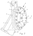
- the embodiment of the spray assembly shown in figures 2 and 3 consists essentially of an aluminium structure having a connection piece 5, comprising separate channels for water and pressurized air, a substantially circular, disc-like body 6 having an outer ring of atomizing nozzles 7 and a central head 8 with a number of water nozzles 9, 10 disposed in an annular arrangement.
- the central head 8 has a smaller diameter than the disc-like body 6.
- the atomizing nozzles 7 in the disc-like body 6 are connected to separate pressurized air and pressurized water channels, whereas the nozzles 9, 10 in the head 8 are connected to water channels only.
- On the drawing there are also shown a number of screws 11, by means of which the head 8 is fastened onto the disc-like body 6. The latter consists of number of different parts, which are mutually secured and mounted onto the connection piece 5.
- the spray assembly also includes four further water nozzles 12, disposed radially outwardly of the annularly arranged atomizing nozzles 7.
- the remaining four water nozzles 10 are arranged on the substantially cylindrical outer part of the head 8 and are obliquely directed in such a way that they are forwardly directed at an angle of about 60° relative to the axis A.
- the atomizing nozzles 7 in the disc-like body 6 are uniformly distributed in a circular ring, radially outside the head 8, and are all directed essentially in parallel to the axis A.
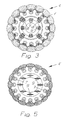
- the atomising nozzles 7 are of a larger number that the water nozzles 9, 10, namely 16 in the shown embodiment. See also the schematic view in fig. 3 , seen from the front on the axis A. In this view, the outer water nozzles 12 are not drawn.
- the water nozzles 9, 10 are directed in such a way with their elongated, slit-like orifices 91 ( figure 7 ) that these slit-like orifices are oriented substantially tangentially along the circumference relative to the axis A.
- the planar, diverging water jets from the water nozzles 9 and 10 will likewise be oriented with their planes oriented tangentially relative to imaginary circles extending through each ring of water nozzles.
- the nozzles 9 will thus form an inner ring, whereas the nozzles 10 form a second ring at a somewhat larger distance from the axis A.
- the central bulk water stream from the water nozzles 9, 10 will diverge forwardly along the axis A (see fig. 1 ), so that the surrounding, essentially cylindrical curtain C with nuclei or small snow particles will reach and, partially through suction, merge with the bulk water stream somewhat outside the region R.
- a second, modified embodiment of the spray assembly is schematically shown in figures 4 and 5 , wherein the main difference is that the bulk water nozzles 9' are disposed in one single, inner ring with the slit-like outlet orifices being oriented in mutually parallel planes.
- the planar water beams will flow in five mutually parallel planes.
- these planes are all horizontal, and such an arrangement has turned out to be especially advantageous by providing a very uniform distribution of the snow material on the ground, without any heaps in the form of bumps or humps, and this embodiment will operate very well even against the wind in that the mutually parallel flow layers are kept together even far away from the spray assembly.
- nozzles 7 As atomizing nozzles 7 one should preferably use nozzles of the kind disclosed in the published international patent application WO 9701392 .
- the pressurized air is led through a central, axial channel 71, whereas pressurized water is supplied via a cylindrical chamber inside the outer cylindrical wall 73 of the nozzle and via helical channels 74 into a whirl chamber 75 having a central, axial outlet orifice 76.
- a mixture of air and very small water particles flows outwardly as a diverging cone, so as to generate the above-mentioned sprouts or nuclei.
- the latter will expand substantially while flowing through the outlet orifice 76 and be transformed into very small snow particles, provided of course that the ambient temperature permits this.
- the atomizing nozzles as shown in fig. 6 , have been used previously in connection with snow making, namely in so called snow canons.
- snow canons operate quite differently than the present device.
- a snow canon has a strong fan which generates an air stream flowing through a cylindrical tube having a funnel-like opening. In this opening, there are a number of nozzle rings, which inject water beams into the air stream.
- a nozzle ring located closest to the opening are provided with the atomizing nozzles according to fig. 6 , and the flow conditions are substantially different from those of the device according to the present invention.
- the diverging bulk water stream and the cylindrical, surrounding curtain with nuclei are maintained a relatively long distance axially from the spray assembly. It has also turned out that the cylindrical curtain with nuclei will be sucked radially inwardly towards the central bulk water stream, which can be explained by the fact that the latter has an axial main flow direction which, due to the axial flow, will provide a static lower pressure. Hereby, the curtain with its nuclei will merge very well with the central bulk water stream and generate good conditions for a rapid growth of the snow particles.
- the outer water nozzles 12 ( figures 2 and 4 ), and it has turned out that these water jets will also be sucked in towards the nuclei curtain and merge with the rest of the stream, so that these water jets from the nozzles 12 will also generate snow particles.
- a first step only the atomizing nozzles 7 and the water nozzles 9 and 10 (and 9' respectively) are activated, whereupon, in a subsequent second step or in several subsequent steps, the outer water nozzles are activated. This can be done in response to a sufficiently low air temperature and/or a sufficiently low relative humidity in the ambient air. Alternatively, it is of course possible to control the flow continuously.
- the number of atomising nozzles should be substantially higher than the number of bulk water nozzles, so that the surrounding curtain with nuclei will be substantially continuous circumferentially.
- the number of bulk water nozzles are about 6 to 12, preferably 7 to 10, in particular 8, and the number of atomizing nozzles should be 10 to 30, preferably 14 to 20, in particular 16.
- the rings with bulk water nozzles and atomizing nozzles may be configured in a different manner, for example in more elongated, preferably closed configurations, e.g. oval. However, it is essential that the atomizing nozzles surround the bulk water nozzles, so that the curtain with nuclei will surround the bulk water stream substantially all around circumferentially.
Landscapes
- Engineering & Computer Science (AREA)
- Physics & Mathematics (AREA)
- Mechanical Engineering (AREA)
- Thermal Sciences (AREA)
- General Engineering & Computer Science (AREA)
- Nozzles (AREA)
- Electrical Discharge Machining, Electrochemical Machining, And Combined Machining (AREA)
Claims (19)
- Verfahren zur Herstellung von künstlichem Schnee, indem unter Druck gesetztes Wasser und Luft dazu veranlasst werden, aus dicht angeordneten Düsen in einer Sprühanordnung (4; 4') zu fließen, welche relativ hoch über dem Boden, z.B. 3 bis 10 m, angeordnet ist, wobei das Wasser in einem zentralen Hauptwasserstrom (B) fließt, der im Wesentlichen durch den Wasserdruck entlang einer Hauptrichtung nach vorne verbreitet wird und unter der Einwirkung von radial umgebenden, im Wesentlichen parallel ausgerichteten Strahlen, die aus Luft bestehen, die mit sehr kleinen, "zerstäubten" Wassertropfen vermischt ist, so genannten Keimen oder Kernen, kleine Schneepartikel erzeugt, die zu größeren Schneepartikeln heranwachsen, ehe sie den Boden erreichen, wobei der Hauptwasserstrom (B) und die Luftstrahlen mit vermischten Wassertropfen dazu veranlasst werden, durch eine integrierte Sprühanordnung zu fließen, die zumindest einen radialen inneren Ring aus Wasserdüsen und einen äußeren radial umgebenden Ring aus 10 bis 30 Zerstäuberdüsen aufweist, um eine zentrale Gruppe von planaren Wasserstrahlen und einen umgebenden, umfangsmäßig im Wesentlichen durchgehend einschließenden Vorhang aus Kernen, die in den Zerstäuberdüsen erzeugt werden, zu erzeugen, dadurch gekennzeichnet, dass jede Düse eine Wirbelkammer mit einer zentralen, axialen Auslassöffnung umfasst, und [die Kerne], unmittelbar nachdem sie daraus heraus fließen, zu Schneepartikeln gefrieren und in einem Abstand stromabwärts der Sprühanordnung sich mit den planaren Wasserstrahlen vermischen und mit diesen zusammenwirken, woraufhin die Schneepartikel schnell zu größeren Schneepartikeln heranwachsen.
- Verfahren nach Anspruch 1, wobei das Vermischen der Kerne (C) mit dem Hauptwasserstrom (B) zu mindest teilweise dadurch erfolgt, dass die Kerne durch einen von den Wasserstrahlen erzeugten Unterdruck zum Hauptwasserstrom angesogen werden.
- Verfahren nach Anspruch 2, wobei der Hauptwasserstrom (B) und der umgebende Vorhang (C) entlang einer im Wesentlichen horizontalen Richtung (A) gelenkt werden.
- Verfahren nach einem der Ansprüche 1 bis 3, wobei mindestens einige der Wasserstrahlen im Verhältnis zur Hauptrichtung (A) schräg ausgerichtet sind, so dass der Hauptwasserstrom (B) divergiert.
- Verfahren nach einem der Ansprüche 1 bis 4, wobei radial auswärts von dem Vorhang (C) eine Anzahl von weiteren Wasserstrahlen dazu gebracht werden, in eine derartige Richtung zu fließen, dass diese weiteren Wasserstrahlen mit dem Rest des Flusses vermischt werden und somit eine weiteres Wachstum der Schneepartikel erreichen.
- Verfahren nach einem der Ansprüche 1 bis 5, wobei anfänglich der zentrale Hauptwasserstrom (B) mit einem ersten Versorgungsdruck aktiviert wird, z.B. mindestens 15 bar, und der Vorhang (C) mit einem zweiten geringeren Versorgungsdruck aktiviert wird, der weniger als die Hälfte des ersten Versorgungsdrucks beträgt, z.B. nicht mehr als 7 bar.
- Verfahren nach Anspruch 6, wobei nach der anfänglichen Aktivierung des Hauptwasserstroms (B) und des Vorhangs (C) weitere Wasserstrahlen radial außerhalb des Vorhangs in einem oder mehreren nachfolgenden Schritten aktiviert werden.
- Verfahren nach Anspruch 7, wobei der oder die nachfolgenden Schritte als Reaktion auf eine sinkende Temperatur und/oder Luftfeuchtigkeit aktiviert werden.
- Vorrichtung zur Herstellung von künstlichem Schnee, umfassend Druckquellen, um jeweils Wasser und Luft unter Druck zu setzen, eine Sprühanordnung (4; 4'), die an die Druckquellen anschließbar ist und mindestens zwei Gruppen von nebeneinander liegenden Düsen aufweist, um jeweils unter Druck gesetztes Wasser und Luft in einer Hauptrichtung (A) zu sprühen, und einen Haltearm (3), um die Sprühanordnung mindestens 3 m über dem umgebenden Boden zu halten, wobei die Sprühanordnung (4, 4') ein integriertes Gehäuse (4, 4') aufweist, das mindestens einen radial inneren Ring aus Hauptwasserdüsen (9, 10; 9'), die geeignet sind, eine zentrale Gruppe von planaren Wasserstrahlen auszusprühen, und mindestens einen äußeren, radial umgebenden Ring aus 10 bis 30 Zerstäuberdüsen, um eine zentrale Gruppe von planaren Wasserstrahlen und einen umgebenden, umfangsmäßig im Wesentlichen durchgehend einschließenden Vorhang aus Kernen, die in den Zerstäuberdüsen erzeugt werden, zu bilden, aufweist, dadurch gekennzeichnet, dass jede Düse eine Wirbelkammer mit einer zentralen, axialen Auslassöffnung umfasst, und [die Kerne], unmittelbar nachdem sie daraus heraus fließen, zu Schneepartikeln gefrieren und in einem Abstand stromabwärts der Sprühanordnung sich mit den planaren Wasserstrahlen vermischen und mit diesen zusammenwirken, woraufhin die Schneepartikel schnell zu größeren Schneepartikeln heranwachsen.
- Vorrichtung nach Anspruch 9, wobei die Hauptrichtung (A) im Wesentlichen horizontal ist.
- Vorrichtung nach Anspruch 10, wobei der innere Ring (9, 10; 9') im Wesentlichen kreisförmig ist.
- Vorrichtung nach Anspruch 11, wobei zumindest einige der Hauptwasserdüsen (9, 10) im Verhältnis zur Hauptrichtung (A) des Hauptwasserstroms (B) schräg gerichtet sind, so dass der Hauptwasserstrahl (B) divergiert.
- Vorrichtung nach Anspruch 12, wobei die Hauptwasserdüsen (9, 10) in zwei konzentrischen inneren Ringen angeordnet und im Verhältnis zur Hauptrichtung in verschiedenen Winkeln schräg ausgerichtet sind.
- Vorrichtung nach einem der Ansprüche 9 bis 13, wobei die Hauptwasserdüsen (9, 10; 9') geeignet sind, um Wasserstrahlen zu erzeugen, die in einer oder mehreren Ebenen, die zueinander parallel und bevorzugt im Wesentlichen horizontal sind, planar sind.
- Vorrichtung nach einem der Ansprüche 9 bis 14, wobei die Hauptwasser- und Zerstäuberdüsen (7, 9, 10; 7, 9') derart liegen und angeordnet sind, dass der einschließende Vorhang (C) aus Kernen durch einen Unterdruck, der durch den Wasserfluss erzeugt wird, mindestens teilweise in den zentralen Hauptwasserstrom (B) gesogen wird.
- Vorrichtung nach Anspruch 9, dadurch gekennzeichnet, dass die Anzahl der Zerstäuberdüsen (7) größer ist als die Anzahl der Hauptwasserdüsen (9, 10; 9').
- Vorrichtung nach Anspruch 16, wobei die Anzahl der Hauptwasserdüsen (9, 10; 9') von 6 bis 12, bevorzugt von 7 bis 10, beträgt, und die Anzahl der Zerstäuberdüsen (7) von 10 bis 30, bevorzugt von 14 bis 20, beträgt.
- Vorrichtung nach Anspruch 9, wobei eine Anzahl von weiteren Wasserdüsen (12) radial außerhalb von den Zerstäuberdüsen (7) angeordnet ist, um weitere Wasserstrahlen außerhalb vom Vorhang (C) aus Kernen einzuspritzen.
- Vorrichtung nach Anspruch 18, wobei die Vorrichtung geeignet ist, um schrittweise zu arbeiten, nämlich indem in einem ersten Schritt nur die Hauptwasserdüsen (9, 10; 9') und die Zerstäuberdüsen (7) aktiviert werden und in einem oder mehreren nachfolgenden Schritten die weiteren Wasserdüsen (12) außerhalb vom Vorhang (C) aktiviert werden.
Applications Claiming Priority (1)
| Application Number | Priority Date | Filing Date | Title |
|---|---|---|---|
| SE0500783A SE0500783L (sv) | 2005-04-08 | 2005-04-08 | Sätt och anordning för snöframställning |
Publications (2)
| Publication Number | Publication Date |
|---|---|
| EP1710519A1 EP1710519A1 (de) | 2006-10-11 |
| EP1710519B1 true EP1710519B1 (de) | 2008-06-04 |
Family
ID=36579911
Family Applications (1)
| Application Number | Title | Priority Date | Filing Date |
|---|---|---|---|
| EP06445012A Expired - Lifetime EP1710519B1 (de) | 2005-04-08 | 2006-04-05 | Schneeerzeugungsprozess und entsprechende Vorrichtung |
Country Status (4)
| Country | Link |
|---|---|
| EP (1) | EP1710519B1 (de) |
| AT (1) | ATE397738T1 (de) |
| DE (1) | DE602006001374D1 (de) |
| SE (1) | SE0500783L (de) |
Families Citing this family (6)
| Publication number | Priority date | Publication date | Assignee | Title |
|---|---|---|---|---|
| AT508647B1 (de) | 2009-09-11 | 2015-03-15 | Univ Wien Tech | Verfahren und vorrichtung zur herstellung von künstlichem schnee |
| ES2384739B1 (es) * | 2010-03-22 | 2013-05-20 | Electro Talleres Zarauz, S.A. | Instalación soterrada para diversión y/o entretenimiento. |
| ES2388974B1 (es) * | 2010-05-20 | 2013-09-18 | Electro Talleres Zarauz S.A. | Mejoras en instalación soterrada para diversión y/o entretenimiento |
| CN105371549B (zh) * | 2014-08-07 | 2019-12-24 | 阿尔菲奥·布切里 | 造雪方法和装置 |
| CN112033059A (zh) * | 2020-09-11 | 2020-12-04 | 吉林电子信息职业技术学院 | 一种多功能造雪铺冰车 |
| CN115254474B (zh) * | 2022-07-26 | 2023-07-04 | 西安交通大学 | 一种可调节口径的喷嘴结构及调节方法 |
Family Cites Families (3)
| Publication number | Priority date | Publication date | Assignee | Title |
|---|---|---|---|---|
| IT241283Y1 (it) * | 1996-02-02 | 2001-05-03 | Marcantoni Luciano | Generatore per l'innevamento ad elevato rendimento |
| US5884841A (en) * | 1997-04-25 | 1999-03-23 | Ratnik Industries, Inc. | Method and apparatus for making snow |
| US6129290A (en) * | 1997-11-06 | 2000-10-10 | Nikkanen; John P. | Snow maker |
-
2005
- 2005-04-08 SE SE0500783A patent/SE0500783L/xx not_active IP Right Cessation
-
2006
- 2006-04-05 EP EP06445012A patent/EP1710519B1/de not_active Expired - Lifetime
- 2006-04-05 AT AT06445012T patent/ATE397738T1/de active
- 2006-04-05 DE DE602006001374T patent/DE602006001374D1/de not_active Expired - Fee Related
Also Published As
| Publication number | Publication date |
|---|---|
| SE528224C2 (sv) | 2006-09-26 |
| ATE397738T1 (de) | 2008-06-15 |
| SE0500783L (sv) | 2006-09-26 |
| DE602006001374D1 (de) | 2008-07-17 |
| EP1710519A1 (de) | 2006-10-11 |
Similar Documents
| Publication | Publication Date | Title |
|---|---|---|
| CA1072756A (en) | Method and machine for making artificial snow | |
| US4223836A (en) | Snowmaking machine and method | |
| US4711395A (en) | Method and apparatus for making snow | |
| EP0824658B1 (de) | Schneekanone ohne gebläse | |
| US3301485A (en) | Method and apparatus for making frozen particles | |
| CN104422222B (zh) | 用于制造人造雪的装置及方法 | |
| CA2435930C (en) | Water-only method and apparatus for making snow | |
| EP1710519A1 (de) | Schneeerzeugungsprozess und entsprechende Vorrichtung | |
| CA2195407C (en) | Method and apparatus for artificial making of snow | |
| US5529242A (en) | Device for making snow | |
| US4222519A (en) | Method and machine for making artificial snow | |
| CN115135941B (zh) | 雪生成器的分配组件和包括该分配组件的雪生成器 | |
| RU2676134C1 (ru) | Способ получения искусственного снега для сельского хозяйства | |
| JPS58193066A (ja) | 雪製造装置 | |
| RU2317862C1 (ru) | Насадок дождевального агрегата | |
| RU2039611C1 (ru) | Устройство для пневматического распыливания жидкости | |
| RU2023455C1 (ru) | Пеногенератор | |
| EP2601462B1 (de) | Verfahren zur herstellung von künstlichem schnee und vorrichtung zur durchführung dieses verfahrens | |
| RU2711596C1 (ru) | Установка производства искусственного снега для нужд сельского хозяйства | |
| RU2701666C1 (ru) | Способ производства искусственного снега для нужд сельского хозяйства | |
| EP3040657A1 (de) | Vorrichtung zur herstellung von kunstschnee | |
| US20120074242A1 (en) | Axial rotatable snow making spray head and method for making snow | |
| CN207805876U (zh) | 一种带有分水盘的飞行器用离心喷头 | |
| JPH0755310A (ja) | 降雪機のノズル | |
| CN223811141U (zh) | 涵道风送液力式雾化喷头 |
Legal Events
| Date | Code | Title | Description |
|---|---|---|---|
| PUAI | Public reference made under article 153(3) epc to a published international application that has entered the european phase |
Free format text: ORIGINAL CODE: 0009012 |
|
| AK | Designated contracting states |
Kind code of ref document: A1 Designated state(s): AT BE BG CH CY CZ DE DK EE ES FI FR GB GR HU IE IS IT LI LT LU LV MC NL PL PT RO SE SI SK TR |
|
| AX | Request for extension of the european patent |
Extension state: AL BA HR MK YU |
|
| 17P | Request for examination filed |
Effective date: 20070322 |
|
| 17Q | First examination report despatched |
Effective date: 20070423 |
|
| AKX | Designation fees paid |
Designated state(s): AT BE BG CH CY CZ DE DK EE ES FI FR GB GR HU IE IS IT LI LT LU LV MC NL PL PT RO SE SI SK TR |
|
| GRAP | Despatch of communication of intention to grant a patent |
Free format text: ORIGINAL CODE: EPIDOSNIGR1 |
|
| GRAS | Grant fee paid |
Free format text: ORIGINAL CODE: EPIDOSNIGR3 |
|
| GRAA | (expected) grant |
Free format text: ORIGINAL CODE: 0009210 |
|
| AK | Designated contracting states |
Kind code of ref document: B1 Designated state(s): AT BE BG CH CY CZ DE DK EE ES FI FR GB GR HU IE IS IT LI LT LU LV MC NL PL PT RO SE SI SK TR |
|
| REG | Reference to a national code |
Ref country code: GB Ref legal event code: FG4D |
|
| REG | Reference to a national code |
Ref country code: CH Ref legal event code: EP |
|
| REF | Corresponds to: |
Ref document number: 602006001374 Country of ref document: DE Date of ref document: 20080717 Kind code of ref document: P |
|
| REG | Reference to a national code |
Ref country code: IE Ref legal event code: FG4D |
|
| PG25 | Lapsed in a contracting state [announced via postgrant information from national office to epo] |
Ref country code: SI Free format text: LAPSE BECAUSE OF FAILURE TO SUBMIT A TRANSLATION OF THE DESCRIPTION OR TO PAY THE FEE WITHIN THE PRESCRIBED TIME-LIMIT Effective date: 20080604 Ref country code: FI Free format text: LAPSE BECAUSE OF FAILURE TO SUBMIT A TRANSLATION OF THE DESCRIPTION OR TO PAY THE FEE WITHIN THE PRESCRIBED TIME-LIMIT Effective date: 20080604 Ref country code: ES Free format text: LAPSE BECAUSE OF FAILURE TO SUBMIT A TRANSLATION OF THE DESCRIPTION OR TO PAY THE FEE WITHIN THE PRESCRIBED TIME-LIMIT Effective date: 20080915 |
|
| PG25 | Lapsed in a contracting state [announced via postgrant information from national office to epo] |
Ref country code: LV Free format text: LAPSE BECAUSE OF FAILURE TO SUBMIT A TRANSLATION OF THE DESCRIPTION OR TO PAY THE FEE WITHIN THE PRESCRIBED TIME-LIMIT Effective date: 20080604 Ref country code: NL Free format text: LAPSE BECAUSE OF FAILURE TO SUBMIT A TRANSLATION OF THE DESCRIPTION OR TO PAY THE FEE WITHIN THE PRESCRIBED TIME-LIMIT Effective date: 20080604 Ref country code: PL Free format text: LAPSE BECAUSE OF FAILURE TO SUBMIT A TRANSLATION OF THE DESCRIPTION OR TO PAY THE FEE WITHIN THE PRESCRIBED TIME-LIMIT Effective date: 20080604 |
|
| NLV1 | Nl: lapsed or annulled due to failure to fulfill the requirements of art. 29p and 29m of the patents act | ||
| PG25 | Lapsed in a contracting state [announced via postgrant information from national office to epo] |
Ref country code: SE Free format text: LAPSE BECAUSE OF FAILURE TO SUBMIT A TRANSLATION OF THE DESCRIPTION OR TO PAY THE FEE WITHIN THE PRESCRIBED TIME-LIMIT Effective date: 20080904 Ref country code: IS Free format text: LAPSE BECAUSE OF FAILURE TO SUBMIT A TRANSLATION OF THE DESCRIPTION OR TO PAY THE FEE WITHIN THE PRESCRIBED TIME-LIMIT Effective date: 20081004 Ref country code: LT Free format text: LAPSE BECAUSE OF FAILURE TO SUBMIT A TRANSLATION OF THE DESCRIPTION OR TO PAY THE FEE WITHIN THE PRESCRIBED TIME-LIMIT Effective date: 20080604 Ref country code: CZ Free format text: LAPSE BECAUSE OF FAILURE TO SUBMIT A TRANSLATION OF THE DESCRIPTION OR TO PAY THE FEE WITHIN THE PRESCRIBED TIME-LIMIT Effective date: 20080604 |
|
| PG25 | Lapsed in a contracting state [announced via postgrant information from national office to epo] |
Ref country code: SK Free format text: LAPSE BECAUSE OF FAILURE TO SUBMIT A TRANSLATION OF THE DESCRIPTION OR TO PAY THE FEE WITHIN THE PRESCRIBED TIME-LIMIT Effective date: 20080604 Ref country code: RO Free format text: LAPSE BECAUSE OF FAILURE TO SUBMIT A TRANSLATION OF THE DESCRIPTION OR TO PAY THE FEE WITHIN THE PRESCRIBED TIME-LIMIT Effective date: 20080604 Ref country code: PT Free format text: LAPSE BECAUSE OF FAILURE TO SUBMIT A TRANSLATION OF THE DESCRIPTION OR TO PAY THE FEE WITHIN THE PRESCRIBED TIME-LIMIT Effective date: 20081104 Ref country code: BE Free format text: LAPSE BECAUSE OF FAILURE TO SUBMIT A TRANSLATION OF THE DESCRIPTION OR TO PAY THE FEE WITHIN THE PRESCRIBED TIME-LIMIT Effective date: 20080604 |
|
| PLBE | No opposition filed within time limit |
Free format text: ORIGINAL CODE: 0009261 |
|
| STAA | Information on the status of an ep patent application or granted ep patent |
Free format text: STATUS: NO OPPOSITION FILED WITHIN TIME LIMIT |
|
| PG25 | Lapsed in a contracting state [announced via postgrant information from national office to epo] |
Ref country code: DK Free format text: LAPSE BECAUSE OF FAILURE TO SUBMIT A TRANSLATION OF THE DESCRIPTION OR TO PAY THE FEE WITHIN THE PRESCRIBED TIME-LIMIT Effective date: 20080604 Ref country code: BG Free format text: LAPSE BECAUSE OF FAILURE TO SUBMIT A TRANSLATION OF THE DESCRIPTION OR TO PAY THE FEE WITHIN THE PRESCRIBED TIME-LIMIT Effective date: 20080904 Ref country code: EE Free format text: LAPSE BECAUSE OF FAILURE TO SUBMIT A TRANSLATION OF THE DESCRIPTION OR TO PAY THE FEE WITHIN THE PRESCRIBED TIME-LIMIT Effective date: 20080604 |
|
| 26N | No opposition filed |
Effective date: 20090305 |
|
| PG25 | Lapsed in a contracting state [announced via postgrant information from national office to epo] |
Ref country code: DE Free format text: LAPSE BECAUSE OF NON-PAYMENT OF DUE FEES Effective date: 20091103 |
|
| REG | Reference to a national code |
Ref country code: IE Ref legal event code: MM4A |
|
| PG25 | Lapsed in a contracting state [announced via postgrant information from national office to epo] |
Ref country code: MC Free format text: LAPSE BECAUSE OF NON-PAYMENT OF DUE FEES Effective date: 20090430 Ref country code: IE Free format text: LAPSE BECAUSE OF NON-PAYMENT OF DUE FEES Effective date: 20090405 |
|
| PG25 | Lapsed in a contracting state [announced via postgrant information from national office to epo] |
Ref country code: GR Free format text: LAPSE BECAUSE OF FAILURE TO SUBMIT A TRANSLATION OF THE DESCRIPTION OR TO PAY THE FEE WITHIN THE PRESCRIBED TIME-LIMIT Effective date: 20080905 |
|
| REG | Reference to a national code |
Ref country code: CH Ref legal event code: PL |
|
| GBPC | Gb: european patent ceased through non-payment of renewal fee |
Effective date: 20100405 |
|
| PG25 | Lapsed in a contracting state [announced via postgrant information from national office to epo] |
Ref country code: LI Free format text: LAPSE BECAUSE OF NON-PAYMENT OF DUE FEES Effective date: 20100430 Ref country code: CH Free format text: LAPSE BECAUSE OF NON-PAYMENT OF DUE FEES Effective date: 20100430 |
|
| PG25 | Lapsed in a contracting state [announced via postgrant information from national office to epo] |
Ref country code: GB Free format text: LAPSE BECAUSE OF NON-PAYMENT OF DUE FEES Effective date: 20100405 |
|
| PG25 | Lapsed in a contracting state [announced via postgrant information from national office to epo] |
Ref country code: LU Free format text: LAPSE BECAUSE OF NON-PAYMENT OF DUE FEES Effective date: 20090405 |
|
| PG25 | Lapsed in a contracting state [announced via postgrant information from national office to epo] |
Ref country code: HU Free format text: LAPSE BECAUSE OF FAILURE TO SUBMIT A TRANSLATION OF THE DESCRIPTION OR TO PAY THE FEE WITHIN THE PRESCRIBED TIME-LIMIT Effective date: 20081205 |
|
| PGFP | Annual fee paid to national office [announced via postgrant information from national office to epo] |
Ref country code: FR Payment date: 20110512 Year of fee payment: 6 |
|
| PG25 | Lapsed in a contracting state [announced via postgrant information from national office to epo] |
Ref country code: TR Free format text: LAPSE BECAUSE OF FAILURE TO SUBMIT A TRANSLATION OF THE DESCRIPTION OR TO PAY THE FEE WITHIN THE PRESCRIBED TIME-LIMIT Effective date: 20080604 |
|
| PGFP | Annual fee paid to national office [announced via postgrant information from national office to epo] |
Ref country code: AT Payment date: 20110428 Year of fee payment: 6 |
|
| PG25 | Lapsed in a contracting state [announced via postgrant information from national office to epo] |
Ref country code: CY Free format text: LAPSE BECAUSE OF FAILURE TO SUBMIT A TRANSLATION OF THE DESCRIPTION OR TO PAY THE FEE WITHIN THE PRESCRIBED TIME-LIMIT Effective date: 20080604 |
|
| PGFP | Annual fee paid to national office [announced via postgrant information from national office to epo] |
Ref country code: IT Payment date: 20110420 Year of fee payment: 6 |
|
| REG | Reference to a national code |
Ref country code: AT Ref legal event code: MM01 Ref document number: 397738 Country of ref document: AT Kind code of ref document: T Effective date: 20120405 |
|
| REG | Reference to a national code |
Ref country code: FR Ref legal event code: ST Effective date: 20121228 |
|
| PG25 | Lapsed in a contracting state [announced via postgrant information from national office to epo] |
Ref country code: AT Free format text: LAPSE BECAUSE OF NON-PAYMENT OF DUE FEES Effective date: 20120405 |
|
| PG25 | Lapsed in a contracting state [announced via postgrant information from national office to epo] |
Ref country code: FR Free format text: LAPSE BECAUSE OF NON-PAYMENT OF DUE FEES Effective date: 20120430 Ref country code: IT Free format text: LAPSE BECAUSE OF NON-PAYMENT OF DUE FEES Effective date: 20120405 |