EP1710609A1 - Appareillage à balayage optique et méthode de son développement - Google Patents
Appareillage à balayage optique et méthode de son développement Download PDFInfo
- Publication number
- EP1710609A1 EP1710609A1 EP05007798A EP05007798A EP1710609A1 EP 1710609 A1 EP1710609 A1 EP 1710609A1 EP 05007798 A EP05007798 A EP 05007798A EP 05007798 A EP05007798 A EP 05007798A EP 1710609 A1 EP1710609 A1 EP 1710609A1
- Authority
- EP
- European Patent Office
- Prior art keywords
- beamlets
- optical scanning
- scanning device
- light
- several
- Prior art date
- Legal status (The legal status is an assumption and is not a legal conclusion. Google has not performed a legal analysis and makes no representation as to the accuracy of the status listed.)
- Withdrawn
Links
Images

Classifications
-
- G—PHYSICS
- G02—OPTICS
- G02B—OPTICAL ELEMENTS, SYSTEMS OR APPARATUS
- G02B21/00—Microscopes
- G02B21/0004—Microscopes specially adapted for specific applications
- G02B21/002—Scanning microscopes
- G02B21/0024—Confocal scanning microscopes (CSOMs) or confocal "macroscopes"; Accessories which are not restricted to use with CSOMs, e.g. sample holders
- G02B21/0052—Optical details of the image generation
- G02B21/0076—Optical details of the image generation arrangements using fluorescence or luminescence
-
- G—PHYSICS
- G02—OPTICS
- G02B—OPTICAL ELEMENTS, SYSTEMS OR APPARATUS
- G02B21/00—Microscopes
- G02B21/0004—Microscopes specially adapted for specific applications
- G02B21/002—Scanning microscopes
- G02B21/0024—Confocal scanning microscopes (CSOMs) or confocal "macroscopes"; Accessories which are not restricted to use with CSOMs, e.g. sample holders
- G02B21/0036—Scanning details, e.g. scanning stages
Definitions
- the present invention relates generally to optical scanning devices, and more particularly, to multi-photon fluorescence microscopes.
- Optical scanning devices e.g. laser scanning microscopes are used to scan samples multi-dimensionally by directing a beam of light over the sample's surface to obtain a multi- (two- or three-) dimensional view.
- the scanning must be correspondingly fast.
- a faster scanning can be achieved by moving the beam faster across the surface.
- the fluorescent molecules, e.g. GFP are excited by the high intensity of a short pulse laser so that two photons (typically in the near infrared) are absorbed simultaneously to reach the excitation band of the fluorescence molecule in the green or blue range.
- a specific advantage of the multi-photon fluorescence excitation is that it is less photo-toxic and has larger penetration depth due to the longer wavelength of the red light, as opposed to short-wave / blue light.
- Another way to split the primary beam into multiple beamlets is to use multiple beam splitters and mirrors, as e.g. described in DE 199 04 592 C2 .
- a non focussed wide field beam is split up into two slightly inclined beams by a Wollaston prism in order to generate the so-called Nomarski Interference Contrast or Differential Interference Contrast (DIC).
- DIC Differential Interference Contrast
- This technique allows to turn a microscopic phase object optically into an amplitude object, so that a visual contrast is generated.
- the two beams are displaced in the focus by a fraction of the optical resolution with respect to each other. With displacements larger than the optical resolution the interference and thus the contrast vanishes.
- Prisms including the Wollaston prism are, e.g., described in Naumann / Schröder: "Bauieri der Optik", 6th ed., pp. 504-509 .
- a feature of the present invention is an optical scanning device that includes a beam splitter that comprises at least one birefringent element, e.g. such as calcite or quartz prism.
- the macroscopic birefringent elements can be reproduced using established standard processing techniques of optical elements such as prisms at very low production tolerances in contrast to, for example, micro-arrays of lenses. Therefore, an instrument engaging such elements for beam splitting can collect data at higher fidelity and requires less or no data corrections.
- birefringent element splits the primary polarized beam into two beamlets. Equal intensities of the two generated beamlets are achieved by simply rotating the element in the optical axis with respect to the incident beam polarisation.
- the birefringent element is a polarizing prism system, typically made of sections with different optical characteristics, such as Nicol, Glan-Thompson, Glan-Taylor, Ahrens, Rochon, Sénarmont, and/or Wollaston prisms / polarisation beam splitters or acousto-optical devices such as AOM (acousto optical modulators), AOD (ao deflectors), AOTF (ao tunable filters), AOBS (ao beam splitters) etc.
- AOM acousto optical modulators
- AOD ao deflectors
- AOTF ao tunable filters
- AOBS ao beam splitters
- the Wollaston prism has the advantage that the beams can be split symmetrically at nearly the same angles.
- next prism in a row can be rotated around the optical axis to simultaneously correct for all incoming beams to produce again equal intensities at the exiting beams, i.e., that again the incoming beam polarisation is at 45° with respect to the exiting beam polarisations.
- the adjustment for equal intensities of the beamlets is easily achieved if the prisms are mounted in rotatable elements stacked on top of each other.
- the prisms and therewith the intensity of the beamlets can be easily adjusted by rotating the stacked discs with respect to each other, i. e. around their common central axis. This leads to a relatively simple procedure to, e.g., adjust the intensities of the beamlets.
- each Wollaston prism splits the beam into two beams with an angle in the order of about 10 to 30 arc minutes for the present invention. This is about ten times larger than the value typically used for the differential interference contrast.
- optical scanning of the multiple beams works automatically simultaneous when the primary beam is scanned in the conventional way using scanners such as galvanometers or other devices, since after the splitting into the multiple beams the whole generated array of beams scans across the sample in the same way in which the single beam would have done.
- the optical scanning device can work such that as a first step a light source emits a beam of light, e.g. red laser light of a wavelength of about 870 nm.
- This original light beam then passes the at least one birefringent element, preferably the stack of Wollaston prisms, and splits into a plurality of beamlets.
- the beamlets then pass a first objective lens to be directed onto a focal plane, e.g. at the location of the sample to be measured.
- the beamlets may then be directed to a detection means, e. g. a light detector (CCD or such) or the human eye.
- the beamlets each impinge on the focal plane separately to measure / scan different areas of a sample, thus reducing the overall measurement time.
- Interference effects between neighbouring beams required in the Nomarski contrast technique must therefore be avoided.
- This can preferably be achieved by keeping a distance of at least one wavelength.
- the distance is at least 5 wavelengths, in particular between 5 and 10 wavelengths, preferably about 5 to 7 wavelengths, and especially exactly 5 wavelengths between adjacent beamlets.
- a second objective lens that is capable to direct the beamlets from the focal plane to a detection means.
- a scanner between the light source and the birefringent element.
- the above mentioned optical scanning device is part of a multi-photon fluorescence microscope, in particular of the 4Pi type.
- the 4Pi type uses the 2-photon effect to reduce the secondary maxima of the point-spread function.
- the invention is not restricted to a particular kind of scanning devices but may, for example, also be used with a simple fluorescence application, e.g. a fluorescence microscope, to reduce the effect of saturation caused by high light intensities.
- a simple fluorescence application e.g. a fluorescence microscope
- the above mentioned optical scanning device is part of a scanner for arrays of micro-samples, particularly for DNA-microarrays.
- the light source is a laser emitting a laser beam of long wavelengths, e.g. red light of 870 nm wavelength.
- the laser is a short-puls laser, e.g. a TiSa laser.
- the detection means is a camera, in particular a CCD camera, that is preferably illuminated via a dichroic beam splitter.
- the laser can also be of a kind that emits a beam that contains several wavelengths.
- the Wollaston prisms can be chosen according to their desired properties by varying, e.g. the materials, angles, and thicknesses etc.
- the prisms are placed into the illumination beam at or close to an image of the pupil of the micro-objective.
- Fig. 1 is a simplified schematic diagram of a laser scanning device 1 using several beamlets.
- the laser scanning device 1 comprises a laser 2 as a light source to emit a laser beam 3, as indicated by the arrow.
- the laser beam 3 enters a scanner 4 that moves the laser beam 3, e.g. in lines, to generate a scanning area.
- the laser beam 3 then enters a beam splitter 5 that splits the primary laser beam 3 into several, here: two, beamlets 6,7.
- the beamlets 6,7 then pass a dicroic mirror 8 that is at least semi-transparent for the Laser light.
- the beamlets 6,7 then pass a first objective lens 9 to direct the beamlets 6,7 onto a focal plane 10 wherein each of said beamlets 6,7 impinges on the focal plane 10 at locations separated from each other, i. e. without significant interference.
- the beamlets 6,7 or light generated in the sample by the illumination beamlets go back through the first lens 9 to the mirror 8 that is at least semi-reflective with respect to the detection light, and are reflected to a second objective lens 11 that focuses light generated by the beamlets 6,7 on a detection means in form of a CCD detector 12.
- the laser beam 3 may be arranged to pass the focal plane 10 instead of being reflected.
- the beam splitter 5 comprises at least one Wollaston prism, preferable a linear stack of Wollaston prisms.
- Fig. 2 is a schematic diagram of a Wollaston prism from Naumann / Schröder: "Bauieri der Optik", 6th ed., p. 506 .
- the beam of light 3 enters the Wollaston prism 5 from the left, and is split up into two beamlets 6,7 with orthogonal polarisation.
- the angle ⁇ is dependent on the material (e.g. quartz or calcite), the angle ⁇ , and the wavelength of the beam 3.
- the Wollaston prism comprises an entrance surface 28 and an exit surface 29 which are parallel to each other.
- the Wollaston prism behaves essentially optically neutral with regard to optical imaging which is advantageous for the present invention.
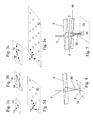
- Figs. 3a to 3e illustrate the location of light spots of beamlets within the focal plane 10 from an inclined view.
- Fig. 3a shows a circular light spot 13 in the focal plane 10 that originates from the primary laser beam 3 if no beam splitter 5 is in the path of light.
- the arrow indicates the polarisation.
- Fig. 3b shows the location of two light spots 14 generated by beamlets 6,7 in the focal plane 10 wherein the beamlets 6,7 have been created using the Wollaston prism 5 from Fig. 4.
- the orthogonal polarisation is indicated by the arrows.
- Figs. 3c, 3d, and 3e show the location of light spots in the focal plane 10 similar to Figs. 3a and 3b using a stack / cascade of 2, 3, and 4 Wollaston prisms 5, resp.
- the configuration of prisms 5,15 creating a pattern like that shown in Fig. 3c can be seen, for example, in fig. 5.
- Fig. 4 shows a schematic side view of a beam of light 3 passing a Wollaston prism 5 to impinge on a focal plane 10.
- the first laser beam 3 passes the Wollaston prism 5 from above and is split into two beamlets 6,7. In this configuration, the beamlets 6,7 cross at a crossing point 30.
- the two beamlets 6,7 impinging on the focal plane 10 show a pattern like that illustrated in Fig. 3b.
- Fig. 5 shows a schematic side view of a beam of light 3 passing two Wollaston prisms 5,15.
- each beamlet 6,7 emerging from the first Wollaston prism 5 is again split into two.
- the emerging four beamlets 16 are crossing in a common crossing point 30 and impinge then on the focal plane 10 in a pattern like that illustrated in Fig. 3c.
- the Wollaston prisms 5 are each part of a stack element (not shown) each consisting of a disc or plate, preferably made of aluminium.
- the stack elements that are rotatably arranged on top of each other.
- Each disc or plate has a central hole or bore wherein there is provided the respective Wollaston prism 5,15.
- the laser scanning device described above by reference to the figures 1 to 5 can be part of a laser scanning microscope.
- the crossing points 30 of the beamlets 6,7,16 are preferably arranged in the pupil of the microscope. This is particularly advantageous if larger stacks of prisms are used.
- the above described laser scanning device can also be used for scanning DNA-microarrays or similar microarrays having a substrate on which spots with probes are provided. The spots are optically scanned.
- laser scanners with their inherent advantages can be used also for high throughput measurements in micro array techniques, where a single beam would be too slow.
- Laser scanners here can have advantages with respect to dynamic, accuracy, signal to noise ratio etc. depending from the arrangement. Pulsed lasers could be engaged combined with time gated CCDs for high throughput lifetime measurements. This in turn allows more accurate FRET (fluorescence resonance energy transfer) measurements for example in binding studies. Two-Photon excitation with its inherent depth discrimination, and less auto-fluorescence can be applied. Of course also multiply stained samples can be imaged using appropriate laser lines and filters and optionally multiple cameras. The usage of the different polarisation of the beamlets also might be advantageously exploited if the interaction with the sample is polarisation sensitive. In these applications with micro arrays it can be advantageous not to focus the beamlets exactly onto the spots so that they cover the whole spot and/or are registered with the spots. Especially in this case the signal to noise ratio can be improved as spaces in between the spots are not illuminated.
- FRET fluorescence resonance energy transfer
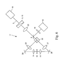
- Fig. 6 shows a 4Pi laser scanning module 17 in a schematic diagram. This module is typically run in multi-photon fluorescence mode. In a 4Pi microscope the objective turret and stage is replaced by the 4Pi module 17.
- a beam 3 from the laser scanner 18 enters the 4Pi module and is split into beamlets by a beam splitter 5,15.
- the beam consisting now of several beamlets is directed by mirrors 24,26 onto a sample simultaneously from top and bottom via two beam paths through two opposing micro-objectives 9 and 11.
- the sample is placed in a focal plane 10.
- a beamsplitter 22 (beam splitting mirror) splits the set of beamlets into two essential identical sets of beamlets.
- Lens pairs 20, 23 and 20, 27 are provided for translating the pupil of the micro objectives 9 and 11 to essentially the location where the beamsplitter 5,15 is.
- Light generated in the focus of the sample is collected by the micro-objectives 9,11 and merged at the beamsplitter 22 and directed by means of a dicroic mirror 8 to a detector 12 (ccd sensor) on which the light is focussed.
- a detector 12 ccd sensor
- an appropriate barrier filter 19 is positioned in front of the detector 12 for blocking the excitation light.
- the beam splitter 5,15 of this embodiment is fashioned in the same way as the beam splitter described above by reference to the figures 2 to 5.
- the invention can be summarised according to the following:
- the present invention relates to an optical scanning device that comprises a light source to emit a beam of light, and a beam splitter to split that beam into several beamlets, and further a first objective lens to direct said beamlets onto a focal plane wherein each of said beamlets impinges on the focal plane separated from each other, wherein the beam splitter comprises at least one birefringent element, preferably a stack of Wollaston prisms which then allows faster imaging by simulateously using multiple beams.
Landscapes
- Physics & Mathematics (AREA)
- Chemical & Material Sciences (AREA)
- Analytical Chemistry (AREA)
- General Physics & Mathematics (AREA)
- Optics & Photonics (AREA)
- Investigating, Analyzing Materials By Fluorescence Or Luminescence (AREA)
- Microscoopes, Condenser (AREA)
Priority Applications (4)
| Application Number | Priority Date | Filing Date | Title |
|---|---|---|---|
| EP05007798A EP1710609A1 (fr) | 2005-04-08 | 2005-04-08 | Appareillage à balayage optique et méthode de son développement |
| US11/910,938 US7746470B2 (en) | 2005-04-08 | 2006-03-31 | Optical scanning device and method of deriving same |
| EP06723939.2A EP1872167B1 (fr) | 2005-04-08 | 2006-03-31 | Microscope multi-photon à fluorescence |
| PCT/EP2006/002979 WO2006108526A1 (fr) | 2005-04-08 | 2006-03-31 | Dispositif de balayage optique et procede d'entrainement de celui-ci |
Applications Claiming Priority (1)
| Application Number | Priority Date | Filing Date | Title |
|---|---|---|---|
| EP05007798A EP1710609A1 (fr) | 2005-04-08 | 2005-04-08 | Appareillage à balayage optique et méthode de son développement |
Publications (1)
| Publication Number | Publication Date |
|---|---|
| EP1710609A1 true EP1710609A1 (fr) | 2006-10-11 |
Family
ID=34934932
Family Applications (2)
| Application Number | Title | Priority Date | Filing Date |
|---|---|---|---|
| EP05007798A Withdrawn EP1710609A1 (fr) | 2005-04-08 | 2005-04-08 | Appareillage à balayage optique et méthode de son développement |
| EP06723939.2A Expired - Lifetime EP1872167B1 (fr) | 2005-04-08 | 2006-03-31 | Microscope multi-photon à fluorescence |
Family Applications After (1)
| Application Number | Title | Priority Date | Filing Date |
|---|---|---|---|
| EP06723939.2A Expired - Lifetime EP1872167B1 (fr) | 2005-04-08 | 2006-03-31 | Microscope multi-photon à fluorescence |
Country Status (3)
| Country | Link |
|---|---|
| US (1) | US7746470B2 (fr) |
| EP (2) | EP1710609A1 (fr) |
| WO (1) | WO2006108526A1 (fr) |
Cited By (1)
| Publication number | Priority date | Publication date | Assignee | Title |
|---|---|---|---|---|
| WO2010133678A1 (fr) * | 2009-05-20 | 2010-11-25 | Deutsches Krebsforschungszentrum | Microscope à balayage à lumière fluorescente comportant un dispositif de mise en forme de faisceau chromatique biréfringent |
Families Citing this family (13)
| Publication number | Priority date | Publication date | Assignee | Title |
|---|---|---|---|---|
| US20080083886A1 (en) * | 2006-09-14 | 2008-04-10 | 3M Innovative Properties Company | Optical system suitable for processing multiphoton curable photoreactive compositions |
| US7551359B2 (en) * | 2006-09-14 | 2009-06-23 | 3M Innovative Properties Company | Beam splitter apparatus and system |
| JP2009086783A (ja) * | 2007-09-28 | 2009-04-23 | Fujitsu Microelectronics Ltd | フィルタ回路、フィルタ処理方法、撮像素子回路およびカメラ |
| JP5005570B2 (ja) * | 2008-02-04 | 2012-08-22 | 株式会社リコー | 画像処理装置およびプログラム |
| US7940448B2 (en) * | 2009-06-11 | 2011-05-10 | Alces Technology, Inc. | Display system |
| CN102597845B (zh) * | 2009-11-02 | 2016-06-29 | 奥林巴斯株式会社 | 分束器装置、光源装置和扫描观测装置 |
| DE202010004547U1 (de) | 2010-04-01 | 2011-10-05 | Deutsches Krebsforschungszentrum Stiftung des öffentlichen Rechts | Elektrooptische Anordnung zum ultraschnellen Abtasten eines Objektes |
| EP2694932B1 (fr) * | 2011-04-07 | 2018-02-21 | The UWM Research Foundation, Inc | Microscope à grande vitesse à résolution spectrale |
| US10036631B2 (en) * | 2012-05-01 | 2018-07-31 | Texas Department Of Transportation | System and method for measuring three-dimensional surface features |
| JP6210754B2 (ja) * | 2013-06-24 | 2017-10-11 | オリンパス株式会社 | 走査型光学顕微鏡 |
| DE102017122413A1 (de) * | 2017-09-27 | 2019-03-28 | Abberior Instruments Gmbh | Vorrichtung für das selektive Formen von Phasenfronten eines Lichtstrahls und deren Verwendung |
| US11733534B2 (en) * | 2021-01-21 | 2023-08-22 | AdlOptica Optical Systems GmbH | Optics for formation of multiple light spots with controlled spot intensity and variable spot pattern geometry |
| FR3146518B1 (fr) * | 2023-03-07 | 2025-02-07 | Office National Detudes Et De Rech Aerospatiales Onera | Dispositif de mesure optique multipoints, utilisation et procédé associés |
Citations (4)
| Publication number | Priority date | Publication date | Assignee | Title |
|---|---|---|---|---|
| US6219179B1 (en) * | 1999-02-05 | 2001-04-17 | Lavision Gmbh | Beam splitter device |
| US20010012151A1 (en) * | 2000-01-27 | 2001-08-09 | Werner Knebel | Microscope assemblage |
| FR2814247A1 (fr) * | 2000-09-18 | 2002-03-22 | Vincent Lauer | Microscope confocal a balayage laser avec formation optique de l'image |
| US6392752B1 (en) * | 1999-06-14 | 2002-05-21 | Kenneth Carlisle Johnson | Phase-measuring microlens microscopy |
Family Cites Families (3)
| Publication number | Priority date | Publication date | Assignee | Title |
|---|---|---|---|---|
| DE2713890A1 (de) * | 1976-03-30 | 1977-10-06 | Canon Kk | Optisches abtastsystem mit einem optischen system zur ausbildung von halbtonbildern |
| US5037202A (en) * | 1990-07-02 | 1991-08-06 | International Business Machines Corporation | Measurement of size and refractive index of particles using the complex forward-scattered electromagnetic field |
| US5710631A (en) * | 1995-04-11 | 1998-01-20 | International Business Machines Corporation | Apparatus and method for storing interferometric images of scanned defects and for subsequent static analysis of such defects |
-
2005
- 2005-04-08 EP EP05007798A patent/EP1710609A1/fr not_active Withdrawn
-
2006
- 2006-03-31 US US11/910,938 patent/US7746470B2/en not_active Expired - Fee Related
- 2006-03-31 EP EP06723939.2A patent/EP1872167B1/fr not_active Expired - Lifetime
- 2006-03-31 WO PCT/EP2006/002979 patent/WO2006108526A1/fr not_active Ceased
Patent Citations (4)
| Publication number | Priority date | Publication date | Assignee | Title |
|---|---|---|---|---|
| US6219179B1 (en) * | 1999-02-05 | 2001-04-17 | Lavision Gmbh | Beam splitter device |
| US6392752B1 (en) * | 1999-06-14 | 2002-05-21 | Kenneth Carlisle Johnson | Phase-measuring microlens microscopy |
| US20010012151A1 (en) * | 2000-01-27 | 2001-08-09 | Werner Knebel | Microscope assemblage |
| FR2814247A1 (fr) * | 2000-09-18 | 2002-03-22 | Vincent Lauer | Microscope confocal a balayage laser avec formation optique de l'image |
Non-Patent Citations (2)
| Title |
|---|
| DATABASE INSPEC [online] THE INSTITUTION OF ELECTRICAL ENGINEERS, STEVENAGE, GB; July 2000 (2000-07-01), EGNER A ET AL: "Time multiplexing and parallelization in multifocal multiphoton microscopy", XP002345058, Database accession no. 6630767 * |
| JOURNAL OF THE OPTICAL SOCIETY OF AMERICA A (OPTICS, IMAGE SCIENCE AND VISION) OPT. SOC. AMERICA USA, vol. 17, no. 7, 31 July 2000 (2000-07-31), pages 1192 - 1201, XP002343740, ISSN: 0740-3232 * |
Cited By (1)
| Publication number | Priority date | Publication date | Assignee | Title |
|---|---|---|---|---|
| WO2010133678A1 (fr) * | 2009-05-20 | 2010-11-25 | Deutsches Krebsforschungszentrum | Microscope à balayage à lumière fluorescente comportant un dispositif de mise en forme de faisceau chromatique biréfringent |
Also Published As
| Publication number | Publication date |
|---|---|
| EP1872167B1 (fr) | 2014-01-15 |
| US20080165358A1 (en) | 2008-07-10 |
| WO2006108526A1 (fr) | 2006-10-19 |
| US7746470B2 (en) | 2010-06-29 |
| EP1872167A1 (fr) | 2008-01-02 |
Similar Documents
| Publication | Publication Date | Title |
|---|---|---|
| Bayguinov et al. | Modern laser scanning confocal microscopy | |
| JP6967560B2 (ja) | 高分解能走査顕微鏡 | |
| JP4747243B2 (ja) | 試料の光学的深部分解による光学的把握のための方法および装置 | |
| JP6346615B2 (ja) | 光学顕微鏡および顕微鏡観察方法 | |
| JP6282706B2 (ja) | 物体の2次元または3次元の位置調整のための高解像度顕微鏡および方法 | |
| US7274446B2 (en) | Method and arrangement for the deep resolved optical recording of a sample | |
| KR100721414B1 (ko) | 공초점 현미경, 공초점 현미경을 사용한 형광 측정 방법 및편광 측정 방법 | |
| US6229635B1 (en) | Light sensing device | |
| JP5253761B2 (ja) | 走査型レーザ顕微鏡 | |
| US10310243B2 (en) | Device and method for multispot scanning microscopy | |
| CN108139578B (zh) | 分辨至少两个光谱范围的高分辨率扫描显微术 | |
| US7746470B2 (en) | Optical scanning device and method of deriving same | |
| WO2020034299A1 (fr) | Dispositif d'imagerie multi-zone parallèle | |
| JP2015215629A (ja) | 試料の構造を空間的に高分解能で結像するための装置および方法 | |
| US7746553B2 (en) | Laser scanning microscope for fluorescence testing | |
| US20060146325A1 (en) | Device for multifocal confocal microscopic determination of spatial distribution and for multifocal fluctuation analysis of fluorescent molecules and structures with flexible spectral detection | |
| JP2007233370A (ja) | 試料を高い空間分解能で検査するための方法および顕微鏡 | |
| JP5162781B2 (ja) | 顕微鏡組立物 | |
| US20250052991A1 (en) | Microscope and Method for Microscopy | |
| CN108292034A (zh) | 用于利用结构化的光片照射检查试样的方法和设备 | |
| CN120178490A (zh) | 显微镜以及借助于扫描显微镜进行扫描图像获取的方法 | |
| US7605976B1 (en) | Method and device for changing light in an adjustable manner | |
| Fuseler et al. | Types of confocal instruments: Basic principles and advantages and disadvantages | |
| CN108593620B (zh) | 一种应用于4pi显微架构的多色超分辨成像系统 | |
| Stimson et al. | A unique optical arrangement for obtaining spectrally resolved confocal images |
Legal Events
| Date | Code | Title | Description |
|---|---|---|---|
| PUAI | Public reference made under article 153(3) epc to a published international application that has entered the european phase |
Free format text: ORIGINAL CODE: 0009012 |
|
| AK | Designated contracting states |
Kind code of ref document: A1 Designated state(s): AT BE BG CH CY CZ DE DK EE ES FI FR GB GR HU IE IS IT LI LT LU MC NL PL PT RO SE SI SK TR |
|
| AX | Request for extension of the european patent |
Extension state: AL BA HR LV MK YU |
|
| AKX | Designation fees paid | ||
| STAA | Information on the status of an ep patent application or granted ep patent |
Free format text: STATUS: THE APPLICATION IS DEEMED TO BE WITHDRAWN |
|
| 18D | Application deemed to be withdrawn |
Effective date: 20070412 |
|
| REG | Reference to a national code |
Ref country code: DE Ref legal event code: 8566 |