EP1710636A1 - Hemmung für eine Uhr - Google Patents
Hemmung für eine Uhr Download PDFInfo
- Publication number
- EP1710636A1 EP1710636A1 EP05102703A EP05102703A EP1710636A1 EP 1710636 A1 EP1710636 A1 EP 1710636A1 EP 05102703 A EP05102703 A EP 05102703A EP 05102703 A EP05102703 A EP 05102703A EP 1710636 A1 EP1710636 A1 EP 1710636A1
- Authority
- EP
- European Patent Office
- Prior art keywords
- arm
- pallet
- exhaust according
- wheel
- cooperating
- Prior art date
- Legal status (The legal status is an assumption and is not a legal conclusion. Google has not performed a legal analysis and makes no representation as to the accuracy of the status listed.)
- Withdrawn
Links
- 230000010355 oscillation Effects 0.000 claims abstract description 5
- 230000000737 periodic effect Effects 0.000 claims abstract description 5
- 230000007246 mechanism Effects 0.000 abstract description 12
- 230000000284 resting effect Effects 0.000 description 11
- 210000003423 ankle Anatomy 0.000 description 6
- 230000000694 effects Effects 0.000 description 3
- 238000012423 maintenance Methods 0.000 description 2
- 230000000630 rising effect Effects 0.000 description 2
- 230000035939 shock Effects 0.000 description 2
- 230000001174 ascending effect Effects 0.000 description 1
- 239000000470 constituent Substances 0.000 description 1
- 238000010276 construction Methods 0.000 description 1
- 230000003993 interaction Effects 0.000 description 1
- 239000000696 magnetic material Substances 0.000 description 1
- 210000000056 organ Anatomy 0.000 description 1
- 230000001105 regulatory effect Effects 0.000 description 1
- 230000001131 transforming effect Effects 0.000 description 1
Images







Classifications
-
- G—PHYSICS
- G04—HOROLOGY
- G04B—MECHANICALLY-DRIVEN CLOCKS OR WATCHES; MECHANICAL PARTS OF CLOCKS OR WATCHES IN GENERAL; TIME PIECES USING THE POSITION OF THE SUN, MOON OR STARS
- G04B15/00—Escapements
- G04B15/06—Free escapements
Definitions
- the present invention relates to the field of watchmaking. It relates more particularly to a mechanical watch mechanism known as an escapement.
- the purpose of the escapement is to maintain and count the oscillations of the pendulum of a watch (or the pendulum of a clock). It receives the energy dispensed at the base by the barrel, through the finishing train, and lets periodically escape a parcel of this motive power to restore to the regulating organ that makes him lose the friction.
- the exhaust is a distributor member transforming the rotational movement of the gear train into a reciprocating movement.
- FIG. 1 An expansion escapement is shown in FIG. 1. It comprises, in a conventional manner, an escape wheel 1 connected kinematically to the cylinder, and a trigger 2.
- a double plate 3 carries a pulse pallet 4 cooperating with the wheel of FIG. exhaust 1 and a release pallet 5 working with the end of the trigger 2.
- the latter has a bend, carrying a pallet rest 6, on which can come to rest the wheel 1. springs 7 and 8 allow to maintain the different supports.
- This type of exhaust has certain disadvantages that make it particularly difficult to adapt in a wristwatch.
- it is sensitive to shocks. If a lateral shock disengages the rest pallet 6, the mechanism is racing.
- the escape wheel performs a double-jump, also called gallop.
- it is not self-starting. This means that when you raise the watch while it is stopped, it is necessary to launch the pendulum oscillating by printing a rapid rotational movement to the watch.
- the object of the present invention is to propose an exhaust system benefiting from the mechanical efficiency of a detent escapement, without presenting the disadvantages thereof.
- the periods of the limiting member and the control member correspond, respectively, to an alternation and an oscillation of the balance.
- the limiting member is formed of a first arm pivotally mounted about an axis. It ends with a fork cooperating with the peg to move between a first and a second stable positions defined by a first and second stops.
- the limiting member further comprises a pulling system ensuring the maintenance of this arm in the first and second stable positions.
- the pulling member comprises a jumper and a pallet cooperating elastically with each other and arranged one on the first arm, the other on the second arm. This draw member makes the first and second arms integral when the second leaves its stable position.
- the two arms are pivotally mounted around the same axis.
- the plate further comprises a release pallet.
- the second arm on the one hand, carries an elastic member, whose end is intended to cooperate with the release pallet and, on the other hand, extends into a spout that ends so as to be contact laterally with the elastic member, near its end.
- the spout crosses the elastic member and ends in a portion perpendicular to the plane of the arm.
- the pulling system is magnetic or comprises a bistable spring cooperating with the first arm.
- the return system comprises a portion of the second arm disposed on the other side of the pivot point and a return pallet located on this portion and intended to cooperate with the escape wheel.
- the return system is formed by edge planks associated with the teeth of the escape wheel and a return pin disposed on the second arm and intended to cooperate with the inner surface of the boards.
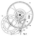
- FIG. 2 shows an escapement wheel 10 kinematically connected to the barrel (not shown) of a mechanical watch movement.
- This wheel 10 is provided with teeth 12 intended to cooperate, on the one hand, with a plate 14 mounted on a rocker 16 and, on the other hand, with an anchor 18.
- the teeth 12 have, in particular, a plane BC which, as the description below will explain, acts as a rest plane and pulse plane, and a plane AB, the intersection of the planes defining the tip of the teeth.
- the plate 14 has two levels, one lower 20 and the other upper 22, mounted coaxial.
- the lower level receives a pulse pallet 24, while an ankle 23 is disposed on the upper level 22.
- the anchor 18 is provided with a first arm 26 pivoted about an axis AA, acting as a limiting member of the stroke of the balance 16. It is of bent shape and ends with a fork 28, similar to that of a Swiss lever escapement and comprising, in particular, an inlet 28a and an outlet 28b and a stinger 28c (visible in Figures 3 to 17). Its stroke is limited by two fork stops 29, arranged on either side of the arm 26. The fork 28 cooperates with the peg 23 of the level 20.
- the anchor 18 further comprises a second arm 30 pivotally mounted with reference to the first arm, also around AA.
- This arm acts as a control member because, as will be understood below, it releases and stops the escape wheel 10.
- the pivot point separates the arm 30 into a resting portion 30a and a second 30b called recall.
- the rest portion 30a has, at its end and on its lower face, a rest lift 32 intended to cooperate with the teeth 12 of the escape wheel 10. It is also provided on its upper face with a pallet bearing 34 whose role will appear later and an opening 36 inside which is housed a stop 38. This limits the stroke of the arm 30.
- the return portion 30b ends with a return pallet 40 intended to cooperate with the teeth 12. These elements form a return system whose operation is explained below.
- this part acts as a counterweight for the part 30b and thus facilitates the pivoting of the arm 30 in the vertical positions of the mechanism.
- the arms 26 and 30 are interconnected by a jumper 44 cooperating with a wire spring 46.
- the jumper is mounted slightly pivotally in the elbow of the arm 26 and has a lug 48 near its pivot point. Its end cooperates with the pallet 34 and is shaped so as to provide two surfaces 44a and 44b of stable support on the pallet 34 which, in addition, plays the role of pulling system.
- the spring 46 is mounted on the arm 26 and acts on the lug 48 to support the jumper 44 against the pallet 34.
- the exhaust is at rest and the balance is in the downward portion of its alternation and rotates counterclockwise (SIAM below).
- the peg 23 and the impulse pallet 24 are free.
- the first bearing surface 44a of the jumper 44 cooperates with the pallet 34.
- the escape wheel 10 is fixed, the plane BC of one of its teeth 12 resting on the rest lift 32. This causes a draw now the arms 26 and 30 of the anchor 18 in a first stable position, wherein the arms 26 and 30 are respectively supported on a first of the stops 29 and on a first side of the abutment 38.
- the pallet 40 of the arm recall 30b is set back from the escape wheel 10.
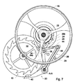
- the rocker 16 continues its alternation and the ankle 23 comes into contact with the inlet 28a of the fork 28, as is the case with a Swiss lever escapement.
- the arm 26 is then rotated about the axis AA in the direction of clockwise (SAM below).
- SAM clockwise
- the movement of the arm 30 causes the release of the escape wheel 10 which released its support on the lift rest 32.
- the wheel 10 then rotates in the SAM, kinematically driven by the barrel.
- the anchor 18 continues its pivoting movement around AA, always driven by the pin 23, which brings the pallet 40 of the return arm 30b into contact with a tooth 12.
- the pallet 40 and the arm 30b are stopped in their movement.
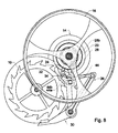
- the arm 26 is completely independent and retains its initial movement in the SAM, still under the effect of the pin 23.
- the pallet 34 leaves the first bearing surface 44a of the jumper 44 and slides to the second 44b.
- the rocker 16 and the plate 14 turn in the SAM and are in the descending portion of their next alternation.
- the second surface 44b is always resting on the pallet 34 and the wheel 10 is fixed, resting on the rest lift 32.
- the escape wheel 10 has a singing structure. More specifically, the plane AB of the teeth 12 of the escape wheel 10 is extended by a board 50 rising perpendicular to the plane of the wheel.
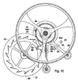
- the plate 14 has a third level 52 superimposed coaxially at the level 22 and provided with a clearance pallet 54 visible in Figure 10. It ends with a point having a straight portion 54a and a portion in a circular arc 54b.
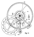
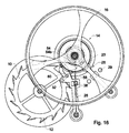
- the limitation and control members are always formed arms 26 and 30 which are each pivotally mounted on independent axes, respectively BB and CC.
- the arm 26 has only the fork 28 and a magnet 55.
- the stops 29 are made of a soft magnetic material, the attraction of which with the magnet 55 ensures the draft which keeps the anchor in its first and second stable positions.
- the arm 30 is comparable to the expansion of the exhaust mechanism of the same name shown in Figure 1. It is provided with a return pin 56 for cooperating with the inner surface of the boards 50 to provide the return system. It carries an elastic member formed of a spring 58 mounted rigid DC, substantially parallel to the longitudinal axis of its base. The end of the spring 58 is intended to cooperate with the release pallet 54 (visible in Figure 10) against the right portion 54a in alternation and against the circular portion 54b in the other half.
- the arm 30 is further extended into a spout 60. It passes under spring 58 and ends in a portion 62 rising perpendicularly to the plane of the arm 30 so as to be in lateral contact with the spring 58, near its end.
- the exhaust is at rest and the balance 16 is in the downward portion of its alternation and rotates counterclockwise (SIAM below).
- the peg 23 and the impulse pallet 24 are free.
- the escape wheel 10 is fixed, resting on the rest lift 32, which pulls the arm 30 against the abutment 38.
- the arm 26 is in its first stable position, magnetically held in abutment against a first of the stops 29.
- the return pin 56 is free, above the serge of the escape wheel 10.
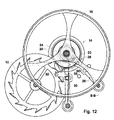
- the impulse 24 and clearance paddles 54 and the pin 23 continue their downward cycle and the latter comes into contact with the inlet 28a of the fork 28.
- the arm 26 is then rotated about the axis BB in the SAT.
- the pallet 54 meets the end of the spring 58, resting on the spout 60, which has the effect of putting the arm 30 in rotation in the SAM around the axis CC.
- the release pallet 54 continues its rotation and pushes the spring 58, the nozzle 60 preventing the latter from being deformed.
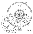
- the movement of the arm 30 causes the release of the escape wheel 10 which is no longer in contact with the rest lift 32.
- the wheel 10 then rotates in the SAM, driven kinematically by the barrel.
- the arm 26 is always rotated around BB by the ankle 23.
- the release pallet 54 continues its rotation and leaves the contact of the spring 58.
- the tooth 12 which has just left the rest lift 32 comes to rest, by its board 50, on the return pin 56.
- the force generated by this support causes the arm 30 in the SIAM, to bring it back to its original position.
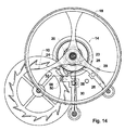
- the peg 23 continues its rotation and leaves the fork 28, the arm 26 being in the vicinity of the second stop 29.
- the pin 56 is no longer supported on the board 50 of the tooth 12, but the arm 30 is not yet quite in its rest position.
- the rocker 16 and the plate 14 complete their alternation in the SIAM.
- the peg 23 and the impulse 24 and clearance paddles 54 are free and are in the ascending portion of their alternation.
- the fork 28 is now in its second stable position, held magnetically in abutment against the second stop 29.
- the arm 30 is returned to its rest position, as described in FIG.
- the escape wheel 10 is fixed, the tooth 12 which has just given the impulse resting on the rest lift 32.
- the rocker 16 and the plate 14 turn in the SAM and are in the descending portion of their next alternation.
- the wheel 10 is fixed, resting on the rest lift 32.
- FIG. 17 illustrates a variant of this second embodiment, in which the arm 26 cooperates with a bistable spring 64, ensuring the maintenance of its first and second stable positions, resting against the stops 29.
- the passage from one to the other is always by interaction of the ankle 23 on the fork 28.
- the periods of the first arm 26 and the second arm 30 respectively correspond to an alternation and an oscillation of the balance 16.
Landscapes
- Physics & Mathematics (AREA)
- General Physics & Mathematics (AREA)
- Forklifts And Lifting Vehicles (AREA)
- Portable Nailing Machines And Staplers (AREA)
- Output Control And Ontrol Of Special Type Engine (AREA)
- Valve-Gear Or Valve Arrangements (AREA)
Priority Applications (5)
| Application Number | Priority Date | Filing Date | Title |
|---|---|---|---|
| EP05102703A EP1710636A1 (de) | 2005-04-06 | 2005-04-06 | Hemmung für eine Uhr |
| EP06725425A EP1866707A1 (de) | 2005-04-06 | 2006-03-30 | Uhrenhemmung |
| CH01724/06A CH700028B8 (fr) | 2005-04-06 | 2006-03-30 | Echappement pour montre. |
| US11/910,863 US7686503B2 (en) | 2005-04-06 | 2006-03-30 | Watch escapement |
| PCT/EP2006/061169 WO2006106066A1 (fr) | 2005-04-06 | 2006-03-30 | Echappement pour montre |
Applications Claiming Priority (1)
| Application Number | Priority Date | Filing Date | Title |
|---|---|---|---|
| EP05102703A EP1710636A1 (de) | 2005-04-06 | 2005-04-06 | Hemmung für eine Uhr |
Publications (1)
| Publication Number | Publication Date |
|---|---|
| EP1710636A1 true EP1710636A1 (de) | 2006-10-11 |
Family
ID=35839639
Family Applications (2)
| Application Number | Title | Priority Date | Filing Date |
|---|---|---|---|
| EP05102703A Withdrawn EP1710636A1 (de) | 2005-04-06 | 2005-04-06 | Hemmung für eine Uhr |
| EP06725425A Withdrawn EP1866707A1 (de) | 2005-04-06 | 2006-03-30 | Uhrenhemmung |
Family Applications After (1)
| Application Number | Title | Priority Date | Filing Date |
|---|---|---|---|
| EP06725425A Withdrawn EP1866707A1 (de) | 2005-04-06 | 2006-03-30 | Uhrenhemmung |
Country Status (4)
| Country | Link |
|---|---|
| US (1) | US7686503B2 (de) |
| EP (2) | EP1710636A1 (de) |
| CH (1) | CH700028B8 (de) |
| WO (1) | WO2006106066A1 (de) |
Cited By (7)
| Publication number | Priority date | Publication date | Assignee | Title |
|---|---|---|---|---|
| DE202009008527U1 (de) * | 2009-03-25 | 2010-08-12 | Tutima Uhrenfabrik Gmbh | Chronometerhemmung |
| ITRM20090621A1 (it) * | 2009-11-25 | 2011-05-26 | Carlo Ferrara | Scappamento per orologeria ad alto rendimento. |
| WO2011120180A1 (fr) * | 2010-04-01 | 2011-10-06 | Rolex S.A. | Dispositif de blocage pour roue dentée |
| EP2444860A1 (de) * | 2010-10-21 | 2012-04-25 | Audemars Piguet (Renaud et Papi) SA | Reguliervorrichtung für Uhr |
| EP2730980A1 (de) * | 2012-11-09 | 2014-05-14 | Nivarox-FAR S.A. | Uhrmechanismus zur Begrenzung oder Übertragung |
| CH710685A1 (fr) * | 2015-01-30 | 2016-08-15 | Sowind S A | Mécanisme d'échappement. |
| EP3293583A1 (de) * | 2016-09-07 | 2018-03-14 | Dominique Renaud SA | Hemmungsmechanismus |
Families Citing this family (14)
| Publication number | Priority date | Publication date | Assignee | Title |
|---|---|---|---|---|
| JP5366319B2 (ja) * | 2009-09-14 | 2013-12-11 | セイコーインスツル株式会社 | デテント脱進機およびそれを有する機械式時計 |
| CH702187A2 (fr) * | 2009-11-02 | 2011-05-13 | Lvmh Swiss Mft Sa | Organe réglant pour montre bracelet, et pièce d'horlogerie comportant un tel organe réglant. |
| JP5729666B2 (ja) * | 2010-09-14 | 2015-06-03 | セイコーインスツル株式会社 | 時計用デテント脱進機、および機械式時計 |
| JP5729665B2 (ja) * | 2010-09-14 | 2015-06-03 | セイコーインスツル株式会社 | 時計用デテント脱進機、および機械式時計 |
| EP2506092B1 (de) * | 2011-03-31 | 2020-01-08 | Cartier International AG | Uhrhemmungsmechanismus, insbesondere für Uhrwerk |
| CH704764A2 (fr) * | 2011-03-31 | 2012-10-15 | Cartier Creation Studio Sa | Mécanisme d'échappement notamment pour mouvement d'horlogerie. |
| EP2565729B1 (de) * | 2011-08-30 | 2018-01-31 | Breitling AG | Kalendermechanismus |
| EP2706416B1 (de) | 2012-09-07 | 2015-11-18 | The Swatch Group Research and Development Ltd | Flexibler Anker mit konstanter Kraft |
| KR20170125803A (ko) * | 2014-12-09 | 2017-11-15 | 엘브이엠에이치 스위스 매뉴팩츄어스 에스에이 | 시계용 장치 및 상기 장치를 구비한 시계 |
| CH710662A1 (de) * | 2015-01-16 | 2016-07-29 | Creaditive Ag | Regelorgan und Verfahren zum Betreiben eines Regelorgans mit konstanter Energie. |
| EP3179316B1 (de) * | 2015-12-10 | 2021-09-15 | Nivarox-FAR S.A. | Kontaktlose zylindrische uhrhemmung |
| CN108700845B (zh) * | 2015-12-21 | 2020-08-04 | 迪特拉有限公司 | 钟表擒纵装置和该装置的操作方法 |
| EP3339982B1 (de) * | 2016-12-23 | 2021-08-25 | The Swatch Group Research and Development Ltd | Regulierung durch mechanisches bremsen eines mechanischen oszillators einer uhr |
| EP3584645B1 (de) * | 2018-06-19 | 2021-06-30 | The Swatch Group Research and Development Ltd | Uhr, die ein mechanisches uhrwerk umfasst, dessen ganggenauigkeit durch eine elektromechanische vorrichtung reguliert wird |
Citations (2)
| Publication number | Priority date | Publication date | Assignee | Title |
|---|---|---|---|---|
| CH101849A (fr) * | 1922-10-25 | 1923-11-16 | Pellaton Jules | Echappement de mouvement de montre. |
| GB842150A (en) * | 1955-10-31 | 1960-07-20 | Zen Ichi Inotsume | Improvements relating to timekeepers having detached escapements |
Family Cites Families (5)
| Publication number | Priority date | Publication date | Assignee | Title |
|---|---|---|---|---|
| US3538705A (en) * | 1968-11-07 | 1970-11-10 | Hamilton Watch Co | Escapement |
| EP0018796B1 (de) * | 1979-04-30 | 1984-11-07 | George Daniels | Uhren, Pendeluhren, Chronometer und Hemmungen dafür |
| ATE363673T1 (de) * | 2003-12-04 | 2007-06-15 | Montres Breguet Sa | Chronometerhemmung für armbanduhren |
| DE602005023633D1 (de) * | 2004-10-26 | 2010-10-28 | Tag Heuer Sa | Armbanduhr-regulierungsglied und mechanisches uhrwerk mit einem solchen regulierungsglied |
| EP1770452A1 (de) * | 2005-09-30 | 2007-04-04 | Peter Baumberger | Chronometerhemmung für Uhren |
-
2005
- 2005-04-06 EP EP05102703A patent/EP1710636A1/de not_active Withdrawn
-
2006
- 2006-03-30 WO PCT/EP2006/061169 patent/WO2006106066A1/fr not_active Ceased
- 2006-03-30 EP EP06725425A patent/EP1866707A1/de not_active Withdrawn
- 2006-03-30 US US11/910,863 patent/US7686503B2/en not_active Expired - Fee Related
- 2006-03-30 CH CH01724/06A patent/CH700028B8/fr unknown
Patent Citations (2)
| Publication number | Priority date | Publication date | Assignee | Title |
|---|---|---|---|---|
| CH101849A (fr) * | 1922-10-25 | 1923-11-16 | Pellaton Jules | Echappement de mouvement de montre. |
| GB842150A (en) * | 1955-10-31 | 1960-07-20 | Zen Ichi Inotsume | Improvements relating to timekeepers having detached escapements |
Cited By (16)
| Publication number | Priority date | Publication date | Assignee | Title |
|---|---|---|---|---|
| DE202009008527U1 (de) * | 2009-03-25 | 2010-08-12 | Tutima Uhrenfabrik Gmbh | Chronometerhemmung |
| ITRM20090621A1 (it) * | 2009-11-25 | 2011-05-26 | Carlo Ferrara | Scappamento per orologeria ad alto rendimento. |
| WO2011064682A1 (en) * | 2009-11-25 | 2011-06-03 | Carlo Ferrara | High efficiency escapement |
| US8579498B2 (en) | 2009-11-25 | 2013-11-12 | Sergio Ferrara | High efficiency escapement |
| US8882339B2 (en) | 2010-04-01 | 2014-11-11 | Rolex S.A. | Immobilizing device for a toothed wheel |
| WO2011120180A1 (fr) * | 2010-04-01 | 2011-10-06 | Rolex S.A. | Dispositif de blocage pour roue dentée |
| CN102971678A (zh) * | 2010-04-01 | 2013-03-13 | 劳力士有限公司 | 用于齿轮的制动装置 |
| CN102971678B (zh) * | 2010-04-01 | 2015-07-22 | 劳力士有限公司 | 用于齿轮的制动装置 |
| EP2444860A1 (de) * | 2010-10-21 | 2012-04-25 | Audemars Piguet (Renaud et Papi) SA | Reguliervorrichtung für Uhr |
| CN103809421A (zh) * | 2012-11-09 | 2014-05-21 | 尼瓦洛克斯-法尔股份有限公司 | 钟表的防脱扣机构 |
| EP2730980A1 (de) * | 2012-11-09 | 2014-05-14 | Nivarox-FAR S.A. | Uhrmechanismus zur Begrenzung oder Übertragung |
| US9317015B2 (en) | 2012-11-09 | 2016-04-19 | Nivarox-Far S.A. | Timepiece anti-trip mechanism |
| CN103809421B (zh) * | 2012-11-09 | 2017-09-08 | 尼瓦洛克斯-法尔股份有限公司 | 钟表的防脱扣机构 |
| CH710685A1 (fr) * | 2015-01-30 | 2016-08-15 | Sowind S A | Mécanisme d'échappement. |
| EP3293583A1 (de) * | 2016-09-07 | 2018-03-14 | Dominique Renaud SA | Hemmungsmechanismus |
| WO2018046563A1 (fr) | 2016-09-07 | 2018-03-15 | Dominique Renaud Sa | Mecanisme d'echappement |
Also Published As
| Publication number | Publication date |
|---|---|
| US7686503B2 (en) | 2010-03-30 |
| EP1866707A1 (de) | 2007-12-19 |
| US20080279052A1 (en) | 2008-11-13 |
| CH700028B8 (fr) | 2010-08-13 |
| WO2006106066A1 (fr) | 2006-10-12 |
| CH700028B1 (fr) | 2010-06-15 |
Similar Documents
| Publication | Publication Date | Title |
|---|---|---|
| CH700028B1 (fr) | Echappement pour montre. | |
| EP1941326B1 (de) | Chronometerhemmung für uhrenstück | |
| EP2105806B1 (de) | Hemmungsmechanismus | |
| EP2761378B1 (de) | Stimmgabeloszillator für ein mechanisches uhrwerk | |
| EP2048548B1 (de) | Schlagwerk | |
| EP2893403A1 (de) | Flexible palettenanordnung mit konstanter kraft | |
| CH706274B1 (fr) | Mécanisme d'échappement horloger comprenant un mécanisme flexible monobloc pour la transmission d'impulsions entre le balancier et la roue d'échappement. | |
| EP1736838B1 (de) | Uhr | |
| CH712631B1 (fr) | Echappement pour mouvement d'horlogerie. | |
| EP3040783B1 (de) | Untereinheit für einen mechanismus zur einstellung der geschwindigkeit in einem uhrwerk, und ein solcher mechanismus | |
| EP2781965B1 (de) | Kassette für Uhrwerksmechanismus | |
| EP3781994B1 (de) | Restanker-hemmungmechanismus und uhrzeit mit einem solchen hemmungmechanismus | |
| EP2697693B1 (de) | Uhrwerk | |
| EP3121661A1 (de) | Direkter uhrhemmungsmechanismus mit konstanter kraft | |
| EP3185083A1 (de) | Mechanischer uhrmechanismus mit einer ankerhemmung | |
| EP3510449B1 (de) | Hemmungsmechanismus | |
| EP3338144A1 (de) | Bistabile mechanische vorrichtung, insbesondere für uhren | |
| CH714992A1 (fr) | Régulateur horloger mécanique. | |
| EP3663869A1 (de) | Schlagwerkmechanismus einer uhr mit hängehammer | |
| CH715617A2 (fr) | Mécanisme de sonnerie d'horlogerie à marteau suspendu. | |
| EP3663868B1 (de) | Uhrwerk, das ein tourbillon mit einem festen magnetischen rad umfasst | |
| CH720506A2 (fr) | Mécanisme de tourbillon pour mouvement horloger | |
| CH702853B1 (fr) | Mouvement horloger comprenant un tourbillon. | |
| EP4418051A1 (de) | Tourbillonmechanismus für uhrwerk | |
| CH704784B1 (fr) | Echappement à ancre comprenant deux roues d'échappement. |
Legal Events
| Date | Code | Title | Description |
|---|---|---|---|
| PUAI | Public reference made under article 153(3) epc to a published international application that has entered the european phase |
Free format text: ORIGINAL CODE: 0009012 |
|
| AK | Designated contracting states |
Kind code of ref document: A1 Designated state(s): AT BE BG CH CY CZ DE DK EE ES FI FR GB GR HU IE IS IT LI LT LU MC NL PL PT RO SE SI SK TR |
|
| AX | Request for extension of the european patent |
Extension state: AL BA HR LV MK YU |
|
| AKX | Designation fees paid | ||
| REG | Reference to a national code |
Ref country code: DE Ref legal event code: 8566 |
|
| STAA | Information on the status of an ep patent application or granted ep patent |
Free format text: STATUS: THE APPLICATION IS DEEMED TO BE WITHDRAWN |
|
| 18D | Application deemed to be withdrawn |
Effective date: 20070502 |