EP1710652A1 - Dispositif de servocommande bilaterale - Google Patents
Dispositif de servocommande bilaterale Download PDFInfo
- Publication number
- EP1710652A1 EP1710652A1 EP04703491A EP04703491A EP1710652A1 EP 1710652 A1 EP1710652 A1 EP 1710652A1 EP 04703491 A EP04703491 A EP 04703491A EP 04703491 A EP04703491 A EP 04703491A EP 1710652 A1 EP1710652 A1 EP 1710652A1
- Authority
- EP
- European Patent Office
- Prior art keywords
- sensor
- output
- control device
- master
- slave
- Prior art date
- Legal status (The legal status is an assumption and is not a legal conclusion. Google has not performed a legal analysis and makes no representation as to the accuracy of the status listed.)
- Withdrawn
Links
Images


Classifications
-
- B—PERFORMING OPERATIONS; TRANSPORTING
- B62—LAND VEHICLES FOR TRAVELLING OTHERWISE THAN ON RAILS
- B62D—MOTOR VEHICLES; TRAILERS
- B62D15/00—Steering not otherwise provided for
- B62D15/02—Steering position indicators ; Steering position determination; Steering aids
- B62D15/021—Determination of steering angle
- B62D15/0215—Determination of steering angle by measuring on the steering column
-
- B—PERFORMING OPERATIONS; TRANSPORTING
- B62—LAND VEHICLES FOR TRAVELLING OTHERWISE THAN ON RAILS
- B62D—MOTOR VEHICLES; TRAILERS
- B62D6/00—Arrangements for automatically controlling steering depending on driving conditions sensed and responded to, e.g. control circuits
- B62D6/08—Arrangements for automatically controlling steering depending on driving conditions sensed and responded to, e.g. control circuits responsive only to driver input torque
- B62D6/10—Arrangements for automatically controlling steering depending on driving conditions sensed and responded to, e.g. control circuits responsive only to driver input torque characterised by means for sensing or determining torque
-
- B—PERFORMING OPERATIONS; TRANSPORTING
- B64—AIRCRAFT; AVIATION; COSMONAUTICS
- B64C—AEROPLANES; HELICOPTERS
- B64C13/00—Control systems or transmitting systems for actuating flying-control surfaces, lift-increasing flaps, air brakes, or spoilers
- B64C13/24—Transmitting means
- B64C13/38—Transmitting means with power amplification
- B64C13/50—Transmitting means with power amplification using electrical energy
- B64C13/505—Transmitting means with power amplification using electrical energy having duplication or stand-by provisions
-
- B—PERFORMING OPERATIONS; TRANSPORTING
- B60—VEHICLES IN GENERAL
- B60T—VEHICLE BRAKE CONTROL SYSTEMS OR PARTS THEREOF; BRAKE CONTROL SYSTEMS OR PARTS THEREOF, IN GENERAL; ARRANGEMENT OF BRAKING ELEMENTS ON VEHICLES IN GENERAL; PORTABLE DEVICES FOR PREVENTING UNWANTED MOVEMENT OF VEHICLES; VEHICLE MODIFICATIONS TO FACILITATE COOLING OF BRAKES
- B60T2220/00—Monitoring, detecting driver behaviour; Signalling thereof; Counteracting thereof
- B60T2220/04—Pedal travel sensor, stroke sensor; Sensing brake request
-
- B—PERFORMING OPERATIONS; TRANSPORTING
- B60—VEHICLES IN GENERAL
- B60T—VEHICLE BRAKE CONTROL SYSTEMS OR PARTS THEREOF; BRAKE CONTROL SYSTEMS OR PARTS THEREOF, IN GENERAL; ARRANGEMENT OF BRAKING ELEMENTS ON VEHICLES IN GENERAL; PORTABLE DEVICES FOR PREVENTING UNWANTED MOVEMENT OF VEHICLES; VEHICLE MODIFICATIONS TO FACILITATE COOLING OF BRAKES
- B60T2270/00—Further aspects of brake control systems not otherwise provided for
- B60T2270/82—Brake-by-Wire, EHB
-
- G—PHYSICS
- G05—CONTROLLING; REGULATING
- G05B—CONTROL OR REGULATING SYSTEMS IN GENERAL; FUNCTIONAL ELEMENTS OF SUCH SYSTEMS; MONITORING OR TESTING ARRANGEMENTS FOR SUCH SYSTEMS OR ELEMENTS
- G05B2219/00—Program-control systems
- G05B2219/30—Nc systems
- G05B2219/42—Servomotor, servo controller kind till VSS
- G05B2219/42318—Using two, more, redundant measurements or scales to detect bad function
Definitions
- the present invention relates to a master-slave control system using a bilateral servo control device, and more particularly to a force feedback or parallel bilateral servo control device in which a reaction force of the slave (effecting end) acts on the master (operating end) such that an effecting force awareness can be obtained.
- Fly-by-wire in aircraft control and X-by-wire in automotive control are good examples, in which a master-slave control system is constructed of a master as an operating end and a slave as an effecting end.
- Such systems are constructed as bilateral servo control devices in which a reaction force produced by the movement of the slave is fed back to the master such that an effecting force awareness can be obtained on the master end (see JP Patent Publication (Kokai) Nos. 10-202558 A (1998 ) and 2003-11838 A , for example).
- Bilateral servos can be generally divided into the symmetric type, force-feedback type, force-reflecting type, and parallel type, as noted in a reference document (http://paradise.kz.tsukuba.ac.jp/ ⁇ labnhp/labo/study/force/bilateral.html).
- the force-feedback type and the parallel type are superior to the symmetric type and the force-reflecting type in terms of operability. However, they require a position (angle) sensor and a force (torque) sensor.
- the target position (angle) of the slave is determined in accordance with the output of a master position (angle) sensor, and the master is fitted with a force (torque) sensor for improving the response characteristics of the reaction force to the master.
- the slave performs slave position control based on the positional deviation between the master and the slave, while the master performs master force control based on the deviation of force between the master and the slave.
- the steer-by-wire that electrically controls the steering is required to have a particularly high level of reliability because of the absence of the steering position at which safety can be ensured in case of failure (fail-safe position).
- Conventional techniques for increasing the reliability of the steer-by-wire include a method whereby a fail-safe is activated upon failure by switching the hydraulic routes for the entirety of the hydraulic pressure (see, e.g., JP Patent Publication (Kokai) No. 7-125643 A (1995 )) and a method whereby the vehicle is controlled so that it turns by braking in case of failure of the steer-by-wire system (see, e.g., JP Patent Publication (Kokai) Nos. 11-334559 A (1999 ) and 2003-63373 A ).
- a master position (or angle, in the case of rotary motion) sensor and a force (or torque, in the case of rotary motion) sensor which are required in a force-feedback and parallel bilateral servo configuration, are used as mutually redundant sensors, so as to increase the reliability of the bilateral servo in which the reaction force from the slave (effecting end) acts on the master (operating end).
- the force-feedback bilateral servo device and the parallel bilateral servo device require a position (angle) sensor and a force (torque) sensor. By using these sensors as mutually redundant sensors, resistance against sensor failures can be provided.
- a target position (angle) of the slave is determined by the output of the master position (angle) sensor, wherein the master is provided with a force (torque) sensor for improving the response characteristics of reaction force to the master.
- the slave target position (angle) is determined by the output of the master force (torque) sensor.
- a target position (angle) of the slave is determined by the output of the master force (torque) sensor, wherein the master is provided with a position (angle) sensor for improving the response characteristics of reaction force to the master.
- the slave target position (angle) is determined by the output of the master position (angle) sensor.
- the target position (angle) of the slave can be determined by a sensor other than the failed sensor, thus allowing the control operation to proceed.
- the invention provides the following bilateral servo control devices (a) to (1):
- the target position (angle) of the slave can be determined by substituting one sensor for another that has failed, thereby allowing a control operation to continue. Furthermore, because the sensors that are originally provided for bilateral servo are utilized as redundant sensors, a control device having a predetermined reliability can be provided with a lower sensor redundancy.
- Fig. 1 shows the basic configuration of a bilateral servo control device according to the invention.
- the bilateral servo control device includes a master 100 as an operating end, a slave 200 as an effecting end, a slave controller 30, and a master controller 40.
- the master 100 includes a position (angle) sensor 101 and a force (torque) sensor 102 and produces a normal sensor output (first sensor output) that is a sensor output for the original slave control, and an auxiliary sensor output (second sensor output) that is a sensor output for the reaction force control output of the bilateral servo.
- the slave controller 30 receives the normal sensor output and the auxiliary sensor output from the master 100, determines a control target value for the slave 200 based on the normal sensor output and the auxiliary sensor output, and produces a control output Ys based on the thus determined control target value and a sensor output from the slave 200.
- the master controller 40 outputs a reaction force control output Ym based on the difference between the auxiliary sensor output and a reaction force target value outputted from the master 100.
- an output Xm of the position (angle) sensor of the master 100 corresponds to the normal sensor output
- an output Fm of the master force (torque) sensor corresponds to the auxiliary sensor output
- the output Fm of the force (torque) sensor of the master 100 corresponds to the normal sensor output
- the output Xm of the master position (angle) sensor corresponds to the auxiliary sensor output.
- the amount of operation of the slave 200 namely, the control output Ys
- the amount of operation of the slave 200 is determined by both the output Xm of the position (angle) sensor and the output Fm of the force (torque) sensor of the master 100, so that ⁇ Ys/ ⁇ Xm ⁇ 0 and ⁇ Ys/ ⁇ Fm ⁇ 0. In this way, failure of the position sensor and the force sensor of the master 100 can be tolerated.
- Fig. 2 shows an embodiment of the device of the invention as a force-feedback bilateral servo control device.
- a master 100 includes a position (angle) sensor 101 that is a first sensor, and a force (torque) sensor 102 that is a second sensor.
- a slave 200 includes a position (angle) sensor 201 and a force (torque) sensor 202.
- the position (angle) sensor 101 provided in the master 100 outputs a position (angle) sensor output Xm as a normal sensor output.
- the position (angle) sensor output Xm constitutes a position (angle) target value for the slave 200.
- a deviation of the output Xs of the position (angle) sensor 201 of the slave 200 from the target value is calculated at a summing point (calculator) 501 and fed to a servo controller 300.
- the position (angle) sensor output Xm of the master 100 may be multiplied by a coefficient to calculate the position (angle) target value of the slave 200.
- the servo controller 300 produces a control output Ys to the slave 200 based on the deviation between the position (angle) target value Xm and the position (angle) sensor output Xs.
- the output Fs of the force (torque) sensor 202 of the slave 200 constitutes a target value of reaction force to the master 100
- the deviation of the output Fm of the force (torque) sensor 102 of the master 100, which is the auxiliary sensor output, from the reaction force target value that is calculated at the summing point (calculator) 503 is fed to a servo controller 400.
- the servo controller 400 produces a control output Ym to the master 100 based on the deviation between the reaction force target value Fs and the force (torque) sensor output Fm.
- the force (torque) sensor output Fs of the slave 200 may be multiplied with a coefficient to calculate the target value of reaction force to the master 100.
- the transfer function of the servo controller 400 is determined in the same way as the aforementioned transfer function of the controller 300.
- the force (torque) sensor output Fm of the master 100 which is the auxiliary sensor output, is fed to a summing point (calculator) 502 via a proportional calculation factor (function generator or gain setting unit) 310 having a transfer function H(s).
- a proportional calculation factor function generator or gain setting unit 310 having a transfer function H(s).
- H(s) transfer function
- the force (torque) sensor output Fm of the master 100 is added to the position (angle) sensor output Xm of the master 100, which is the normal sensor output.
- the proportional calculation factor 310 performs a calculation in accordance with a function represented by the transfer function H(s) of the force (torque) sensor output Fm of the master 100 and outputs a value having a correlation with the force (torque) sensor output Fm.
- the summed value at the summing point 502 constitutes the position (angle) target value of the slave 200.
- the deviation of the position (angle) sensor output Xm of the slave 200 from the target value is fed to the servo controller 300, which then produces the control output Ys to the slave 300 based on the deviation.
- the slave 200 can be controlled not only by the position (angle) sensor output Xm of the master 100, which is a normal sensor output, but also by the force (torque) sensor output Fm of the master, which is an auxiliary sensor output.
- the slave 200 can be controlled by the sensor output Fm of the force (torque) sensor 102 of the master 100, which is the auxiliary sensor output.
- the behavior of the slave 200 namely, the vehicle, is fed back via an operator H to the master 100, namely, a controlling/operating unit such as the steering column (steering wheel) or the brake pedal. Therefore, as long as the slave 200 can be controlled by the master 100, no total loss of control would be produced even though a slight deterioration of operability might be caused.
- Fig. 3 shows another embodiment of the force-feedback bilateral servo control device of the invention.
- a value produced by a reaction force generating unit 410 constitutes a target value of reaction force to the master 100.
- the difference between the force (torque) sensor output Fm of the master 100 and the target value is fed to a servo controller 400, which calculates the control output Ym to the master 100.
- An example of method for generating reaction force in the reaction force generating unit 401 is a method whereby, as shown in Fig. 4 showing a steer-by-wire application, reaction force is generated from lateral acceleration Gy that is the output of a lateral acceleration sensor 203 attached to a slave (vehicle body) and yaw rate ⁇ that is the output of a yaw rate sensor 204.
- Fig. 5 Another example is shown in Fig. 5, whereby reaction force is generated from the output Xm of the position (angle) sensor of the master 100.
- the yaw rate ⁇ or the output Xm of the position (angle) sensor could be simply multiplied by a certain coefficient to generate a target value of reaction force that is proportional to the value of the yaw rate or the sensor output.
- a deceleration sensor 205 (see Fig. 4) could be used instead of the yaw rate sensor 204 so as to produce a value proportional to deceleration as the target value of reaction force.
- an advantage that relates to the generation of the reaction force target value can be gained that the force (torque) sensor 202 of the slave 200 can be eliminated.
- Fig. 6 shows another embodiment of the force-feedback bilateral servo control device of the invention.
- the output Xm of the position (angle) sensor of the master 100 is used as the target value of the lateral acceleration Gy of the slave 200 or the yaw rate ⁇ .
- the deviation of the lateral acceleration Gy of the slave 200 or yaw rate ⁇ from the target value Xm is fed to the servo controller 300.
- the servo controller 300 then generates the control output Ys to the slave 200 based on the deviation.
- a conventional technique for generating reaction force based on the output Xm of a position (angle) sensor of the master 100 is also disclosed in JP Patent Publication (Kokai) No. 2003-11838 A .
- This technique can be applied to the force-feedback bilateral servo control device of the invention, as shown in Fig. 8.
- the vehicle cannot be controlled if the position (angle) sensor 101 for detecting the angle ⁇ h of the steering wheel 110 fails.
- steering control of the vehicle can be performed by the servo controller 300 based on the torque Th of the steering wheel 110, namely, the force applied for operating the steering wheel 110.
- the slave 200 can be controlled not only by the output Xm of the position (angle) sensor of the master 100 but also by the output Fm of the force (torque) sensor of the master 100, as in the embodiment shown in Fig. 2.
- the slave 200 can be controlled by means of the output Fm of the force (torque) sensor of the master 100.
- Fig. 9 shows an embodiment of the present invention as a parallel bilateral servo control device.
- parts corresponding to those of Fig. 2 are designated with reference signs similar to those of Fig. 1 for the sake of simplicity.
- the parallel bilateral servo control device includes a position command generating unit 600.
- a master force (torque) sensor output Fm and a slave force (torque) sensor output Fs are fed to a summing point (calculator) 511.
- the position command generating unit 600 generates a position (angle) target value of the master 100 and the slave 200 based on the output of the summing point (calculator) 511, namely, the output Fm of the force (torque) sensor of the master 100, which is normal sensor outputs of the parallel bilateral servo control device, and the output Fs of the force (torque) sensor of the slave 200.
- the output Xs of the position (angle) sensor of the slave 200 is subtracted from the position (angle) target value generated by the position command generating unit 600 so as to calculate a deviation, which is fed to a servo controller 300.
- the servo controller 300 then generates a control output Ys to the slave 200 based on the deviation.
- the auxiliary sensor output namely, the output Xm of the position (angle) sensor of the master 100 is subtracted at the summing point (calculator) 513 from the position (angle) target value generated by the position command generating unit 600 so as to calculate a deviation.
- the deviation is fed to a servo controller 400, which then generates a control output Ym to the master 100 based on the deviation.
- the output Xm of the position (angle) sensor of the master 100 which is the auxiliary sensor output, is added, via a proportional calculation factor 310 based on the transfer function H(s), to the output Fm of the force (torque) sensor of the master 100, which is the normal sensor output, at a summing point (calculator) 514.
- the sum output is fed to the position command generating unit 600 together with the output Fs of the force (torque) sensor of the slave 200.
- the position command generating unit 600 then generates position (angle) target values of the master 100 and slave 200 based on the thus fed outputs.
- the slave 200 can be controlled not only by the output Fm of the force (torque) sensor of the master 100, which is the normal sensor output, but also by the output Xm of the position (angle) sensor of the master 200, which is the auxiliary sensor output.
- the slave 200 can be controlled by the output Xm of the position (angle) sensor 101 of the master 100, which is the auxiliary sensor output, in case the force (torque) sensor 102 of the master 100, which is the normal sensor output, fails.
- Fig. 10 shows another embodiment of the invention as a parallel bilateral servo control device.
- the difference (output at a summing point 513) between the output Xm of the position (angle) sensor of the master 100, which is the auxiliary sensor output, and a control target value generated by the position command generating unit 600 is added via a proportional calculation factor 310 to the output Fm of the force (torque) sensor of the master, which is the normal sensor output, at a summing point 514.
- the sum is then fed to the position command generating unit 600 together with the output Fs of the force (torque) sensor of the slave 200.
- the position command generating unit 600 Based on this input, the position command generating unit 600 generates position (angle) target values of the master 100 and the slave 200.
- a control deviation of the master 100 namely, the difference between the output Xm of the position (angle) sensor of the master 100, which is the auxiliary sensor output, and the control target value of the master 100 is produced.
- the slave 200 can also be controlled by the control deviation.
- the slave 200 can be controlled by the output Xm of the position (angle) sensor 102 of the master 100, which is the auxiliary sensor output, in case the force (torque) sensor 101 of the master 100, which produces the normal sensor output, fails.
- Fig. 11 shows another embodiment of the force-feedback bilateral servo control device according to the invention.
- a proportional calculation factor 310 includes a dead band near zero.
- the output Fm of the force (torque) sensor of the master 100 which is the auxiliary sensor output, is not always added to the output Xm of the position (angle) sensor of the master, which is the normal sensor output, but added only when more than a predetermined force (torque) is applied to the master 100.
- the slave is controlled by the output Fm of the force (torque) sensor of the master 100 only when the operator applied an effecting force that exceeds a predetermined level such that it is interpreted by the control system to be an emergency.
- the present embodiment can be applied not only to the bilateral servo control device of the type shown in Fig. 2 but also to that of the type shown in Figs. 3 to 9 as long as the proportional calculation factor 310 is provided with a dead band.
- Fig. 12 shows another embodiment of the force-feedback bilateral servo control device of the invention.
- redundancy is introduced into the output Xm of the position (angle) sensor of a master 100, and a position (angle) target value of a slave 200 is set based on a majority voting of the redundant outputs Xm of the position (angle) sensor of the master 100 together with the output Fm of the force (torque) sensor of the master 100.
- the outputs Xm of the position (angle) sensor and the output Fm of the force (torque) sensor of the master 100 represent numerical data. Therefore, if a simple majority is taken of the data, no complete agreement of values would be obtained due to sensor errors and quantization error during analog-to-digital conversion. Thus, instead of the operation to take a simple majority, an operation to take an intermediate value or an average value could be considered.
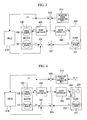
- Fig. 13 shows another embodiment of the force-feedback bilateral servo control device of the invention.
- the embodiment is provided with an examining unit (examining means) 320 for examining the output Xm of the position (angle) sensor of the master 100, which is the normal sensor output, and with a selection switch sel that is switched depending on the result of examination in the examination unit 320.
- the selection switch sel is used for selecting one of the output Xm of the master position (angle) sensor, which is the normal sensor output, and the output Fm of the master force (torque) sensor, which is the auxiliary sensor output. If the result of examination by the examination unit 320 is normal, the output Xm of the master position (angle) sensor is selected. On the other hand, if the examination unit 320 detects abnormality in the output Xm of the position (angle) sensor of the master 100, the selection switch selects the output Fm of the master force (torque) sensor.
- the examination unit 320 may employ a method whereby the unit considers the output Xm of the master position (angle) sensor, which is the normal sensor output, to be normal if the value thereof is within a certain range and abnormal if it is outside such range. It may alternatively employ a method whereby redundancy is introduced into the output Xm of the master position (angle) sensor and whereby the outputs are considered to be normal if differences among them are within a certain range and abnormal if they are not within such range.
- Fig. 14 shows an embodiment of a steer-by-wire master 100, specifically the steering column of a vehicle such as an automobile.
- the master 100 includes a steering wheel 110, torque sensor 111, angular sensor 112, and reaction force actuator 113.
- the reaction force actuator 104 which may be an electric motor such as a brushless motor, is drivingly connected to the rotary shaft (steering wheel axle) 110 via a speed-reduction mechanism as needed.
- the angular sensor 112 which detects the angle Xm of rotation of the steering wheel 110 from a center position, is provided as a means for determining the amount of rotation of the steering wheel 110 from the center position.
- the torque sensor 111 for determining a torque Fm is provided as a means for determining an operation force and a reaction force applied to the steering wheel 110.
- Redundancy may be introduced into the torque sensor 111 and the angular sensor 112 in the form of torque sensors 111-1 to 111-n and angular sensors 112-1 to 112-n, as shown in Fig. 15, so that the embodiment shown in Fig. 12 can be implemented.
- Fig. 16 shows an embodiment of a steer-by-wire slave 200, specifically the steering mechanism (vehicle body) of a vehicle such as an automobile.
- the steering mechanism includes steering wheels (tires) 210, a steering transmission mechanism 211, a steering actuator 212, an angular sensor 213, and a torque sensor 214.
- the steering actuator 212 may be comprised of a known electric motor, such as a blushless motor, for example.
- the steering transmission mechanism 211 may be comprised of a known mechanism and is not particularly limited as long as it is capable of transmitting the motion of the steering actuator 212 to the steering wheels 210 such that the steering angle can be varied.
- the steering transmission mechanism 211 may be comprised of a motion conversion mechanism, such as a ball screw mechanism, for converting a rotary motion of the output shaft of the steering actuator 212 into a linear motion of the steering rod, which is not shown.
- the movement of the steering rod is transmitted to the steering wheels 210 via a tie rod and a knuckle arm, both of which are not shown, whereby the toe angle of the steering wheels 211 can be changed.
- the steering transmission mechanism 211 may be comprised of a combination of a pinion gear coupled with the output shaft of the steering actuator 212 and a rack bar connected to the tie rod, instead of the ball screw mechanism.
- the steering angle Xs of the steering mechanism is detected by the angular sensor 213.
- the torque Fs is detected by the torque sensor 214.
- the slave 200 may be provided with a lateral accelerometer or yaw rate sensor 215, and its output, namely, lateral acceleration Gy or yaw rate ⁇ , may be used as a representative value of reaction force on the slave end.
- the torque sensor 214 can be eliminated, as shown in Fig. 18.
- the angular sensor 213 and the torque sensor 214 may be redundantly provided as angular sensors 213-1 to 213-n and torque sensors 214-1 to 214-n, as shown in Fig. 19.
- Fig. 20 shows an embodiment of a brake-by-wire master 100, specifically a stroke simulator.
- the master 100 includes a brake pedal 120, force sensor 121, angular sensor 122, and reaction force actuator 123, which are connected with a rotary shaft 124 supported rotatably at its end on the vehicle side.
- the angular sensor 122 detects the amount of depression of the brake pedal 120, while the force applied is detected by the force sensor 121.
- the force sensor 121 and the angular sensor 122 may be redundantly provided as needed for improving reliability.
- Fig. 21 shows an embodiment of a brake-by-wire slave 200, specifically an electric brake.
- the electric brake includes a brake-driving actuator 220, motion conversion mechanism 221, brake pad 222, brake disc 226 fitted on an axle 225 of the wheels 224, position sensor 227, and force sensor 228.
- a rotary motion about the motor output axis generated by the brake-driving actuator 220 is converted into a linear motion by the motion conversion mechanism 221.
- the brake pad 222 is pressed against the brake disc 226, thereby producing a braking force.
- the position of the brake pad 222 is detected by the position sensor 227, while the pressing force is detected by the force sensor 228.
- the control system for the brake-by-wire system may be based on the bilateral servo control devices shown in Figs. 2 to 13. However, because the braking force is proportional to the pressing force of the brake pad 222, the control system preferably employs the output Fm of the force sensor of the master 100 as a control target value. In this case, too, reliability can be improved by the apparatus of the invention in which the output Xm of the position sensor is fed back to the master 100 for position feedback, as shown in Fig. 22.
- Fig. 23 shows an embodiment of a fly-by-wire master 100, specifically a control column or a side stick.
- the master 100 includes an operating member 130, such as a control column or side stick installed in the flight deck, torque sensor 131, position (angle) sensor 132, and reaction force actuator 133, which are mutually coupled via a rotary shaft 134.
- the amount of operation of the control column or side stick 112 is detected by the position (angle) sensor 132.
- the force or reaction force of the control column or side stick is detected by the torque sensor 131.
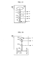
- Fig. 24 shows an embodiment of a fly-by-wire slave 200, specifically a control surface device.
- the control surface device includes a control surface 230, driving actuator 231, torque sensor 232, and angular sensor 233, which are mutually coupled via a rotary shaft 234.
- the control surface 230 is driven by the driving actuator 231.
- the angle of rotation of the control surface 230 is detected by the angular sensor 233.
- the force applied to the control surface 230 is detected by the torque sensor 232.
- the reliability of a fly-by-wire system can be improved by effectively utilizing a sensor that has originally been added for improving bilateral servo operability.
- the bilateral servo control device which is a feedback or parallel bilateral servo control device, can be utilized for steer-by-wire or brake-by-wire systems in vehicles such as automobiles or fly-by-wire systems in aircraft, and by so doing the reliability of such systems can be improved.
Landscapes
- Engineering & Computer Science (AREA)
- Chemical & Material Sciences (AREA)
- Combustion & Propulsion (AREA)
- Transportation (AREA)
- Mechanical Engineering (AREA)
- Automation & Control Theory (AREA)
- Aviation & Aerospace Engineering (AREA)
- Steering Control In Accordance With Driving Conditions (AREA)
- Control Of Position Or Direction (AREA)
- Manipulator (AREA)
Applications Claiming Priority (1)
| Application Number | Priority Date | Filing Date | Title |
|---|---|---|---|
| PCT/JP2004/000425 WO2005069095A1 (fr) | 2004-01-20 | 2004-01-20 | Dispositif de servocommande bilaterale |
Publications (1)
| Publication Number | Publication Date |
|---|---|
| EP1710652A1 true EP1710652A1 (fr) | 2006-10-11 |
Family
ID=34792068
Family Applications (1)
| Application Number | Title | Priority Date | Filing Date |
|---|---|---|---|
| EP04703491A Withdrawn EP1710652A1 (fr) | 2004-01-20 | 2004-01-20 | Dispositif de servocommande bilaterale |
Country Status (4)
| Country | Link |
|---|---|
| US (1) | US20070159126A1 (fr) |
| EP (1) | EP1710652A1 (fr) |
| JP (1) | JPWO2005069095A1 (fr) |
| WO (1) | WO2005069095A1 (fr) |
Cited By (2)
| Publication number | Priority date | Publication date | Assignee | Title |
|---|---|---|---|---|
| US9988080B2 (en) | 2013-09-20 | 2018-06-05 | Hitachi Automotive Systems Steering, Ltd. | Power steering device and control device for vehicle-mounted instrument |
| DE112014004333B4 (de) * | 2013-09-20 | 2021-01-28 | Hitachi Automotive Systems Steering, Ltd. | Servolenkungsvorrichtung und Steuervorrichtung für ein im Fahrzeug montiertes Gerät |
Families Citing this family (11)
| Publication number | Priority date | Publication date | Assignee | Title |
|---|---|---|---|---|
| JP2008082826A (ja) * | 2006-09-27 | 2008-04-10 | Matsushita Electric Ind Co Ltd | 回転角度・回転トルク検出装置 |
| JP5496717B2 (ja) * | 2010-03-12 | 2014-05-21 | 学校法人慶應義塾 | 移動体遠隔操作システム、環境情報収集システム |
| JP6801287B2 (ja) * | 2016-08-10 | 2020-12-16 | 株式会社ジェイテクト | モータ制御装置 |
| CN110234548B (zh) | 2017-01-24 | 2022-08-23 | Cts公司 | 用于车辆制动踏板的位置和力传感器组件 |
| JP2019064399A (ja) * | 2017-09-29 | 2019-04-25 | 株式会社Subaru | ステアリング装置 |
| WO2020227380A1 (fr) | 2019-05-09 | 2020-11-12 | Cts Corporation | Ensemble pédale de frein et élément de force de résistance de pédale avec capteurs de force et de position |
| US11273909B2 (en) * | 2019-06-25 | 2022-03-15 | The Boeing Company | Brake system providing limited antiskid control during a backup mode of operation |
| US12296811B2 (en) | 2021-01-13 | 2025-05-13 | Cts Corporation | Vehicle brake pedal with linear pedal resistance and dampener assembly and force/position sensor |
| US12098967B2 (en) | 2021-05-07 | 2024-09-24 | Bourns, Inc. | Torque and angle sensing device |
| EP4416022B1 (fr) | 2021-10-11 | 2026-03-04 | CTS Corporation | Ensemble d'émulateur de résistance de ressort de pédale de véhicule avec capteur de position |
| US12090980B2 (en) | 2022-09-06 | 2024-09-17 | Cts Corporation | Brake pedal emulator |
Family Cites Families (6)
| Publication number | Priority date | Publication date | Assignee | Title |
|---|---|---|---|---|
| JPH0695728A (ja) * | 1992-09-09 | 1994-04-08 | Hitachi Ltd | マスタスレ−ブマニピュレ−タ |
| JPH06126659A (ja) * | 1992-10-16 | 1994-05-10 | Yaskawa Electric Corp | マスタ・スレーブロボットの制御装置 |
| EP0816020A4 (fr) * | 1994-09-21 | 1999-04-21 | Komatsu Mfg Co Ltd | Manipulateur maitre/esclave et son procede de commande |
| JPH10202558A (ja) * | 1997-01-22 | 1998-08-04 | Toshiba Corp | マスタスレーブ装置 |
| JP4636218B2 (ja) * | 2001-06-29 | 2011-02-23 | 株式会社ジェイテクト | 車両の操舵装置 |
| US7672741B2 (en) * | 2003-07-24 | 2010-03-02 | Keio University | Position/force control device |
-
2004
- 2004-01-20 US US10/586,525 patent/US20070159126A1/en not_active Abandoned
- 2004-01-20 JP JP2005516955A patent/JPWO2005069095A1/ja active Pending
- 2004-01-20 WO PCT/JP2004/000425 patent/WO2005069095A1/fr not_active Ceased
- 2004-01-20 EP EP04703491A patent/EP1710652A1/fr not_active Withdrawn
Non-Patent Citations (1)
| Title |
|---|
| See references of WO2005069095A1 * |
Cited By (3)
| Publication number | Priority date | Publication date | Assignee | Title |
|---|---|---|---|---|
| US9988080B2 (en) | 2013-09-20 | 2018-06-05 | Hitachi Automotive Systems Steering, Ltd. | Power steering device and control device for vehicle-mounted instrument |
| DE112014004320B4 (de) * | 2013-09-20 | 2021-01-28 | Hitachi Automotive Systems Steering, Ltd. | Servolenkungsvorrichtung und Steuerungsvorrichtung für eine im Fahrzeug montierte Ausrüstung |
| DE112014004333B4 (de) * | 2013-09-20 | 2021-01-28 | Hitachi Automotive Systems Steering, Ltd. | Servolenkungsvorrichtung und Steuervorrichtung für ein im Fahrzeug montiertes Gerät |
Also Published As
| Publication number | Publication date |
|---|---|
| US20070159126A1 (en) | 2007-07-12 |
| WO2005069095A1 (fr) | 2005-07-28 |
| JPWO2005069095A1 (ja) | 2007-08-23 |
Similar Documents
| Publication | Publication Date | Title |
|---|---|---|
| US6997281B2 (en) | Driver control input device for drive-by-wire vehicle | |
| US7509195B2 (en) | Driver control input device for drive-by-wire system | |
| CN109204442B (zh) | 无机械备用连接的线控转向系统的失效操作控制 | |
| EP1710652A1 (fr) | Dispositif de servocommande bilaterale | |
| US6389342B1 (en) | Steering apparatus for vehicle | |
| US7970514B2 (en) | Vehicle adapted for disabled people | |
| US6880855B2 (en) | Rotary driver control input device | |
| JP4848016B2 (ja) | リモートコントロールシステム | |
| US6827174B2 (en) | Driver control input device having opposing movable posts for steering | |
| US6898496B2 (en) | Pivoting arm driver control input device | |
| US12311906B2 (en) | System and method of preemptively readying a brake system | |
| EP1588924B1 (fr) | Commande pour un véhicule | |
| JP2009248660A (ja) | 車両用電動式操舵装置 | |
| US20250162647A1 (en) | Method for Operating a Steering System of a Vehicle | |
| US12466374B2 (en) | Brake-to-steer for steer-by-wire control algorithm using support from tertiary steering actuation | |
| CN111086554A (zh) | 机电式转向组件和用于运行转向组件的方法 | |
| US12391224B2 (en) | Driver directional control during brake-to-steer manual driving using model predictive control | |
| CN121368551A (zh) | 用于运行线控转向系统的方法和线控转向系统 | |
| JP2000510627A (ja) | 少なくとも1つの操作レバーを介して制御可能な少なくとも1つの部分を有する自動車 | |
| US20250187654A1 (en) | Method for Operating a Steering System of a Vehicle | |
| US20230055296A1 (en) | Driver directional control via the steering wheel during differential braking as steer-by-wire fallback | |
| US11104378B2 (en) | Steering control system for a steering system of a transportation vehicle and method for operating a steering control system | |
| US20260035034A1 (en) | Method for Operating a Steering System | |
| US20240010270A1 (en) | Method for Operating a Vehicle | |
| CN120677098A (zh) | 具有网络化子系统的线控转向系统及操作线控转向系统的方法 |
Legal Events
| Date | Code | Title | Description |
|---|---|---|---|
| PUAI | Public reference made under article 153(3) epc to a published international application that has entered the european phase |
Free format text: ORIGINAL CODE: 0009012 |
|
| 17P | Request for examination filed |
Effective date: 20060821 |
|
| AK | Designated contracting states |
Kind code of ref document: A1 Designated state(s): DE TR |
|
| RBV | Designated contracting states (corrected) |
Designated state(s): DE |
|
| DAX | Request for extension of the european patent (deleted) | ||
| RBV | Designated contracting states (corrected) |
Designated state(s): DE |
|
| STAA | Information on the status of an ep patent application or granted ep patent |
Free format text: STATUS: THE APPLICATION HAS BEEN WITHDRAWN |
|
| 18W | Application withdrawn |
Effective date: 20090403 |