EP1710882A2 - Dispositif pour traversée de câble et système pour traversée de câble - Google Patents
Dispositif pour traversée de câble et système pour traversée de câble Download PDFInfo
- Publication number
- EP1710882A2 EP1710882A2 EP06006501A EP06006501A EP1710882A2 EP 1710882 A2 EP1710882 A2 EP 1710882A2 EP 06006501 A EP06006501 A EP 06006501A EP 06006501 A EP06006501 A EP 06006501A EP 1710882 A2 EP1710882 A2 EP 1710882A2
- Authority
- EP
- European Patent Office
- Prior art keywords
- cable
- sealing
- cable bushing
- bushing according
- sealing element
- Prior art date
- Legal status (The legal status is an assumption and is not a legal conclusion. Google has not performed a legal analysis and makes no representation as to the accuracy of the status listed.)
- Granted
Links
Images


Classifications
-
- H—ELECTRICITY
- H02—GENERATION; CONVERSION OR DISTRIBUTION OF ELECTRIC POWER
- H02G—INSTALLATION OF ELECTRIC CABLES OR LINES, OR OF COMBINED OPTICAL AND ELECTRIC CABLES OR LINES
- H02G3/00—Installations of electric cables or lines or protective tubing therefor in or on buildings, equivalent structures or vehicles
- H02G3/22—Installations of cables or lines through walls, floors or ceilings, e.g. into buildings
Definitions
- the invention relates to a cable bushing with a sealing element having at least one cable duct.
- the invention is therefore an object of the invention to improve a grommet of the type mentioned in such a way that on the one hand it is easy to install and on the other hand ensures a reliable seal.
- the elastic sealing element is composed of two separated by a separating surface sealing element parts and the at least one cable duct comprising bushing body comprising at least one cable jacket sealingly applied inner sealing surfaces, and that at least a holding element is provided, with which the two sealing element parts can be acted upon in such a way that the inner sealing surfaces on the cable sheath and the sealing elements abut each other in a sealing manner with their abutment surfaces adjoining the separating surface.
- the holding element is likewise formed from two holding element parts, so that the holding element itself can be assembled and thus no problems when mounting the cable feedthrough on an already assembled cable.
- a particularly favorable connection which is in particular also solvable, provides that the holding element parts are positively connected with each other.
- a particularly advantageous embodiment of such a positive connection provides that the holding element parts can be connected to one another by means of a latching connection.
- the holding element parts of a holding element are mirror-symmetrical to a center axis of the holding element, which is in particular also the center axis of the cable feedthrough channel.
- the holding elements from two identical holding element parts, which can be assembled to form the holding element.
- the central axis is placed so that it lies in the separation surface.
- the holding element parts are formed mirror-symmetrically to a transverse axis, wherein the transverse axis is preferably formed perpendicular to the central axis of the holding element.
- the transverse axis lies in the separating surface.
- these parts can be separate parts that are assembled during installation of the cable gland.
- At least one holding element part is connected to a sealing element part to a cable feedthrough part.
- Such a solution has the advantage that the holding element parts and the sealing element parts do not have to be assembled as individual parts, but that two cable feedthrough parts can be assembled as two units.
- connection of the at least one holding element part with the sealing element part With regard to the connection of the at least one holding element part with the sealing element part, the most diverse solutions are conceivable. For example, it would be conceivable to connect the two form-fitting manner.
- a particularly favorable solution provides that the at least one holding element part is integrally connected to the sealing element part.
- a particularly favorable realization of such a cohesive connection provides that the sealing element part is injection-molded or cast onto the at least one retaining element part.
- the holding element could be designed such that it acts on the sealing element as a whole.
- An expedient solution provides that the holding element has two holding element body, which act on the sealing element.
- a structurally particularly favorable solution provides that the holding element acts on at least a portion of the feedthrough body.
- a particularly favorable solution provides that the sealing element parts can be acted upon by two holding elements.
- the at least one holding element forms supporting surfaces for receiving the cable feedthrough.
- the support surfaces can be arranged at any point of the support member. It has proved particularly expedient if the support surfaces are arranged on a jacket contour of the at least one retaining element.
- the elastic sealing element is provided with an outer sealing surface for the cable feedthrough.
- the elastic sealing element not only provides the seal to the cable, but is also able to provide an outer sealing surface of the grommet in order to be able to install it tightly.
- the outer sealing surface is constructed so that it rotates closed around the elastic sealing element, wherein in particular the outer sealing surface is closed around a central axis of the cable feedthrough, which is in particular also a center axis of the cable feed-through channel and of the sealing element and the at least one holding part.
- the outer sealing surface is arranged on a sealing surface carrier integrally formed on the bushing body.
- the sealing surface carrier is designed so that it runs in the radial direction to the cable duct outside the opposite to the feedthrough body and thus easily creates the possibility to arrange an outer sealing surface at a suitable location of the cable gland.
- a particularly favorable solution provides that the sealing surface carrier projects with an outer portion carrying the outer sealing surface in the radial direction to the cable duct over the at least one holding part, so that there is a favorable constellation, which allows to apply the necessary sealing pressure to the outer sealing surface and thus to deform.
- the at least one retaining element has an outer contour that is adapted to the outer sealing surface of the sealing element.
- a particularly advantageous construction due to its symmetry provides that the sealing surface carrier is arranged between two support surfaces, so that support of the holding element or of the holding elements can take place on both sides of the sealing surface carrier.
- such an arrangement of the holding elements also permits a suitable additional support of the cable feedthrough on both sides of the outer sealing surface carried by the sealing surface carrier.
- the sealing element comprises sealing rings which can be applied to the cable jacket and which bear inner sealing surfaces.
- the sealing element comprises a plurality of spaced-apart sealing rings.
- the sealing rings are arranged successively in the direction of the central axis and at a distance from each other and enclose the cable guided through the cable feedthrough channel.
- sealing element parts have interlocking recesses and / or projections. This is in a simple manner in the area of the sealing element parts when they are to be assembled to the sealing element, a good seal feasible.
- each of the sealing element parts has at least one recess and at least one projection.
- sealing element parts it is particularly advantageous if they are formed so that a sealing element part and an identical, about a transverse axis rotated by 180 ° sealing element part can be assembled, wherein in each case the projection of a sealing element part engages in the recess of the other sealing element part ,
- the sealing element parts are designed so that their assembly to the sealing element leads to a deformation of the elastic material forming the sealing element parts, so that in the Area of the separating surface, a force is applied, which leads to a sealing improving surface pressure between the sealing element parts.
- each holding element is composed of identical holding element parts.
- both holding elements of the cable feedthrough are composed of identical holding element parts, so that four identical holding element parts can be used to assemble two holding elements.
- sealing element parts are identical.
- a particularly expedient solution provides that the cable bushing parts are identical, so that a cable bushing according to the invention can be composed of two identically designed cable bushing parts.
- a cable feedthrough system which comprises a frame in which at least one cable feedthrough according to one of the preceding claims is used, which sealingly bears with its outer sealing surface at least partially against the frame.
- Such a cable feedthrough system is particularly advantageous for sealing cables inserted in devices or machines.
- the sealing is preferably carried out so that at least one of the cable glands rests with its outer sealing surface partly on the frame and partly on outer sealing surfaces of other of the cable glands.
- the parting surfaces of adjacent cable feedthroughs are aligned so that they run transversely to one another.
- a particularly favorable solution with regard to reliable positioning of the cable feedthroughs in the frame provides that the at least one cable feedthrough can be fixed in a fixed position in the frame by means of a positioning projection engaging in a positioning opening. This makes it possible to use cable ducts defined in the frame, although they are not yet reliably defined by the rest, these surrounding cable bushings in the space intended for this purpose.
- FIGS. 1 to 3 An exemplary embodiment of a cable feedthrough according to the invention, designated as a whole by 10, shown in FIGS. 1 to 3, comprises a sealing element 12 which is formed from separating surface 14 formed along a dividing plane and sealing element parts 16a, 16b shown in FIG Implementation body 18 includes, which in turn is formed by passage body parts 20a, 20b.
- the feedthrough body 18 forms a cable feedthrough channel 22 for the passage of a cable 24, as shown in FIG. 4, wherein a cable sheath 26 is acted upon by the feedthrough body 18 by inner sealing surface regions 28a, 28b and 30a, 30b, which are joined together to form the sealing element 12 Seal element parts 16a, 16b to supplement a circumferential around the cable sheath 26 inner sealing surface 32 and 34 respectively.
- the inner sealing surface regions 28a, 28b and 30a, 30b are arranged successively and at a distance from one another in the direction of a central axis 36 of the cable feed-through channel 22 and by a recess 38 which also extends annularly around the cable jacket 26 between them separated, so that each of the passage body parts 20a, b, the inner sealing surface regions 28a and 30a bearing and separated by the recess 38 sealing ring segments 40a and 42a, which complement each to a circumferential inner sealing surface 32 and 34 bearing sealing ring 44 and 46 respectively.
- the recess 38 has the sealing rings 44 and 46 forming material upon application of the cable sheath 26, the possibility to avoid in the direction of the central axis 36 by deformation.
- each sealing element 12 comprises a radially to the central axis 36 on the lead-through body 18 projecting sealing surface support 50, which carries a circumferential around the feed body 18 outer sealing surface 52, wherein the sealing surface support 50 of two, the respective passage body parts 20a, b of the feedthrough body 18 associated sealing surface support parts 54a, 54b is formed.
- both the through body parts 20a, b with the sealing ring segments 40a, b and 42a, b and also the sealing surface support parts 54a, b extend to a respective contact surface 56a, b extending over the entire sealing element part 16a, 16b adjacent to the parting plane 14 and with which the sealing element parts 16a, b tightly against each other can be applied.
- each sealing element 12 two retaining elements 60, 62 are assigned, which are themselves each formed from holding element parts 64a, 64b and 66a, 66b and also to the parting plane 14 extend.
- Each of the holding element parts 64a, b or 66a, b comprises a holding element body 68 resting on the through-body parts 20a, 20b in a holding element body 68 close to the sealing ring segments 40a, b or 42a, b, each holding element body 68 being provided on one side of the central axis 36 with a latching finger 70 and is provided on the opposite side with a latch finger receptacle 72, wherein the latch finger receptacle 72 is formed, for example, as a channel, with the parting plane 14 opposite end surfaces 74, the latching lug 76 of the latching finger 70 can be latched.
- the holding element parts 64a, b or 66a, b to be connected to a holding element 60 or 62 in each case are mirror-symmetrical to the central axis 36 of the feedthrough body 18 as a mirror axis.
- the holding elements 60, 62 are arranged mirror-symmetrically to a mirror axis 80, which is perpendicular to the parting plane 14 and centrally between the holding elements 60, 62, so that a total of both holding elements 60, 62 can be constructed of identical parts and each of the holding elements 60th , 62 is formed of identical holding element parts 64a, b or 66a, b, so that a total of two holding elements 60, 62 can be formed from four identical holding element parts 64 or 66.
- the holding element parts 64a, b and 66a, b are also shaped such that they extend to the parting plane 14 and, with their holding element surfaces 82a, 82b or 84a, 84b adjoining the parting plane 14, adjoin the parting plane 14 and thus abut each other are supportable.
- Each of the holding elements 60, 62 is further provided with on its outer side arranged around the respective region of the sealing element 12 and thus around the central axis 36 circumferential support surfaces 90 and 92, via which the sealing surface support 50 of the sealing element 12 with an outer sealing surface 52nd carrying outer section 94 survives.
- the cable feedthrough 10 is preferably composed of two cable feedthrough parts 100a, b, which are of identical design, one of the cable feedthrough parts 100 being constructed as shown in FIG. 3 and comprising a sealing element part 16a and two holding element parts 64a and 66a, wherein the sealing element part 16 abuts the holding element parts 64a, 66a is injection-molded, so that the holding element parts 64a and 66a form with the sealing element part 16a a fixedly and positively connected unit.
- the sealing element parts 16a, b are applied with their contact surfaces 56a, b force applied to each other and thus close tightly with each other.
- the inner sealing surface regions 28a, b and 30a, b are also applied to the cable sheath 26 sealing and pressed against it, so that the cable 22 is held with the cable sheath 26 tightly sealed in the cable feedthrough channel 22 and also frictionally fixed against train.
- an outer contour of the holding elements and thus the support surfaces 90, 92 lateral surfaces of a rectangular or square in cross-section cylinder, which correspond to the outer contour of the holding elements 60, 62, and the outer sealing surface 52 is adapted thereto, that is, it is also approximately a lateral surface of a rectangular or square in cross section cylinder formed by the outer contour of the sealing surface carrier 50th
- the support surfaces 90, 92 form as lateral surfaces of a cross-sectionally oval or round, in particular circular cylinder and the outer sealing surface 52 also, so that the holding elements 60, 62 and the sealing surface support 50 have a corresponding oval or round outer contour.
- the feedthrough body 18, as can be seen in FIGS. 7 and 8 is formed in the same way as in the first exemplary embodiment from two feedthrough body parts 20a, b as in the first exemplary embodiment and forms,
- the inner sealing surface regions 28 and 30th are formed in the same way as in the first exemplary embodiment from two feedthrough body parts 20a, b as in the first exemplary embodiment and forms,
- the inner sealing surface regions 28 and 30th are formed in the same manner as in the first embodiment.
- only one holding element 60 ' is provided, which is composed of two holding element parts 64'a and 64'b, wherein, however, as shown in Figure 7, each of the holding element parts 64'a, b two interconnected holding element body 68th 'a and 68'b which are arranged successively in the direction of the central axis 36 and, as shown in Figure 6, are interconnected by a connecting web 69, wherein the connecting web 69 is approximately U-shaped, so that the holding element part 64'a, b a total of a trough-like receptacle 67 for the respective sealing element part 16a, b forms.
- the retainer body 68'a is provided with two detent finger receivers 72a disposed on opposite sides of the central axis 36, while the retainer body 68'b is provided with two detent fingers 70a formed according to the first embodiment.
- the two holding element parts 64'a and 64'b are mirror-symmetrical to a transverse axis 37 which runs perpendicular to the central axis 36 and also lies in the parting plane 14 which separates the two holding element parts 64'a, 64'b from one another.
- the latching fingers 70a of the holding element part 64'a reach through the parting plane 14 and dip into latching finger receivers 72b of the holding element part 64'b, while latching fingers 70b of the holding element part 64'b pass through the parting plane 14 and into the Detent finger receivers 72a of the holding element part 64'a engage, as shown in Figure 5.
- the latching fingers 70a, 70b engage in the same way with the latching finger receivers 72a, 72b by engaging behind the respective end surfaces 74b, 74a, as described in connection with the first embodiment.
- the connecting web 69 is designed such that it extends opposite the support surfaces 90, 92, formed by the holding element bodies 68'a, 68'b of both holding element parts 64'a, b, so that between the holding element bodies 68'a and 68 '. b forms a U-shaped recess 96.
- the connecting web 69 is set back relative to the holding element surfaces 82a and 84a with its end edges 98, so that starting from the through body part 20a, b, as shown in Figure 8, over the end edges 98 extends the respective sealing surface support member 54 carrying the outer sealing surface 52, which only is connected via a the end edges 98 cross-web 58 with the respective feedthrough body part 20a, b and, moreover, in the recess 96 of the respective holding element part 64'a, 64'b and is guided and supported by this.
- the web 58 forms a part of the contact surface 56 of the respective sealing element part 16a, b.
- the respective feedthrough body part 20a, 20b fills in each case the receptacle 67 for the feedthrough body part 20a, b in the respective holding element part 64'a, b and is thereby supported in the respective holding element part 64'a, b in such a way that the inner sealing surface areas 28a, 28b as well 30a, 30b can be applied to the respective cable sheath 26 with sufficient surface pressure.
- the second embodiment of the cable bushing according to the invention is formed in the same manner as the first embodiment and has the same advantages as this, so that full content can be made to the comments on the first embodiment reference.
- the sealing element 12 is formed with the sealing element parts 16a, 16b of a soft elastic material, preferably a soft rubber material, which ensures a good seal with the cable sheath 26 via the inner sealing surface regions 28a, b, 30a, b, but also in addition also a good seal on the contact surfaces 56a, 56b of the sealing element parts 16a, b and finally also a good seal on the outer sealing surfaces 52, which are formed by the sealing element 12.
- a soft elastic material preferably a soft rubber material
- the holding elements 60, 62 in particular with the holding element parts 64a, 64b and 64'a, 64'b and 66a, b, are made of a stable material, preferably a dimensionally stable plastic, for example a viscoelastic plastic, which is capable of in the area of the locking fingers 70 still to ensure sufficient elasticity.
- a stable material preferably a dimensionally stable plastic, for example a viscoelastic plastic, which is capable of in the area of the locking fingers 70 still to ensure sufficient elasticity.
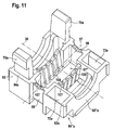
- FIGS. 9 to 11 In a third exemplary embodiment of a cable feedthrough according to the invention, shown in FIGS. 9 to 11, those elements which are identical to those of the preceding exemplary embodiments are provided with the same reference numerals, so that reference is made to the explanations in full.
- the separating surface 14 is not a continuous plane, but only in the region of the holding element surfaces 82a and 84a, but already in the portion 57a of the contact surfaces 56" a, which leads to the web 58, compared to convexly curved by the holding element surfaces 82a and 84a formed plane.
- the parting surface 14 "in the region of the passage body parts 20" a is formed complex and includes with respect to the plane formed by the holding element surfaces 82a and 84a recessed areas, such as the areas 15Z1, 15Z2, 15Z3 and 15Z4, as well as through the support surfaces 82a and 84a formed portions, for example, the areas 15V1, 15V2, 15V3 and 15V4, wherein in assembling two lead body parts 20 "a and 20" b, the projecting portion 15V1 of the one lead body portion 20 "a engages the recessed portion 15Z1 of the other lead body portion 20" b the protruding portion 15V2 of the one penetrating body part 20 "a engages the recessed portion 15Z2 of the other penetrating body member 20" b, the protruding portion 15V3 engages the recessed portion 15Z3 of the other penetrating body member 20 "b, and the protruding portion 15V4 of the one penetrating boss Part of the body 20 "a in the recessed
- the recessed areas 15Z are preferably dimensioned to be smaller than the protruding areas 15V engaging in them, so that even a deformation of the passage body parts 20 "a and 20" b forming elastic material, in particular a compression of the same, must be made, wherein in the area of the abutting surfaces of the recessed areas 15Z and the projecting portions 15V, a high alternating surface pressure arises, whereby a tight seal can be achieved.
- the recessed regions 15Z of the separating surface 14 are formed by recesses 102 formed in the respective bushing body part 20" and the projecting regions 15V of the separating plane 14 "are formed by protrusions 104 of the through body parts 20" rising on either side of a cable cutout 106.
- the holding element parts 64 "a, b are in principle the same as in the second embodiment, shown in Fig. 6. In contrast to the second embodiment, however, are provided in the receptacle 67" preferably arranged in rows 107 support fingers 108 which anchor the respective implementing body part 20 "a, b in the respective retainer member 64" a, as shown in FIG. 11.
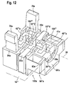
- a fourth exemplary embodiment of a cable feedthrough according to the invention illustrated in the form of one of the two cable feedthrough parts 100, in FIG
- the parting surface 14 "' is also not a plane, but flat in the same manner as in the third embodiment in the area of the retainer surfaces 82a and 84a, while the portion 57a is formed as a convex surface as in the third embodiment.
- each sealing ring segment 41 having projections 104 "', while the other sealing ring segment 43 has recesses 102"' which are also symmetrical to the transverse axis 37 are arranged so that when assembling second passage body parts 20 "'a and 20"' b the projections 104 "' in the sealing ring segment 41a of the one passage body part 20 "'a engage in the recesses 102''of the sealing ring segment 43a of the other passage body part 20"' b and thus additionally improve the seal, wherein the recesses 102 "'have smaller dimensions than the protrusions dipping into these 104 "', so that in the area of the cooperating depressions 102"' and protrusions 104 "', a reinforced surface pressure results which leads to a deformation of the elastic material of the passage body parts 20"' a and 20 "'b in the region of the depressions 102"
- the depressions 102 "'and the projections 104"' likewise form recessed regions 15 "'or protruding regions 15"' of the separating surface 14 "', which thus form a region in the region of the depressions 102"' and projections 104 "' Has complex surface shape.
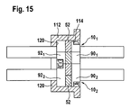
- the cable bushings 10 according to the invention shown in FIGS. 1 to 4 or 5 to 9, as shown in FIGS. 13 to 15, can be connected to cable feedthrough systems 110 at support surfaces 90, 92 and an outer sealing surface 52, which correspond to lateral surfaces of rectangular or square cylinders in cross section in which a plurality of the cable ducts 10 according to the invention are arranged directly adjacent to one another in a frame 112, the individual cable ducts 20, as shown in FIGS. 10 and 11, with their outer sealing surfaces 52 either on an inner surface 114 of the frame 112 or on outer sealing surfaces 52 abut adjacent cable bushings 10 and thus each circumferentially around each cable entry 10 of the invention, a tight seal is formed.
- the conducted cable 24 is also held tightly in the feedthrough body 18, so that overall a sealing of the respective cable 24 with respect to the frame 112 takes place.
- adjacent cable bushings 10 are always arranged so that their parting planes 14 are not aligned with each other, but transverse, preferably perpendicular to each other.
- the cable glands 10 in the frame 112 are preferably such that they form adjacent rows 116, 118, with each of the rows 116, 118 resting on the one hand on the frame 112 and on the other hand on the adjacent row 118, 116.
- the frame 112 is still provided with an undercut 120, wherein each of the rows 116, 118 is supported against such an undercut 120.
- the outer sections 94 are pressed such that the outer sealing surfaces 52 are substantially flush with the support surfaces 90, 92 and, in addition, the cable feedthroughs 10 mutually and on the frame 112 in addition to their Supporting surfaces 90 and 92 abut each other and thus a total of a stable and at least non-positive fixation of the cable glands 10 in the frame 112 takes place.
- a receiving body a plurality of oval or round receptacles for cable penetrations with support surfaces 90, 92 and an outer sealing surface 52, the lateral surfaces of oval or round cylinders in cross section correspond, in each recording a seal by the respective outer sealing surface 52 takes place.
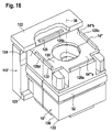
- FIG. 16 In a second exemplary embodiment of a cable feedthrough system according to the invention, illustrated in FIG. 16, those elements which are identical to those of the first exemplary embodiment are provided with the same reference symbols, so that reference can be made to these with regard to the description in full.
- the frame 112 ' is formed so that it has a removable frame cover 122, which is placed on the frame 112 after inserting the plurality of cable glands 10 "according to the third embodiment or 10"' according to the fourth embodiment is, so that one of the undercut 120 opposite further undercut 124 is formed.
- the frame cover 122 is still provided with positioning holes 126, into which one of the positioning projections 128 of the respective cable feedthrough 10 "can engage, whereby the positioning opening 126 enables a non-displaceable positioning of the respective cable feedthrough 10" in the frame 112 '.
- the positioning projections 128c and 128d are still separated by the parting surface 14 'but have the same overall extension, position and dimension as each of the positioning projections 128a and 128b ( Figure 16).
- At least one positioning opening 126 is provided on the frame cover 122 in the frame 112 'for each cable feedthrough to be inserted, so that a secure, reliable and, in particular, immovable fixing of the cable feedthroughs 10 "in the respective frame 112' can be carried out.
- positioning holes 126 are also provided in the portion of the frame 112 'carrying the undercut 120.
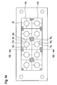
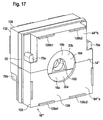
- the cable bushings 10 need not always have the same standard size for a cable feedthrough system according to the invention, but it is conceivable to provide different standard sizes, it being advantageous to With different standard sizes, the successive standard sizes should be dimensioned such that the next largest standard size has twice the edge length.
- Such another standard size of a cable feedthrough is shown in Fig. 17 as a fifth embodiment, wherein on each outer edge two positioning projections 128, for example, the positioning projections 128a1 and 128a2 are provided which have the distance from each other, in the standard size with half the edge length of the positioning projections 128th two immediately adjacent cable glands 10 "have.
- a cable feedthrough 10 "'thus occupies four times the space of, for example, a cable feedthrough 10" in the frame 112' and thus replaces four cable feedthroughs 10 ".
- blind feedthroughs 140 shown in FIG. 18 can also be used in such a cable feedthrough system whose holding element parts 64" a and 64 "b are designed in the same way, as in the third exemplary embodiment.
- these holding element parts 64 "a and 64” b are also provided with sealing elements 12 ", which are formed in principle in the same way as in the third embodiment, but no cable cutout 106, so that a total of the assembly of the sealing element parts 16" a and 16 “b to a dense Completion of the holding element parts 64 "a and 64” b enclosed interior leads and thus can not be filled with such a blind bushing 140 for cable bushings 10 "in the frame 112 'required seats.
- a sixth exemplary embodiment of a cable feedthrough according to the invention, illustrated in FIG. 19, is constructed in the same way as the first exemplary embodiment; however, the sealing element 12 "" is designed so that several, for example three cable feedthrough channels 22 "" a, 22 "" b and 22 "" c arranged side by side.
- the sealing element 12 "" is still composed of two sealing element parts 16 “" a and 16 “” b, wherein the sealing element parts are also in turn held together by holding elements 60 “" and 62 “” which also by the parting plane 14 in holding element parts 64th "" a and 64 "” b and 66 "" a and 66 "” b are split.
- the cable ducts also form with non-round cross-sectional shapes and thus also in cross section, for example, oval, rectangular or flat cable to perform and obtain a tight seal with this.
- the sixth embodiment of the grommet according to the invention is constructed of elements which are identical to those of the first or second embodiment, so that with respect to the description of the same fully incorporated by reference to the first or second embodiment.
- the sixth exemplary embodiment of the cable feedthrough 10 "" according to the invention can likewise be inserted into the frame 112 with a plurality of the cable feedthroughs 10 and / or 10 ", wherein preferably the outer dimensions in the area of the supporting surfaces 90" "and 92" "are selected such that the second embodiment of the cable gland 10 "" requires the same space as two cable glands 10 of the first embodiment, so that in the same way a combination with the cable glands 10 of the first embodiment is possible.
Landscapes
- Engineering & Computer Science (AREA)
- Architecture (AREA)
- Civil Engineering (AREA)
- Structural Engineering (AREA)
- Installation Of Indoor Wiring (AREA)
- Cable Accessories (AREA)
Priority Applications (1)
| Application Number | Priority Date | Filing Date | Title |
|---|---|---|---|
| EP10173405.1A EP2249448B1 (fr) | 2005-04-08 | 2006-03-29 | Passe-câble |
Applications Claiming Priority (1)
| Application Number | Priority Date | Filing Date | Title |
|---|---|---|---|
| DE102005017689A DE102005017689A1 (de) | 2005-04-08 | 2005-04-08 | Kabeldurchführung und Kabeldurchführungssystem |
Related Child Applications (2)
| Application Number | Title | Priority Date | Filing Date |
|---|---|---|---|
| EP10173405.1A Division EP2249448B1 (fr) | 2005-04-08 | 2006-03-29 | Passe-câble |
| EP10173405.1A Division-Into EP2249448B1 (fr) | 2005-04-08 | 2006-03-29 | Passe-câble |
Publications (3)
| Publication Number | Publication Date |
|---|---|
| EP1710882A2 true EP1710882A2 (fr) | 2006-10-11 |
| EP1710882A3 EP1710882A3 (fr) | 2007-06-27 |
| EP1710882B1 EP1710882B1 (fr) | 2017-01-11 |
Family
ID=36644528
Family Applications (2)
| Application Number | Title | Priority Date | Filing Date |
|---|---|---|---|
| EP10173405.1A Expired - Lifetime EP2249448B1 (fr) | 2005-04-08 | 2006-03-29 | Passe-câble |
| EP06006501.8A Expired - Lifetime EP1710882B1 (fr) | 2005-04-08 | 2006-03-29 | Dispositif pour traversée de câble et système pour traversée de câble |
Family Applications Before (1)
| Application Number | Title | Priority Date | Filing Date |
|---|---|---|---|
| EP10173405.1A Expired - Lifetime EP2249448B1 (fr) | 2005-04-08 | 2006-03-29 | Passe-câble |
Country Status (2)
| Country | Link |
|---|---|
| EP (2) | EP2249448B1 (fr) |
| DE (1) | DE102005017689A1 (fr) |
Cited By (23)
| Publication number | Priority date | Publication date | Assignee | Title |
|---|---|---|---|---|
| WO2007059884A1 (fr) | 2005-11-25 | 2007-05-31 | Rittal Gmbh & Co. Kg | Dispositif pour faire cheminer des cables ou des lignes |
| WO2012062497A1 (fr) * | 2010-11-08 | 2012-05-18 | Robert Bosch Gmbh | Dispositif de fixation pour une ligne et procédé de fixation d'une ligne |
| WO2014005916A3 (fr) * | 2012-07-02 | 2014-03-27 | Tyco Electronics Raychem Bvba | Unité d'étanchéification de câble comportant plusieurs modules d'étanchéité |
| EP2866322A1 (fr) | 2013-10-27 | 2015-04-29 | Lapp Engineering & Co. | Dispositif de passage de câbles |
| EP2916409A3 (fr) * | 2014-03-03 | 2015-12-23 | Murrelektronik GmbH | Cadre pour passe-câble, éléments de fixation et système de passe-câble |
| DE202015106975U1 (de) | 2015-12-21 | 2016-05-04 | Lapp Engineering & Co. | Kabeldurchführungsvorrichtung |
| US9400363B2 (en) | 2012-07-02 | 2016-07-26 | CommScope Connectivity Belgium BVBA | Pressure actuated sealant assembly |
| WO2016177364A1 (fr) * | 2015-05-05 | 2016-11-10 | Conta-Clip Verbindungstechnik Gmbh | Ensemble comprenant une traversée murale pour plusieurs câbles ainsi que procédé de fabrication et kit |
| US9502878B2 (en) | 2012-07-02 | 2016-11-22 | CommScope Connectivity Belgium BVBA | Re-enterable enclosure |
| EP3033813A4 (fr) * | 2013-08-13 | 2017-03-22 | Specified Technologies, Inc. | Conduit de protection pour une ouverture dans un panneau structural |
| US9753237B2 (en) | 2012-07-02 | 2017-09-05 | CommScope Connectivity Belgium BVBA | Seal actuator with actuation level indicator |
| US9768604B2 (en) | 2009-12-03 | 2017-09-19 | CommScope Connectivity Belgium BVBA | Gel sealing device |
| US9944239B1 (en) | 2017-05-19 | 2018-04-17 | Newfrey Llc | Fluid and dust resistant split grommet |
| DE202013012703U1 (de) | 2013-10-27 | 2018-09-10 | Lapp Engineering & Co. | Kabeldurchführungsvorrichtung |
| EP3417520A1 (fr) * | 2016-02-16 | 2018-12-26 | Reichle & De-Massari AG | Dispositif de boîte de jonction, système modulaire pour réaliser une boîte de jonction et procédé de réalisation d'une boîte de jonction à partir d'un système modulaire |
| EP3779545A4 (fr) * | 2019-06-13 | 2021-02-17 | Huawei Technologies Co., Ltd. | Structure de fixation de câble optique et dispositif de connexion de câble optique |
| DE102019125758A1 (de) * | 2019-09-25 | 2021-03-25 | Connect Com GmbH | Dichtungsvorrichtung mit einem harten Dichtkörper |
| DE102019125761A1 (de) * | 2019-09-25 | 2021-03-25 | Connect Com GmbH | Dichtungsvorrichtung mit einer Feder in einem Verteilergehäuse |
| DE102019125760A1 (de) * | 2019-09-25 | 2021-03-25 | Connect Com GmbH | Dichtungsvorrichtung mit einem Dichtkörper mit Verengungskontur |
| WO2021058064A1 (fr) * | 2019-09-25 | 2021-04-01 | Conta-Clip Verbindungstechnik Gesellschaft mit beschränkter Haftung | Élément rapporté et kit pour traversée de câble pour parois |
| EP3829005A4 (fr) * | 2018-12-28 | 2022-03-09 | Foshan Welling Washer Motor Manufacturing Co., Ltd. | Module de manchon et dispositif comportant des fils de sortie |
| EP4112967A1 (fr) * | 2021-06-28 | 2023-01-04 | Nexans | Amortisseur de vibrations |
| CN120767748A (zh) * | 2025-06-07 | 2025-10-10 | 浙江海默机械工业有限公司 | 一种线缆密封模块系统 |
Families Citing this family (6)
| Publication number | Priority date | Publication date | Assignee | Title |
|---|---|---|---|---|
| DE102007012187B4 (de) * | 2007-03-14 | 2016-06-09 | Pflitsch Gmbh & Co. Kg | Vorrichtung zur Durchführung von Kabeln |
| DE102010037463A1 (de) * | 2010-09-10 | 2012-03-15 | Phoenix Contact Gmbh & Co. Kg | Rahmen eines Kabeleinführungssystems und Kabeltülle hierfür |
| EP3139719B1 (fr) | 2015-09-07 | 2020-02-26 | Lapp Engineering & Co. | Dispositif de mise en contact pour passe-cables et passe-cable |
| LU93242B1 (de) * | 2016-09-29 | 2018-04-11 | Phoenix Contact Gmbh & Co Kg Intellectual Property Licenses & Standards | Kabelhaltevorrichtung |
| DE102017212009A1 (de) * | 2017-07-13 | 2019-03-07 | Icotek Project Gmbh & Co. Kg | Zugentlastungstülle |
| EP4325676A1 (fr) | 2022-08-19 | 2024-02-21 | Lapp Engineering AG | Dispositif de passage de câble |
Citations (3)
| Publication number | Priority date | Publication date | Assignee | Title |
|---|---|---|---|---|
| US5545854A (en) | 1993-12-29 | 1996-08-13 | Yazaki Corporation | Grommet for wire sealing |
| WO1999056368A1 (fr) | 1998-04-29 | 1999-11-04 | Nokia Networks Oy | Module pour systeme modulaire d'entree de cable |
| DE10140714A1 (de) | 2001-08-24 | 2003-03-13 | Woco Franz Josef Wolf & Co Gmbh | Tülle |
Family Cites Families (4)
| Publication number | Priority date | Publication date | Assignee | Title |
|---|---|---|---|---|
| AR204293A1 (es) * | 1975-04-11 | 1975-12-10 | Siemens Ag | Caja de cable termoplastico con elemento de obturacion |
| DE19721659B4 (de) * | 1997-05-23 | 2005-10-20 | Murrplastik Systemtechnik Gmbh | Anordnung zum Führen von Kabeln oder Leitungen |
| DE19817279A1 (de) * | 1998-04-18 | 1999-10-21 | Volkswagen Ag | Leitungsdurchführung |
| DE10046157A1 (de) * | 2000-09-15 | 2002-03-28 | Murrplastik Systemtechnik Gmbh | Tülle |
-
2005
- 2005-04-08 DE DE102005017689A patent/DE102005017689A1/de not_active Ceased
-
2006
- 2006-03-29 EP EP10173405.1A patent/EP2249448B1/fr not_active Expired - Lifetime
- 2006-03-29 EP EP06006501.8A patent/EP1710882B1/fr not_active Expired - Lifetime
Patent Citations (3)
| Publication number | Priority date | Publication date | Assignee | Title |
|---|---|---|---|---|
| US5545854A (en) | 1993-12-29 | 1996-08-13 | Yazaki Corporation | Grommet for wire sealing |
| WO1999056368A1 (fr) | 1998-04-29 | 1999-11-04 | Nokia Networks Oy | Module pour systeme modulaire d'entree de cable |
| DE10140714A1 (de) | 2001-08-24 | 2003-03-13 | Woco Franz Josef Wolf & Co Gmbh | Tülle |
Cited By (51)
| Publication number | Priority date | Publication date | Assignee | Title |
|---|---|---|---|---|
| CN101175938B (zh) * | 2005-11-25 | 2011-09-21 | 利塔尔两合公司 | 用于引导电缆或导线的设备 |
| US8093513B2 (en) | 2005-11-25 | 2012-01-10 | Rittal Gmbh & Co. Kg | Device for guiding cables or wires |
| WO2007059884A1 (fr) | 2005-11-25 | 2007-05-31 | Rittal Gmbh & Co. Kg | Dispositif pour faire cheminer des cables ou des lignes |
| US10910810B2 (en) | 2009-12-03 | 2021-02-02 | CommScope Connectivity Belgium BVBA | Gel sealing device |
| US9768604B2 (en) | 2009-12-03 | 2017-09-19 | CommScope Connectivity Belgium BVBA | Gel sealing device |
| US10298003B2 (en) | 2009-12-03 | 2019-05-21 | CommScope Connectivity Belgium BVBA | Gel sealing device |
| US11784480B2 (en) | 2009-12-03 | 2023-10-10 | CommScope Connectivity Belgium BVBA | Gel sealing device |
| CN103180177B (zh) * | 2010-11-08 | 2016-08-17 | 罗伯特·博世有限公司 | 用于导线的固定装置以及用于固定导线的方法 |
| WO2012062497A1 (fr) * | 2010-11-08 | 2012-05-18 | Robert Bosch Gmbh | Dispositif de fixation pour une ligne et procédé de fixation d'une ligne |
| CN103180177A (zh) * | 2010-11-08 | 2013-06-26 | 罗伯特·博世有限公司 | 用于导线的固定装置以及用于固定导线的方法 |
| US11658471B2 (en) | 2012-07-02 | 2023-05-23 | CommScope Connectivity Belgium BVBA | Cable sealing unit with multiple sealing modules |
| DE202013012190U1 (de) | 2012-07-02 | 2015-10-16 | Tyco Electronics Raychem Bvba | Kabelabdichtungseinheit mit mehreren Abdichtungsmodulen |
| US11973329B2 (en) | 2012-07-02 | 2024-04-30 | CommScope Connectivity Belgium BVBA | Cable sealing unit with multiple sealing modules |
| US9502878B2 (en) | 2012-07-02 | 2016-11-22 | CommScope Connectivity Belgium BVBA | Re-enterable enclosure |
| US10393978B2 (en) | 2012-07-02 | 2019-08-27 | CommScope Connectivity Belgium BVBA | Seal actuator with actuation level indicator |
| US9632268B2 (en) | 2012-07-02 | 2017-04-25 | CommScope Connectivity Belgium BVBA | Pressure actuated sealant assembly |
| US9685776B2 (en) | 2012-07-02 | 2017-06-20 | CommScope Connectivity Belgium BVBA | Cable sealing unit with multiple sealing modules |
| US10951017B2 (en) | 2012-07-02 | 2021-03-16 | CommScope Connectivity Belgium BVBA | Cable sealing unit with multiple sealing modules |
| US9753237B2 (en) | 2012-07-02 | 2017-09-05 | CommScope Connectivity Belgium BVBA | Seal actuator with actuation level indicator |
| US9400363B2 (en) | 2012-07-02 | 2016-07-26 | CommScope Connectivity Belgium BVBA | Pressure actuated sealant assembly |
| US12218493B2 (en) | 2012-07-02 | 2025-02-04 | CommScope Connectivity Belgium BVBA | Cable sealing unit with multiple sealing modules |
| US10680426B2 (en) | 2012-07-02 | 2020-06-09 | CommScope Connectivity Belgium BVBA | Cable sealing unit with multiple sealing modules |
| US9948082B2 (en) | 2012-07-02 | 2018-04-17 | CommScope Connectivity Belgium BVBA | Cable sealing unit with multiple sealing modules |
| WO2014005916A3 (fr) * | 2012-07-02 | 2014-03-27 | Tyco Electronics Raychem Bvba | Unité d'étanchéification de câble comportant plusieurs modules d'étanchéité |
| US10084302B2 (en) | 2012-07-02 | 2018-09-25 | CommScope Connectivity Belgium BVBA | Re-enterable enclosure |
| US10411455B2 (en) | 2012-07-02 | 2019-09-10 | CommScope Connectivity Belgium BVBA | Re-enterable enclosure |
| EP3033813A4 (fr) * | 2013-08-13 | 2017-03-22 | Specified Technologies, Inc. | Conduit de protection pour une ouverture dans un panneau structural |
| DE202013012703U1 (de) | 2013-10-27 | 2018-09-10 | Lapp Engineering & Co. | Kabeldurchführungsvorrichtung |
| EP2866322A1 (fr) | 2013-10-27 | 2015-04-29 | Lapp Engineering & Co. | Dispositif de passage de câbles |
| EP2916409A3 (fr) * | 2014-03-03 | 2015-12-23 | Murrelektronik GmbH | Cadre pour passe-câble, éléments de fixation et système de passe-câble |
| EP3292604B1 (fr) * | 2015-05-05 | 2021-08-25 | CONTA-CLIP Verbindungstechnik GmbH | Procédé de réalisation d'une traversée mural pour plusieurs câbles et ensemble |
| CN107592951B (zh) * | 2015-05-05 | 2020-05-01 | 孔塔-科力普连接技术有限公司 | 用于制造针对多个线缆的壁穿引件的方法以及系统 |
| WO2016177364A1 (fr) * | 2015-05-05 | 2016-11-10 | Conta-Clip Verbindungstechnik Gmbh | Ensemble comprenant une traversée murale pour plusieurs câbles ainsi que procédé de fabrication et kit |
| CN107592951A (zh) * | 2015-05-05 | 2018-01-16 | 孔塔-科力普连接技术有限公司 | 带有用于多个线缆的壁穿引件的系统和制造方法以及成套结构组件 |
| US10298001B2 (en) | 2015-05-05 | 2019-05-21 | Conta-Clip Verbindungstechnik Gmbh | Method for the production of a wall lead-through for several cables as well as arrangement |
| DE202015106975U1 (de) | 2015-12-21 | 2016-05-04 | Lapp Engineering & Co. | Kabeldurchführungsvorrichtung |
| EP3185379A1 (fr) | 2015-12-21 | 2017-06-28 | Lapp Engineering & Co. | Dispositif de passage de câble |
| EP3417520A1 (fr) * | 2016-02-16 | 2018-12-26 | Reichle & De-Massari AG | Dispositif de boîte de jonction, système modulaire pour réaliser une boîte de jonction et procédé de réalisation d'une boîte de jonction à partir d'un système modulaire |
| US9944239B1 (en) | 2017-05-19 | 2018-04-17 | Newfrey Llc | Fluid and dust resistant split grommet |
| KR20230030027A (ko) * | 2018-12-28 | 2023-03-03 | 포산 웰링 워셔 모터 매뉴팩처링 컴퍼니 리미티드 | 부싱 모듈 및 리드선을 구비하는 장치 |
| EP3829005A4 (fr) * | 2018-12-28 | 2022-03-09 | Foshan Welling Washer Motor Manufacturing Co., Ltd. | Module de manchon et dispositif comportant des fils de sortie |
| EP3779545A4 (fr) * | 2019-06-13 | 2021-02-17 | Huawei Technologies Co., Ltd. | Structure de fixation de câble optique et dispositif de connexion de câble optique |
| WO2021058064A1 (fr) * | 2019-09-25 | 2021-04-01 | Conta-Clip Verbindungstechnik Gesellschaft mit beschränkter Haftung | Élément rapporté et kit pour traversée de câble pour parois |
| DE102019125760A1 (de) * | 2019-09-25 | 2021-03-25 | Connect Com GmbH | Dichtungsvorrichtung mit einem Dichtkörper mit Verengungskontur |
| DE102019125761A1 (de) * | 2019-09-25 | 2021-03-25 | Connect Com GmbH | Dichtungsvorrichtung mit einer Feder in einem Verteilergehäuse |
| US12176696B2 (en) | 2019-09-25 | 2024-12-24 | Conta-Clip Verbindungstechnik Gmbh | Insertion component and kit for a cable passage for walls |
| DE102019125758A1 (de) * | 2019-09-25 | 2021-03-25 | Connect Com GmbH | Dichtungsvorrichtung mit einem harten Dichtkörper |
| US20230020124A1 (en) * | 2021-06-28 | 2023-01-19 | Nexans | Vibration damper |
| EP4112967A1 (fr) * | 2021-06-28 | 2023-01-04 | Nexans | Amortisseur de vibrations |
| US12025203B2 (en) * | 2021-06-28 | 2024-07-02 | Nexans | Vibration damper |
| CN120767748A (zh) * | 2025-06-07 | 2025-10-10 | 浙江海默机械工业有限公司 | 一种线缆密封模块系统 |
Also Published As
| Publication number | Publication date |
|---|---|
| EP2249448B1 (fr) | 2021-09-01 |
| DE102005017689A1 (de) | 2006-10-12 |
| EP2249448A2 (fr) | 2010-11-10 |
| EP2249448A3 (fr) | 2016-03-23 |
| EP1710882A3 (fr) | 2007-06-27 |
| EP1710882B1 (fr) | 2017-01-11 |
Similar Documents
| Publication | Publication Date | Title |
|---|---|---|
| EP1710882B1 (fr) | Dispositif pour traversée de câble et système pour traversée de câble | |
| DE3512165C2 (fr) | ||
| EP3292604B1 (fr) | Procédé de réalisation d'une traversée mural pour plusieurs câbles et ensemble | |
| DE3512175C2 (fr) | ||
| DE69707645T2 (de) | Verschluss für kabel | |
| DE69215269T2 (de) | Kabelverschlussvorrichtung mit einer verbesserten Dichtungsbuchse | |
| DE4004211C2 (de) | Elektrischer Rauschabsorber | |
| EP3517816A1 (fr) | Insert d'étanchéité | |
| DE102008022055A1 (de) | Anschlussdose für ein Solarmodul | |
| DE102018207019A1 (de) | Wanddurchführung | |
| EP2614565B1 (fr) | Traversée de câbles | |
| WO2021170175A1 (fr) | Dispositif d'entrée de câble pour armoire de commande, son agencement et son procédé de fonctionnement | |
| EP0263430B1 (fr) | Toit pare-soleil | |
| DE19912917A1 (de) | Elektrischer Rauschabsorber und Verfahren zu seiner Montage an einem Kabel | |
| EP4542801A2 (fr) | Passage de câble pour le passage de câbles à travers un élément de séparation et ensemble | |
| EP1503471B1 (fr) | Plaque de traversée de câble | |
| EP3819138B1 (fr) | Unité d'installation | |
| AT1268U1 (de) | Sichtfenster | |
| EP3483996A1 (fr) | Dispositif pour un passe-câble | |
| DE102019206287B4 (de) | Verschließvorrichtung | |
| EP3120456B1 (fr) | Dispositif pour absorber le bruit électrique de câbles | |
| DE102013201149A1 (de) | Kabeldurchführungseinrichtung | |
| DE19907204A1 (de) | Dichtelement | |
| DE10010452A1 (de) | Dichtungskörper für längsgeteilte Kabelgarnituren | |
| EP0435075B1 (fr) | Manchon élastique |
Legal Events
| Date | Code | Title | Description |
|---|---|---|---|
| PUAI | Public reference made under article 153(3) epc to a published international application that has entered the european phase |
Free format text: ORIGINAL CODE: 0009012 |
|
| AK | Designated contracting states |
Kind code of ref document: A2 Designated state(s): AT BE BG CH CY CZ DE DK EE ES FI FR GB GR HU IE IS IT LI LT LU LV MC NL PL PT RO SE SI SK TR |
|
| AX | Request for extension of the european patent |
Extension state: AL BA HR MK YU |
|
| PUAL | Search report despatched |
Free format text: ORIGINAL CODE: 0009013 |
|
| AK | Designated contracting states |
Kind code of ref document: A3 Designated state(s): AT BE BG CH CY CZ DE DK EE ES FI FR GB GR HU IE IS IT LI LT LU LV MC NL PL PT RO SE SI SK TR |
|
| AX | Request for extension of the european patent |
Extension state: AL BA HR MK YU |
|
| 17P | Request for examination filed |
Effective date: 20070913 |
|
| 17Q | First examination report despatched |
Effective date: 20071022 |
|
| AKX | Designation fees paid |
Designated state(s): AT BE BG CH CY CZ DE DK EE ES FI FR GB GR HU IE IS IT LI LT LU LV MC NL PL PT RO SE SI SK TR |
|
| GRAP | Despatch of communication of intention to grant a patent |
Free format text: ORIGINAL CODE: EPIDOSNIGR1 |
|
| INTG | Intention to grant announced |
Effective date: 20160803 |
|
| RAP1 | Party data changed (applicant data changed or rights of an application transferred) |
Owner name: LAPP ENGINEERING & CO. |
|
| STAA | Information on the status of an ep patent application or granted ep patent |
Free format text: STATUS: GRANT OF PATENT IS INTENDED |
|
| GRAS | Grant fee paid |
Free format text: ORIGINAL CODE: EPIDOSNIGR3 |
|
| GRAA | (expected) grant |
Free format text: ORIGINAL CODE: 0009210 |
|
| STAA | Information on the status of an ep patent application or granted ep patent |
Free format text: STATUS: THE PATENT HAS BEEN GRANTED |
|
| AK | Designated contracting states |
Kind code of ref document: B1 Designated state(s): AT BE BG CH CY CZ DE DK EE ES FI FR GB GR HU IE IS IT LI LT LU LV MC NL PL PT RO SE SI SK TR |
|
| REG | Reference to a national code |
Ref country code: GB Ref legal event code: FG4D Free format text: NOT ENGLISH |
|
| REG | Reference to a national code |
Ref country code: CH Ref legal event code: EP |
|
| REG | Reference to a national code |
Ref country code: AT Ref legal event code: REF Ref document number: 862085 Country of ref document: AT Kind code of ref document: T Effective date: 20170115 |
|
| REG | Reference to a national code |
Ref country code: IE Ref legal event code: FG4D Free format text: LANGUAGE OF EP DOCUMENT: GERMAN |
|
| REG | Reference to a national code |
Ref country code: DE Ref legal event code: R096 Ref document number: 502006015324 Country of ref document: DE |
|
| REG | Reference to a national code |
Ref country code: SE Ref legal event code: TRGR |
|
| REG | Reference to a national code |
Ref country code: FR Ref legal event code: PLFP Year of fee payment: 12 |
|
| REG | Reference to a national code |
Ref country code: LT Ref legal event code: MG4D |
|
| REG | Reference to a national code |
Ref country code: NL Ref legal event code: MP Effective date: 20170111 |
|
| PG25 | Lapsed in a contracting state [announced via postgrant information from national office to epo] |
Ref country code: NL Free format text: LAPSE BECAUSE OF FAILURE TO SUBMIT A TRANSLATION OF THE DESCRIPTION OR TO PAY THE FEE WITHIN THE PRESCRIBED TIME-LIMIT Effective date: 20170111 |
|
| PG25 | Lapsed in a contracting state [announced via postgrant information from national office to epo] |
Ref country code: FI Free format text: LAPSE BECAUSE OF FAILURE TO SUBMIT A TRANSLATION OF THE DESCRIPTION OR TO PAY THE FEE WITHIN THE PRESCRIBED TIME-LIMIT Effective date: 20170111 Ref country code: IS Free format text: LAPSE BECAUSE OF FAILURE TO SUBMIT A TRANSLATION OF THE DESCRIPTION OR TO PAY THE FEE WITHIN THE PRESCRIBED TIME-LIMIT Effective date: 20170511 Ref country code: LT Free format text: LAPSE BECAUSE OF FAILURE TO SUBMIT A TRANSLATION OF THE DESCRIPTION OR TO PAY THE FEE WITHIN THE PRESCRIBED TIME-LIMIT Effective date: 20170111 Ref country code: GR Free format text: LAPSE BECAUSE OF FAILURE TO SUBMIT A TRANSLATION OF THE DESCRIPTION OR TO PAY THE FEE WITHIN THE PRESCRIBED TIME-LIMIT Effective date: 20170412 |
|
| PG25 | Lapsed in a contracting state [announced via postgrant information from national office to epo] |
Ref country code: ES Free format text: LAPSE BECAUSE OF FAILURE TO SUBMIT A TRANSLATION OF THE DESCRIPTION OR TO PAY THE FEE WITHIN THE PRESCRIBED TIME-LIMIT Effective date: 20170111 Ref country code: PT Free format text: LAPSE BECAUSE OF FAILURE TO SUBMIT A TRANSLATION OF THE DESCRIPTION OR TO PAY THE FEE WITHIN THE PRESCRIBED TIME-LIMIT Effective date: 20170511 Ref country code: PL Free format text: LAPSE BECAUSE OF FAILURE TO SUBMIT A TRANSLATION OF THE DESCRIPTION OR TO PAY THE FEE WITHIN THE PRESCRIBED TIME-LIMIT Effective date: 20170111 Ref country code: LV Free format text: LAPSE BECAUSE OF FAILURE TO SUBMIT A TRANSLATION OF THE DESCRIPTION OR TO PAY THE FEE WITHIN THE PRESCRIBED TIME-LIMIT Effective date: 20170111 Ref country code: BG Free format text: LAPSE BECAUSE OF FAILURE TO SUBMIT A TRANSLATION OF THE DESCRIPTION OR TO PAY THE FEE WITHIN THE PRESCRIBED TIME-LIMIT Effective date: 20170411 |
|
| REG | Reference to a national code |
Ref country code: DE Ref legal event code: R097 Ref document number: 502006015324 Country of ref document: DE |
|
| PG25 | Lapsed in a contracting state [announced via postgrant information from national office to epo] |
Ref country code: SK Free format text: LAPSE BECAUSE OF FAILURE TO SUBMIT A TRANSLATION OF THE DESCRIPTION OR TO PAY THE FEE WITHIN THE PRESCRIBED TIME-LIMIT Effective date: 20170111 Ref country code: CZ Free format text: LAPSE BECAUSE OF FAILURE TO SUBMIT A TRANSLATION OF THE DESCRIPTION OR TO PAY THE FEE WITHIN THE PRESCRIBED TIME-LIMIT Effective date: 20170111 Ref country code: RO Free format text: LAPSE BECAUSE OF FAILURE TO SUBMIT A TRANSLATION OF THE DESCRIPTION OR TO PAY THE FEE WITHIN THE PRESCRIBED TIME-LIMIT Effective date: 20170111 Ref country code: EE Free format text: LAPSE BECAUSE OF FAILURE TO SUBMIT A TRANSLATION OF THE DESCRIPTION OR TO PAY THE FEE WITHIN THE PRESCRIBED TIME-LIMIT Effective date: 20170111 |
|
| PLBE | No opposition filed within time limit |
Free format text: ORIGINAL CODE: 0009261 |
|
| STAA | Information on the status of an ep patent application or granted ep patent |
Free format text: STATUS: NO OPPOSITION FILED WITHIN TIME LIMIT |
|
| PG25 | Lapsed in a contracting state [announced via postgrant information from national office to epo] |
Ref country code: DK Free format text: LAPSE BECAUSE OF FAILURE TO SUBMIT A TRANSLATION OF THE DESCRIPTION OR TO PAY THE FEE WITHIN THE PRESCRIBED TIME-LIMIT Effective date: 20170111 Ref country code: MC Free format text: LAPSE BECAUSE OF FAILURE TO SUBMIT A TRANSLATION OF THE DESCRIPTION OR TO PAY THE FEE WITHIN THE PRESCRIBED TIME-LIMIT Effective date: 20170111 |
|
| 26N | No opposition filed |
Effective date: 20171012 |
|
| REG | Reference to a national code |
Ref country code: IE Ref legal event code: MM4A |
|
| PG25 | Lapsed in a contracting state [announced via postgrant information from national office to epo] |
Ref country code: LU Free format text: LAPSE BECAUSE OF NON-PAYMENT OF DUE FEES Effective date: 20170329 |
|
| PG25 | Lapsed in a contracting state [announced via postgrant information from national office to epo] |
Ref country code: IE Free format text: LAPSE BECAUSE OF NON-PAYMENT OF DUE FEES Effective date: 20170329 Ref country code: SI Free format text: LAPSE BECAUSE OF FAILURE TO SUBMIT A TRANSLATION OF THE DESCRIPTION OR TO PAY THE FEE WITHIN THE PRESCRIBED TIME-LIMIT Effective date: 20170111 |
|
| REG | Reference to a national code |
Ref country code: BE Ref legal event code: MM Effective date: 20170331 |
|
| REG | Reference to a national code |
Ref country code: FR Ref legal event code: PLFP Year of fee payment: 13 |
|
| PG25 | Lapsed in a contracting state [announced via postgrant information from national office to epo] |
Ref country code: BE Free format text: LAPSE BECAUSE OF NON-PAYMENT OF DUE FEES Effective date: 20170331 |
|
| PG25 | Lapsed in a contracting state [announced via postgrant information from national office to epo] |
Ref country code: HU Free format text: LAPSE BECAUSE OF FAILURE TO SUBMIT A TRANSLATION OF THE DESCRIPTION OR TO PAY THE FEE WITHIN THE PRESCRIBED TIME-LIMIT; INVALID AB INITIO Effective date: 20060329 |
|
| PG25 | Lapsed in a contracting state [announced via postgrant information from national office to epo] |
Ref country code: CY Free format text: LAPSE BECAUSE OF NON-PAYMENT OF DUE FEES Effective date: 20170111 |
|
| REG | Reference to a national code |
Ref country code: AT Ref legal event code: MM01 Ref document number: 862085 Country of ref document: AT Kind code of ref document: T Effective date: 20200329 |
|
| PG25 | Lapsed in a contracting state [announced via postgrant information from national office to epo] |
Ref country code: AT Free format text: LAPSE BECAUSE OF NON-PAYMENT OF DUE FEES Effective date: 20200329 |
|
| P01 | Opt-out of the competence of the unified patent court (upc) registered |
Effective date: 20230517 |
|
| REG | Reference to a national code |
Ref country code: DE Ref legal event code: R082 Ref document number: 502006015324 Country of ref document: DE Representative=s name: WUESTHOFF & WUESTHOFF PATENTANWAELTE UND RECHT, DE Ref country code: DE Ref legal event code: R082 Ref document number: 502006015324 Country of ref document: DE Representative=s name: WUESTHOFF & WUESTHOFF, PATENTANWAELTE PARTG MB, DE |
|
| PGFP | Annual fee paid to national office [announced via postgrant information from national office to epo] |
Ref country code: SE Payment date: 20250321 Year of fee payment: 20 |
|
| PGFP | Annual fee paid to national office [announced via postgrant information from national office to epo] |
Ref country code: DE Payment date: 20250319 Year of fee payment: 20 |
|
| PGFP | Annual fee paid to national office [announced via postgrant information from national office to epo] |
Ref country code: FR Payment date: 20250325 Year of fee payment: 20 |
|
| PGFP | Annual fee paid to national office [announced via postgrant information from national office to epo] |
Ref country code: IT Payment date: 20250325 Year of fee payment: 20 Ref country code: GB Payment date: 20250321 Year of fee payment: 20 |
|
| PGFP | Annual fee paid to national office [announced via postgrant information from national office to epo] |
Ref country code: TR Payment date: 20250324 Year of fee payment: 20 |
|
| PGFP | Annual fee paid to national office [announced via postgrant information from national office to epo] |
Ref country code: CH Payment date: 20250401 Year of fee payment: 20 |