EP1711036A1 - Miroir chauffable pour un espace d'habitation - Google Patents
Miroir chauffable pour un espace d'habitation Download PDFInfo
- Publication number
- EP1711036A1 EP1711036A1 EP06007349A EP06007349A EP1711036A1 EP 1711036 A1 EP1711036 A1 EP 1711036A1 EP 06007349 A EP06007349 A EP 06007349A EP 06007349 A EP06007349 A EP 06007349A EP 1711036 A1 EP1711036 A1 EP 1711036A1
- Authority
- EP
- European Patent Office
- Prior art keywords
- mirror
- cage
- heated
- heated mirror
- resistance heater
- Prior art date
- Legal status (The legal status is an assumption and is not a legal conclusion. Google has not performed a legal analysis and makes no representation as to the accuracy of the status listed.)
- Withdrawn
Links
- 238000010438 heat treatment Methods 0.000 claims abstract description 30
- 125000006850 spacer group Chemical group 0.000 claims abstract description 3
- 238000002310 reflectometry Methods 0.000 claims description 7
- 230000005855 radiation Effects 0.000 claims description 6
- 230000001105 regulatory effect Effects 0.000 claims description 4
- 230000001276 controlling effect Effects 0.000 claims description 2
- 238000013021 overheating Methods 0.000 claims description 2
- 230000001681 protective effect Effects 0.000 claims description 2
- 230000002441 reversible effect Effects 0.000 claims description 2
- 238000006073 displacement reaction Methods 0.000 claims 1
- XLYOFNOQVPJJNP-UHFFFAOYSA-N water Substances O XLYOFNOQVPJJNP-UHFFFAOYSA-N 0.000 claims 1
- 239000012080 ambient air Substances 0.000 description 5
- 206010014357 Electric shock Diseases 0.000 description 4
- 238000011161 development Methods 0.000 description 4
- 230000018109 developmental process Effects 0.000 description 4
- 230000008901 benefit Effects 0.000 description 3
- 238000009833 condensation Methods 0.000 description 3
- 230000005494 condensation Effects 0.000 description 3
- 239000003570 air Substances 0.000 description 2
- 239000011248 coating agent Substances 0.000 description 2
- 238000000576 coating method Methods 0.000 description 2
- 238000002485 combustion reaction Methods 0.000 description 2
- 239000011521 glass Substances 0.000 description 2
- 230000017525 heat dissipation Effects 0.000 description 2
- 238000009413 insulation Methods 0.000 description 2
- 206010014405 Electrocution Diseases 0.000 description 1
- 229910052782 aluminium Inorganic materials 0.000 description 1
- XAGFODPZIPBFFR-UHFFFAOYSA-N aluminium Chemical compound [Al] XAGFODPZIPBFFR-UHFFFAOYSA-N 0.000 description 1
- 230000004888 barrier function Effects 0.000 description 1
- 238000003287 bathing Methods 0.000 description 1
- 230000033228 biological regulation Effects 0.000 description 1
- 230000005540 biological transmission Effects 0.000 description 1
- 230000000295 complement effect Effects 0.000 description 1
- 230000001419 dependent effect Effects 0.000 description 1
- 230000000694 effects Effects 0.000 description 1
- 229910052751 metal Inorganic materials 0.000 description 1
- 239000002184 metal Substances 0.000 description 1
- 150000002739 metals Chemical class 0.000 description 1
- 230000003287 optical effect Effects 0.000 description 1
- 238000001556 precipitation Methods 0.000 description 1
- 239000004065 semiconductor Substances 0.000 description 1
- 229910052710 silicon Inorganic materials 0.000 description 1
- 239000010703 silicon Substances 0.000 description 1
- 238000010025 steaming Methods 0.000 description 1
- 238000007740 vapor deposition Methods 0.000 description 1
Images
Classifications
-
- H—ELECTRICITY
- H05—ELECTRIC TECHNIQUES NOT OTHERWISE PROVIDED FOR
- H05B—ELECTRIC HEATING; ELECTRIC LIGHT SOURCES NOT OTHERWISE PROVIDED FOR; CIRCUIT ARRANGEMENTS FOR ELECTRIC LIGHT SOURCES, IN GENERAL
- H05B3/00—Ohmic-resistance heating
- H05B3/84—Heating arrangements specially adapted for transparent or reflecting areas, e.g. for demisting or de-icing windows, mirrors or vehicle windshields
- H05B3/845—Heating arrangements specially adapted for transparent or reflecting areas, e.g. for demisting or de-icing windows, mirrors or vehicle windshields specially adapted for reflecting surfaces, e.g. bathroom - or rearview mirrors
Definitions
- the invention relates to a heatable mirror, in particular for attachment to a wall, for a living room, with a mirrored front and a back comprising a planar resistance heating for heating the mirrored front.
- EP 0 866 639 discloses a further multi-layered layer structure for a resistive heating device for flat objects.
- the heatable mirror according to the invention in particular for attachment to a wall in a living room, with a mirrored front and a back comprises a surface resistance heating to heat the mirrored front, the heating power of the resistance heater based on the entire mirrored surface at least 0.07 watts / cm 2 .
- the heating power is at least 0.09 watts / cm 2 , more preferably at least 0.15 watts / cm 2 , particularly particularly preferably at least 0.19 watts / cm 2 .
- a typical embodiment may therefore have, for example, a 60 x 80 cm mirror surface and a heating power of 500 watts.
- the heat output of the mirror is also suitable to increase the temperature in living rooms, so act as a heater. The most uniform possible heating of the entire mirror surface is desirable in order to combine optimal heating power with low voltages in the mirror glass and to ensure the combustion safety for people.
- the mirror is preferably attached to the wall, but it can also be used on z. B. a vanity be placed or portable.
- the mirror can also be decorated or painted, so that its property as a mirror in the background occurs, but it can be used as a space-saving and decorative heating.
- the total heat output of the heatable mirror is at least 800 watts, in particular at least 1100 watts, preferably at least 1300 watts, particularly preferably at least 1500 watts.
- Such a high heat output is a significant heat transfer to the living room, so that the heatable mirror can be used as complementary heating for the living room.
- the heated mirror replaced another living space heating. In particular, in tight living spaces thereby space is saved and achieved a space advantage.
- the mirrored surface of the mirror advantageously has a width in a range of 35 cm to 130 cm, in particular in a range of 40 cm to 60 cm, and has a height in a range of 40 cm to 180 cm, preferably in one area from 50 cm to 80 cm. Due to the high total heat output and the high heating power density, ie heating power based on the mirrored surface, the heatable mirror can be used as space heating, so that it is possible to dispense with a corresponding space heater. This is particularly advantageous for small or narrow bathrooms or showers, where the space is scarce. If a radiator can be saved, the bathroom or shower has more space or more floor space. The mirror then takes over the function of a radiator in addition to its actual mirror function. The same benefits can of course be achieved in other living spaces.
- the rear side can be spaced by means of spacing means by at least 2 cm, in particular by at least 3 cm, preferably by at least 4 cm, from a wall.
- the gap between the back of the mirror and the wall creates space for air circulation.
- the air circulation ensures that the temperature at the back of the mirror and thus at the surface of the wall remains low, eg less than 45 ° C, in particular less than 40 ° C.
- the distance between the back of the mirror and the wall effectively avoids fire hazards.
- the gap promotes a heat convection and thus enables an improved heat dissipation of the heatable mirror to the ambient air, which is thus cooled both on its mirrored front and on the back of the passing ambient air.
- the back of the resistance heating is not only electrically, but preferably also thermally insulated. The dimensioning of the thermal insulation and the distance from the wall in conjunction with the passing ambient air allows the setting of a desired maximum temperature of the back in continuous operation, whereby reliable fire safety is achieved.
- a heat-resistant, in particular metallic, convection-air-permeable cage is arranged around the resistance heater around from behind.
- the cage provides protection against electric shock as it includes all electrical components commonly used in Europe with a mains voltage of 230 volts (110V in the USA).
- the cage may have holes and / or slot-like openings.
- the holes and / or slot-like openings are so small that z. B. no human finger or larger tool passes through, in particular with a dimension of less than 8 mm, preferably less than 6 mm, more preferably less than 4 mm. Through this dimensioning of the openings, contact with the electrical components enclosed in the cage is prevented, as a result of which the greatest possible degree of contact protection safety is achieved.
- At least one edge of the mirror projects beyond the cage by at least 2 cm, in particular by at least 3 cm, preferably by at least 4 cm, particularly preferably by at least 5 cm ,
- the protruding mirror covers the cage behind it, so that on the one hand there is a certain splash protection for the electrical components in the cage, on the other hand the cage is not visible for a large viewing angle.
- the cage is advantageously designed to be electrically conductive and, if possible, connected to the protective earth. Earthing the cage helps further reduce the risk of electric shock.
- the cage may advantageously be designed as a supporting element for the mirror.
- the mirror is then held by means of the cage, the cage being fixed to the wall, e.g. B. by means of keyhole-shaped openings.
- the mirror has at least one of the following thermal sensors (a1) to (a3): (a1) a first thermostat for regulating the temperature of the mirror surface, in particular at a temperature point in a range of 40 ° C to 80 ° C, preferably at a temperature point in a range of 50 ° C to 70 ° C; (a2) a second thermostat for controlling the room temperature, which is arranged in particular at a lower end of the mirror; (a3) a thermal switch to protect against overheating, in particular a reversible thermal switch, which at excessive temperatures, especially at temperatures of z. B. above 85 ° C, the power supply for the resistance heater interrupts and is preferably arranged at an upper end of the mirror.
- the location of the thermal switch at an upper end of the mirror ensures that the thermal switch detects the highest temperature generated by the heatable mirror.
- the first thermostat prevents fogging of the mirrored surface. At higher temperatures, the regulation of the temperature ensures a pleasant heat in front of the mirror.
- the room temperature can be regulated with the aid of the second thermostat.
- the second thermostat is advantageously arranged at a lower end of the mirror in order to determine the temperature of the cold ambient air freshly added by convection.
- the thermal sensors are z. B. configured as a bimetallic switch. It has been shown that the combination of features (a1), ie first thermostat, and (a3), ie safety thermo switch, for a heated mirror is particularly advantageous to counteract the residual risk of fire.
- the mirror has a reflectivity which is more than 60%, in particular more than 70%, preferably more than 80%, for light waves in a range from 400 nm to 700 nm.
- the reflectivity is less than 50%, in particular less than 40%, preferably less than 30%.
- the maximum of the thermal radiation is at room temperature and the low degree of reflectivity of the mirroring effects a good heat transmission of the mirror.
- a mirroring can be done by vapor deposition with metals, especially aluminum.
- metals especially aluminum.
- mirrors with semiconductor fuses e.g. Steaming with silicon, advantageous.
- Reduced infrared thermal radiation reflectivity reduces the heat flow barrier provided by the mirror and thus allows better heat dissipation across the front.
- the resistance heater is advantageously separated from other components and the environment by at least two electrically insulating layers.
- the two, advantageously three, layers provide a high level of protection against electric shock.
- the environment can be tempered by convection and / or radiation heat.
- the heatable mirror has a sensor for determining the relative humidity and / or for detecting condensation formed on the front side of the mirror.
- the required surface temperature of the mirror can be controlled to avoid fogging of the mirror.
- the mirror has an optical sensor which checks from the back of the mirror whether the front of the mirror is fogged.
- the reflective coating is interrupted in the region of the sensor, so that the mirror is in this area for light (semi-) permeable and the sensor can detect from the back of the front of the mirror formed condensation.
- the plug of the electrical supply line of the mirror can be equipped with an integrated residual current circuit breaker (RCD).
- RCD residual current circuit breaker
- This switch is used at the same time switching on and off the heater, which preserves the reliability of the mechanism of the residual current circuit breaker, since it is operated regularly.
- the residual current circuit breaker should preferably have a threshold of 30 mA (current of the fault current).
- the electrical supply of the mirror may have additional electrical wires except for the necessary for the heating and possibly safety wires to connect, for example, an independent lighting or a power outlet.
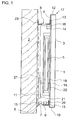
- the figure shows schematically a heatable mirror according to the invention in front of a wall from the side in cross section.
- the mirror 1 has a front side 3, which consists of a glass plate, and a back 4, wherein the back 4 has a mirror coating 22.
- the mirror 1 is fixed by means of holding means 23 to a wall 2.
- the mirror 1 is held at a distance of about 4 cm from the wall 2 by means of a cage 7.
- the cage 7 is fixed by means of the holding means 23 to the wall.
- the cage 7 has holes which are smaller than 4 mm, or slot-shaped openings 9 in such a way that a contact protection is ensured.
- the mirror 1 is heated by means of a resistance heater 5.
- the power supply for the resistance heater 5 is controlled by a control unit 11, which is electrically connected to the resistance heater 5, as a function of the ambient temperature and the temperature of the mirror surface. For this purpose, the temperature of the environment with the aid of a second thermostat 15 at the lower edge 10 of the mirror 1 is measured.
- a thermal switch 16 turns off the power to the resistance heater 5, when the temperature at an upper edge 12 of the mirror z. B. exceeds 85 ° C.
- the mirror 1 is attached to the cage 7 by means of a cantilever 13.
- the edges 10, 17 of the mirror 1, in particular the upper edge 17 and the lower edge 10 extend beyond the cage 7. This additionally protects the electrical components and further reduces the risk of electric shock.
- the cage 7 is preferably connected at some distance from the edges 10, 17 of the mirror 1 with the latter, wherein the connection must be designed so that relative elongations of the order of 4 mm between mirror 1 and cage 7 are made possible. As a result, stresses and damage in the mirror 1 are prevented at different thermal expansions of the components.
- the resistance heater 5 is arranged in the cage 7, the resistance heater 5 is surrounded by two layers 18, 19, namely a first electrically insulating layer 18 and a second electrically insulating layer 19.
- the two layers 18, 19 serve to provide a reliable and stable insulation.
- Control of the power supply as a function of the respective temperatures can also be a temperature control of the temperature of the mirror surface or the front side 3 via a sensor 20 for determining the humidity.
- the mirror 1 is heated.
- a relative humidity of more than 95%, preferably more than 98% is reached.
- the temperature of the surface of the mirror 1 is regulated as a function of the relative humidity.
- the respective sensors 14, 16, 15, 20 are connected via electrical connection lines 21 to the control unit 11.
- the inventive heated mirror 1, in particular for attachment to a wall 2 in a living room, with a mirrored front 3 and a back 4 comprises a planar resistance heater 5 for heating the mirrored front 3, wherein the heating power of the resistance heater 5 based on the mirrored surface at least 0.07 watts / cm 2 .
- the invention is characterized in that a misting of the mirror 1 can be reliably avoided reliably by steam and at the same time a temperature of the living space is made possible, which may be possible to dispense with additional radiator in the living room. This saves space.
Landscapes
- Mirrors, Picture Frames, Photograph Stands, And Related Fastening Devices (AREA)
Applications Claiming Priority (1)
| Application Number | Priority Date | Filing Date | Title |
|---|---|---|---|
| DE200510016536 DE102005016536A1 (de) | 2005-04-08 | 2005-04-08 | Beheizbarer Spiegel für einen Wohnraum |
Publications (1)
| Publication Number | Publication Date |
|---|---|
| EP1711036A1 true EP1711036A1 (fr) | 2006-10-11 |
Family
ID=36608607
Family Applications (1)
| Application Number | Title | Priority Date | Filing Date |
|---|---|---|---|
| EP06007349A Withdrawn EP1711036A1 (fr) | 2005-04-08 | 2006-04-07 | Miroir chauffable pour un espace d'habitation |
Country Status (2)
| Country | Link |
|---|---|
| EP (1) | EP1711036A1 (fr) |
| DE (1) | DE102005016536A1 (fr) |
Families Citing this family (1)
| Publication number | Priority date | Publication date | Assignee | Title |
|---|---|---|---|---|
| DE102008059132A1 (de) * | 2008-11-26 | 2010-05-27 | Joachim Beyl | Luftleitsystem |
Citations (4)
| Publication number | Priority date | Publication date | Assignee | Title |
|---|---|---|---|---|
| US3790748A (en) * | 1971-06-09 | 1974-02-05 | Glaverbel | Mirror having electrical heating means |
| DE2923020A1 (de) * | 1979-06-07 | 1980-12-18 | Hans Weber | Spiegel |
| FR2764050A1 (fr) * | 1997-05-30 | 1998-12-04 | Acome Soc Coop Travailleurs | Dispositif a fonctions de decoration, notamment de miroir, et d'appareil de chauffage electrique |
| FR2770737A1 (fr) * | 1997-10-31 | 1999-05-07 | Muller Et Cie | Miroir chauffant |
Family Cites Families (10)
| Publication number | Priority date | Publication date | Assignee | Title |
|---|---|---|---|---|
| DE831121C (de) * | 1946-09-03 | 1952-02-11 | Saint Gobain | Elektrischer Heizkoerper |
| DE1615130B2 (de) * | 1967-01-27 | 1975-08-07 | Walther 7800 Freiburg Bethge | Verfahren zum Herstellen einer schlierenfreien Heizscheibe |
| FR2109272A5 (en) * | 1970-10-09 | 1972-05-26 | Saint Gobain Pont A Mousson | Heated mirror - with two layers of glass to sandwich reflector and one layer carrying heaters |
| DE2332915C2 (de) * | 1973-06-28 | 1975-01-02 | Glas- Und Spiegelmanufaktur N. Kinon Gmbh, 5100 Aachen | Elektrisch beheizbare Verbundglasscheibe |
| DE3344898C2 (de) * | 1983-12-12 | 1985-11-21 | Hofmann, Gerhard, 8014 Neubiberg | Raumheizgerät |
| DE9010468U1 (de) * | 1990-07-11 | 1990-09-13 | Grund, Otto, 5920 Bad Berleburg | Beheizbarer Spiegel |
| US5380981A (en) * | 1993-05-04 | 1995-01-10 | Feldman; Bernard | Economical bathroom mirror heater |
| US5408069A (en) * | 1993-09-28 | 1995-04-18 | Mischel, Jr.; James V. | Self-defogging mirror |
| DE19711522C2 (de) * | 1997-03-19 | 1999-11-18 | Josef Winter | Elektrisches Flächenheizelement, insbesondere für Spiegel |
| US6664513B1 (en) * | 2002-05-25 | 2003-12-16 | Parkson Industries, Inc. | Wall-mounted mirror heated by convection and radiation |
-
2005
- 2005-04-08 DE DE200510016536 patent/DE102005016536A1/de not_active Withdrawn
-
2006
- 2006-04-07 EP EP06007349A patent/EP1711036A1/fr not_active Withdrawn
Patent Citations (4)
| Publication number | Priority date | Publication date | Assignee | Title |
|---|---|---|---|---|
| US3790748A (en) * | 1971-06-09 | 1974-02-05 | Glaverbel | Mirror having electrical heating means |
| DE2923020A1 (de) * | 1979-06-07 | 1980-12-18 | Hans Weber | Spiegel |
| FR2764050A1 (fr) * | 1997-05-30 | 1998-12-04 | Acome Soc Coop Travailleurs | Dispositif a fonctions de decoration, notamment de miroir, et d'appareil de chauffage electrique |
| FR2770737A1 (fr) * | 1997-10-31 | 1999-05-07 | Muller Et Cie | Miroir chauffant |
Also Published As
| Publication number | Publication date |
|---|---|
| DE102005016536A1 (de) | 2006-10-12 |
Similar Documents
| Publication | Publication Date | Title |
|---|---|---|
| EP0866639B1 (fr) | Chauffage ohmique pour les objects plats, en particulier pour miroirs | |
| DE69816222T2 (de) | Flexibler Flächenheizkörper mit Kontrolleinheit | |
| EP1258171B1 (fr) | Surface de cuisson avec capteur de temperature | |
| WO2015010874A1 (fr) | Véhicule muni d'un dispositif de chauffage électrique | |
| DE3205658A1 (de) | Elektroherd mit temperaturwarneinrichtung | |
| DE2500586C2 (fr) | ||
| DE3011063A1 (de) | Behaelter zum erwaermen von fluessigkeiten | |
| DE10021512A1 (de) | Elektrische Heizeinheit, insbesondere für flüssige Medien | |
| DE60305464T2 (de) | Elektrische heizbaugruppe | |
| DE8305868U1 (de) | Elektrischer strahlungsheizer fuer herde mit glaskeramikdeckplatten | |
| EP0731624B1 (fr) | Dispositif de chauffage pour lits à eau | |
| DE3613902A1 (de) | Kochplatte, insbesondere fuer grosskuechen-herde | |
| EP1711036A1 (fr) | Miroir chauffable pour un espace d'habitation | |
| EP1448024A2 (fr) | Equipement du chauffage avec deux domaines | |
| DE60131255T2 (de) | Temperatursensor | |
| EP0199809A1 (fr) | Radiateurs a accumulation | |
| DE602005001501T2 (de) | Elektrische heizanordnung | |
| EP0927428A1 (fr) | Element chauffant a rayonnement pour une zone de cuisson | |
| DE10065215A1 (de) | Gargerät | |
| WO2001062046A1 (fr) | Ensemble plaque de cuisson dote d'un capteur de temperature | |
| DE2919968C3 (de) | Elektrisch beheizbares Spiegelglas für Kraftfahrzeugaußenspiegel | |
| DE10019238A1 (de) | Wasserkocher mit einstellbarer Wassertemperatur | |
| WO2001062047A1 (fr) | Espace de cuisson a sonde pyrometrique | |
| DE2205358A1 (de) | Überhitzungsschutz an elektrischen Sauna-Aggregaten | |
| DE4221626A1 (de) | Infrarot-Strahlungsheizeinrichtung |
Legal Events
| Date | Code | Title | Description |
|---|---|---|---|
| PUAI | Public reference made under article 153(3) epc to a published international application that has entered the european phase |
Free format text: ORIGINAL CODE: 0009012 |
|
| AK | Designated contracting states |
Kind code of ref document: A1 Designated state(s): AT BE BG CH CY CZ DE DK EE ES FI FR GB GR HU IE IS IT LI LT LU LV MC NL PL PT RO SE SI SK TR |
|
| AX | Request for extension of the european patent |
Extension state: AL BA HR MK YU |
|
| AKX | Designation fees paid | ||
| RAP1 | Party data changed (applicant data changed or rights of an application transferred) |
Owner name: MARX, KLAUS Owner name: LAMBERT, DIETER |
|
| REG | Reference to a national code |
Ref country code: DE Ref legal event code: 8566 |
|
| STAA | Information on the status of an ep patent application or granted ep patent |
Free format text: STATUS: THE APPLICATION IS DEEMED TO BE WITHDRAWN |
|
| 18D | Application deemed to be withdrawn |
Effective date: 20070412 |