EP1712199A2 - Système d'implantation pour soin implantologique du mâchoire immédiatement chargeable - Google Patents
Système d'implantation pour soin implantologique du mâchoire immédiatement chargeable Download PDFInfo
- Publication number
- EP1712199A2 EP1712199A2 EP06007629A EP06007629A EP1712199A2 EP 1712199 A2 EP1712199 A2 EP 1712199A2 EP 06007629 A EP06007629 A EP 06007629A EP 06007629 A EP06007629 A EP 06007629A EP 1712199 A2 EP1712199 A2 EP 1712199A2
- Authority
- EP
- European Patent Office
- Prior art keywords
- implant
- drill
- head
- bore
- abutment
- Prior art date
- Legal status (The legal status is an assumption and is not a legal conclusion. Google has not performed a legal analysis and makes no representation as to the accuracy of the status listed.)
- Withdrawn
Links
Images


Classifications
-
- A—HUMAN NECESSITIES
- A61—MEDICAL OR VETERINARY SCIENCE; HYGIENE
- A61C—DENTISTRY; APPARATUS OR METHODS FOR ORAL OR DENTAL HYGIENE
- A61C8/00—Means to be fixed to the jaw-bone for consolidating natural teeth or for fixing dental prostheses thereon; Dental implants; Implanting tools
- A61C8/001—Multiple implanting technique, i.e. multiple component implants introduced in the jaw from different directions
-
- A—HUMAN NECESSITIES
- A61—MEDICAL OR VETERINARY SCIENCE; HYGIENE
- A61C—DENTISTRY; APPARATUS OR METHODS FOR ORAL OR DENTAL HYGIENE
- A61C1/00—Dental machines for boring or cutting ; General features of dental machines or apparatus, e.g. hand-piece design
- A61C1/08—Machine parts specially adapted for dentistry
- A61C1/082—Positioning or guiding, e.g. of drills
- A61C1/084—Positioning or guiding, e.g. of drills of implanting tools
-
- A—HUMAN NECESSITIES
- A61—MEDICAL OR VETERINARY SCIENCE; HYGIENE
- A61C—DENTISTRY; APPARATUS OR METHODS FOR ORAL OR DENTAL HYGIENE
- A61C8/00—Means to be fixed to the jaw-bone for consolidating natural teeth or for fixing dental prostheses thereon; Dental implants; Implanting tools
- A61C8/0018—Means to be fixed to the jaw-bone for consolidating natural teeth or for fixing dental prostheses thereon; Dental implants; Implanting tools characterised by the shape
- A61C8/003—Transmandibular implants
-
- A—HUMAN NECESSITIES
- A61—MEDICAL OR VETERINARY SCIENCE; HYGIENE
- A61C—DENTISTRY; APPARATUS OR METHODS FOR ORAL OR DENTAL HYGIENE
- A61C8/00—Means to be fixed to the jaw-bone for consolidating natural teeth or for fixing dental prostheses thereon; Dental implants; Implanting tools
- A61C8/0048—Connecting the upper structure to the implant, e.g. bridging bars
-
- A—HUMAN NECESSITIES
- A61—MEDICAL OR VETERINARY SCIENCE; HYGIENE
- A61C—DENTISTRY; APPARATUS OR METHODS FOR ORAL OR DENTAL HYGIENE
- A61C8/00—Means to be fixed to the jaw-bone for consolidating natural teeth or for fixing dental prostheses thereon; Dental implants; Implanting tools
- A61C8/0089—Implanting tools or instruments
Definitions
- the invention relates to an implantation system for an immediately loadable implantation of the jaw and the components of this system comprising at least one dental implant, a drill key and a Fixturelement.
- the implant-prosthetic restoration in particular completely toothless and partially already atrophied jaws, has long been a problem. Complete or partial loss of teeth results in generalized or local atrophy, which is exacerbated by the use of removable dentures.
- the toothless, mechanically less stable maxillary ponsum atrophies at the centripetal level loses height and width under the unphysiological chewing forces of the prosthesis, and occasionally makes it impossible to produce a sufficient maxillary prosthesis after a long period of edentulousness.
- the necessity of placing artificial teeth on the atrophied alveolar ridge for static reasons in total dentures leads to an inadequate esthetics with at best sufficient chewing function.
- conservative treatment technology still prefers subgingival healing of the implants, which involves a two-step process with a relatively long treatment duration.
- second step another surgical procedure for implantation must be carried out. After the impression of the implant position, a prosthetic superstructure is made and fixed in the mouth on the implants.
- IPI immediate provisional implants
- immediate loading of the permanent implant with open healing would be desirable.
- the immediate implant load is currently even when supplying the mechanically stronger Lower jaw recommended only under certain conditions, for example, include relatively good bone quantity and quality. However, this is often not the case in older patients or in long-term edentulous and thus atrophied pines.
- the immediate loading of the maxilla is far more critical, since there is generally a lower bone volume and cancellous bone material. For this reason, the immediate loading of permanent implants for the lower jaw with favorable disposition is no longer unusual, while it would be critical for the upper jaw to judge, since there are no positive reports.
- Such computer-aided planning is used, for example, in an implantation concept known under the slogan "Teeth in an Hour” ( Yildirim, M. et al., "Immediate Treatment of the Edentulous Jaw: Teeth in an Hour", Implantology 2004, 12, 341-358 ).
- a virtual planning environment is combined with a transgingival insertion technique.
- an existing denture base is adapted exactly to the mucosal argument.
- imaging techniques the bone situation and mucosal thickness are accurately determined. The number, position, length and thickness of the implants and the abutments can thus be precisely planned in advance.
- the result of the planning is transferred to a model for the prosthesis using a stereolithography method.
- a drilling template in the form of the denture base is made.
- the transfer template is then supported on the mucosa-supported patient and fixed in the alveolar bone with vestibular fixation screws.
- Guide aids are used to pierce gingiva and bone.
- the implant insertion is transgingival with an insertion aid.
- After removal of the surgical template becomes the blocked (bridged) prosthetic superstructure put on and attached. The result is a semi-permanent restoration, after healing, the prosthetic part can be replaced.
- the invention is therefore based on the object to provide new options for the immediate prosthetic restoration of partial or edentulous patients and in particular for the dental prosthesis in the upper jaw available.
- the invention is based on the finding that an additional, internal, individual fixation of the implants in the jaw can reduce the risk of micromotion far enough to allow an immediate loading of maxillary implants.
- a locking of the implants can be made additionally.
- the system can also be used to protect closed healing dental implants from stress during the sensitive osseointegration phase in a conventional manner.
- the system can also be used to generally secure screw implants against twisting and to further mechanically stabilize them.
- the implantation system according to the invention and its constituents are particularly advantageous in the case of age-related or disease-related jaw atrophy and in tumor patients with defect dissections for direct prosthetic rehabilitation.
- the implantation system according to the invention further makes it possible to provide the implantation by means of a rigid framework with a suitable connection (cone or thread) and thereby to block several individual implants.
- the direct primary blocking can be done as usual and known in the art by a rigid framework.
- the rigid framework may be located within the prosthetic superstructure (bridging by means of the prosthesis via the implant heads), or a composite plate may be provided in the region of the alveolar process.
- individual implants, larger areas or all implants of a jaw may be blocked.
- For a total blockage is a horseshoe-shaped construction, ie to provide a horseshoe-shaped transgingival composite panel.
- Such a composite plate for the implantation system has at least two holes designed for the implementation of dental implants.
- the dental implant according to the invention for use in the implantation system shown here has an implant body which is substantially cylindrical or conically tapering at the usual implants and an implant head fixedly or detachably connected thereto which can be used as an abutment for a prosthetic superstructure.
- the dental implant according to the invention is characterized by a in the implant body below the head end, preferably in the lower third, substantially transversely or obliquely to the implant main axis extending through bore (hereinafter also called "Fixturbohrung") and by at least one Marking element in an accessible after insertion area of the implant in spatially exact assignment to the entrance of the fixture bore.
- any desired dental implant can be modified such that it can be secured in the manner according to the invention with the fixture element.
- the dental implant body is a solid screw implant having an outer diameter of between about 3.5 and 5 mm.
- the marking element may preferably be a groove or a pin or web. There may be several marking elements.
- the marking element can be located on a recess or inner bore in the implant body, on the alternatively usable as an abutment implant head, an adapter for the attachment of an abutment or the form-fitting matching drill wrench is placed, in turn, has a gegen Dermates marking element, ie, for example, a pin or web for engaging in the groove or a groove into which a pin or web can engage the implant.
- a gegen Dermats marking element ie, for example, a pin or web for engaging in the groove or a groove into which a pin or web can engage the implant.
- the marking element e.g. in the form of a color marking, either on the outside of the implant neck or on the implant head which can be used as an abutment and the form-fitting matching drill key can be attached to the abutment.
- the marking which is located in exact spatial relation to the fixture bore, is necessary in order to be able to align the implant with the fixture bore to the patient's oral forecourt. Since the inventive Fixturelement is introduced only when the implant has already been inserted into the jaw of the patient, the Fixturbohrung in the implant at this time is no longer visible to the surgeon.
- a drilling key was developed as a "drill guide", which allows a drill to be aligned precisely from the outside to the fixture bore, to pass it through the bore and in extension Drill the fixture hole in the jawbone and then insert the fixture element here.
- the Bohr arrangements Vietnamese the Bohr nowadaysls can preferably be designed so that the Fixturelement can be introduced directly through the Bohr associateds bamboo in the Fixturbohrung of the implant.
- the Fixturelement be designed as a headless element, such as a headless Allen screw to be fastened with a special tool.
- a detachable sleeve whose inner width is designed for the leadership of a drill largely without play and which can be inserted into a bore on the drill key, the leadership of the Fixtutelements exactly in the direction of Fixturbohrung serves.
- the Bohrkeyarm can also be designed in several parts, in which case the lower part of the arm with the Bohr Operations bamboo is removable. This part is removed after drilling, so that the Fixturelement then directly or with the help of an existing in another forearm guide assistance, i.a. larger width, can be used.
- the drill key according to the invention for use in the implantation system described here is characterized by an arcuate arm between a drill key head which can be positively fastened in or on an implant head or implant body and a drill guide integrated at the opposite end of the arm, which guides the guide Drill (Vorbohrers) largely without clearance along a given by the drilling aid drilling axis allows.
- the drilling axis predetermined by the Bohr entries Vietnamese drilling axis is transversely or obliquely to the implant main axis, on which the Bohr nowadayslkopf is aligned, preferably at an angle between 20 ° and 160 °, more preferably between 30 ° and 150 °.
- the main axis of the implant and the drilling axis do not have to cross each other, the angles then refer to the projection of the axes in one plane.
- the axes will generally cross or approximately intersect. The mechanical stability should be better for not exactly crossing axes.
- the drill key head is designed in such a way that it can be placed in a gripping manner on an implant by means of a positive plug connection in or around the implant body, the implant head or an abutment placed with or without an adapter, with respect to the angle of rotation about the implant main axis in a spatially unique position.
- at least one marking element is provided, which is suitable for engaging in a matching marking counterpart on the implant, for example a projection or web or also a groove, as already described above.
- the solution according to the invention comprises a fixture element for the additional and individual (internal) fixture of the implant in the patient's bone transversely or obliquely to the implant major axis, so that the implant is secured against twisting, twisting, tilting and the like and additionally mechanically stabilized , Micromovements are thereby prevented or at least significantly reduced.
- the Fixturelement may be pin, screw or nail-shaped and is precisely fit through the substantially transversely or obliquely extending bore of a dental implant, which is referred to here as Fixturbohrung used.
- the length of the element is preferably 0.5 to 3 cm, in particular 1 to 2 cm, the diameter 1 to 3 mm. It may be a pin or nail, which may for example be provided with a frikomsfördemden surface structure (A corresponding surface can be provided within the Fixturbohrung). Currently, a screw nail design having threads only at its distal end, which are preferably cutting threads, is considered to be particularly preferred.
- the Fixturelement be a screw that is either feasible without play through the Fixturbohrung of the implant or whose thread is formed to match an internal thread of the Fixturbohrung of the implant.
- the Fixturelement can consist of the usual materials for the associated dental implants.
- the implant primarily titanium, titanium-plastic hybrids or plastic cores with titanium splinter surface.
- a Fixturelement which consists of a resorbable plastic and digested after about 3-4 months by metabolic processes. Such resorbable plastics are known in the art.
- FIG. 1 shows, in a highly simplified, schematic representation, a maxillary implant restoration indicated as a whole by 100 with a horseshoe-shaped curved (or milled) composite plate 10 and eight individual implants 20 blocked therein, which are intended for immediate loading.
- each of the eight individual implants 20 is additionally secured with a Fixturelement 30 against turning and tilting movements.
- the composite plate 10 can initially be prefixed with 2 to 3 mini screws (indicated by arrows). It is then checked whether the plate fits well, and - in this example eight - pre-drilled holes for definitive implants 20 are set. Finally, the insertion of the implants 20 and the fixture takes place through the fixture elements 30.
- Figure 2 also shows schematically a single dental implant 20 with internal fixture by a Fixturelement 30, here a screw nail with head and a screw-down (40a) Abutment (40).
- the superstructure (50) (crown, bridge or prosthesis) may be cemented or screwed.
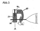
- FIG. 3 shows the basic procedure for the fixture with a later to be used Fixturelement in a schematic sketch.
- a drill key 60 attached and connected by means of a screw (40 a) with the implant 20.
- the drilling key 60 is aligned exactly with the fixture bore 80 in the implant 20 so that the pilot drill A can be passed through the drilling guide aid 88 and the fixture bore 80.
- the drill key 60 extends arcuately around the mucosa, such that the drill guide aid 88 in the drill key automatically steers the pilot drill into the prefabricated channel of the bore 80.
- the drill key 60 is removed and the fixture element, not shown here, used and, if present, firmly tightened with the cutting threads. Thereafter, the implant 20 is fixed as shown in Figures 1 and 2.
- the angle between the main axis of the implant 20 and the Fixturelement 30 need not be 90 °, as indicated here, but the element can be used in any way transversely or obliquely to the implant, as it was determined due to the planning as optimal.
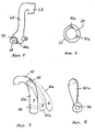
- Fig. 4 shows an embodiment of a screw implant with internal fixture.
- the implant 20 consists of an implant body 22 tapering conically to the distal end (FIG. 4b) and a screw-on implant head 24 (FIG. 4a) with a conically shaped upper end for attachment of a single dental crown or a bridged prosthetic superstructure.
- the fixture element 30 shown in Fig. 4c here is a screw nail with tulip-shaped slot head.
- the length of the screw nail is in the example 1 cm, the diameter 2 mm and must be shortened if necessary after pre-drilling intra-op.
- the upper end of the implant body 22 is here designed hexagonal, but may preferably also be round, so that the implant can rotate positively through the composite plate into the bone.
- the screw-nut-shaped ring 26 at the upper end of the implant body 22 serves for better handling when screwing.
- FIG. 4d shows a plan view of the ring 26.
- the implant body 22 has an internal thread 28 for screwing on the head 24.
- the recess of this internal thread 26 can now be used, as shown in FIG. 4e, to the drilling key 60th set up with his drill head 68 on the implant body.
- the exact positioning is ensured by the groove 70a present in the implant ring 26, into which engages a projection 70b formed on the drill key.
- the groove 70a marks the location of the entrance of the fixture bore 80 as a marker.
- the arcuate arm 66 of the drill wrench 60 then brings the drill guide aid 88 into exact alignment with the fixture bore 80 so that both lie on a common axis along which the pilot drill A can be guided, as shown in Fig. 3.
- the drill key 60 is fixed here with a screw 90.
- the head 24 is screwed onto the (inserted) implant (implant body 22) and the fixture screw 30 is passed through the fixture bore 80 and screwed tight in the bone.
- Fig. 5 shows another embodiment of a drilling wrench 60 (like reference numerals designate corresponding components) in which the drill guide aid 88 is located within a removable sleeve 89.
- the sleeve 89 has an inner width of such dimensions that it is designed as Bohr Operations bamboo 88 for the drill, not shown here - essentially without play the drill during drilling -.
- the sleeve itself is inserted into a bore 88 a on the drill key 60, which serves to guide the fixture element 30 exactly in the direction of the fixture bore 80 of the implant 20.
- the sleeve is removed after drilling by hand or with a specially adapted tool.
- the sleeve 89 may be fixed with a grub screw 90.
- This grub screw 90 may itself be formed as a sleeve and serve for the supply of rinse water for flushing the borehole, if this is arranged on the sleeve 89 a matching, additional transverse threaded hole.
- Fig. 6 shows an alternative embodiment to Fig. 4d, wherein the internal thread 28 here two markers 70a are arranged, which allow the unique positioning of the drilling wrench and possibly other tools.
- Fig. 7 shows an embodiment of a multi-part Bohr memorilarm.
- the drill bit 60 has a removable drill lower arm 60a, with three sizes I, II and II to be used optionally. Forearm can be changed or removed at position 64 (attachment, latch, push button). After drilling through the drilling aid 88, the lower arm - here 60a - is removed and the Fixturelement 30 is used either directly or by a newly scheduled forearm with other, matched to the Fixturelement hole.
- Both the fixture bore 80 and the drill guide aid 88 or the fixture guide aid 88a may be provided with a conical extension at the entrance to facilitate insertion of the fixture element or the drill.
- stop stop element
- the stopper is arranged in each case so that the bore can be made exactly to the correct drilling depth
Landscapes
- Health & Medical Sciences (AREA)
- Oral & Maxillofacial Surgery (AREA)
- Dentistry (AREA)
- Epidemiology (AREA)
- Life Sciences & Earth Sciences (AREA)
- Animal Behavior & Ethology (AREA)
- General Health & Medical Sciences (AREA)
- Public Health (AREA)
- Veterinary Medicine (AREA)
- Orthopedic Medicine & Surgery (AREA)
- Dental Prosthetics (AREA)
Applications Claiming Priority (1)
| Application Number | Priority Date | Filing Date | Title |
|---|---|---|---|
| DE200510016740 DE102005016740A1 (de) | 2005-04-11 | 2005-04-11 | Implantations-System für eine sofort belastbare implantologische Versorgung des Kiefers |
Publications (2)
| Publication Number | Publication Date |
|---|---|
| EP1712199A2 true EP1712199A2 (fr) | 2006-10-18 |
| EP1712199A3 EP1712199A3 (fr) | 2006-11-02 |
Family
ID=36607317
Family Applications (1)
| Application Number | Title | Priority Date | Filing Date |
|---|---|---|---|
| EP06007629A Withdrawn EP1712199A3 (fr) | 2005-04-11 | 2006-04-11 | Système d'implantation pour soin implantologique du mâchoire immédiatement chargeable |
Country Status (2)
| Country | Link |
|---|---|
| EP (1) | EP1712199A3 (fr) |
| DE (1) | DE102005016740A1 (fr) |
Cited By (2)
| Publication number | Priority date | Publication date | Assignee | Title |
|---|---|---|---|---|
| DE202013011239U1 (de) * | 2013-12-17 | 2014-04-04 | Biomed Est. | Dentalimplantat und auf dem Implantat basierende provisorische Konstruktion |
| EP2759279A1 (fr) * | 2013-01-24 | 2014-07-30 | Heraeus Kulzer GmbH | Dispositif d'ancrage entre les cylindres et les éléments d'écartement des touches de position pour implants dentaires |
Families Citing this family (1)
| Publication number | Priority date | Publication date | Assignee | Title |
|---|---|---|---|---|
| KR102391077B1 (ko) * | 2021-08-04 | 2022-04-26 | 장원석 | 지지나사 가이드를 갖는 측벽지지 임플란트 시스템 |
Family Cites Families (8)
| Publication number | Priority date | Publication date | Assignee | Title |
|---|---|---|---|---|
| US3579831A (en) * | 1969-03-05 | 1971-05-25 | Irving J Stevens | Bone implant |
| US3981079A (en) * | 1973-08-23 | 1976-09-21 | Lenczycki Joseph J | Dental implant and method of mounting the same in the jaw bone |
| IT1012963B (it) * | 1974-05-30 | 1977-03-10 | Pasqualini Ugo | Impianto particolarmente per implantologia endcossea |
| FR2720264B1 (fr) * | 1994-05-31 | 1996-09-27 | Bruno Bompard | Matériel d'implant dentaire et dispositif pour sa mise en place. |
| US5542847A (en) * | 1994-09-09 | 1996-08-06 | Joseph Y. Margulies | Method, apparatus and device for dental prosthesis implantation |
| FR2797171B1 (fr) * | 1999-08-06 | 2002-02-08 | Bruno Jacques Hubert Bompard | Dispositif pour la mise en place d'implant dentaire |
| AT407606B (de) * | 2000-01-27 | 2001-05-25 | Haas Robert Dr | Positioniervorrichtung |
| IL138457A0 (en) * | 2000-09-09 | 2001-10-31 | Advanced Dental Engineering Lt | Bi-cortical dental implant |
-
2005
- 2005-04-11 DE DE200510016740 patent/DE102005016740A1/de not_active Ceased
-
2006
- 2006-04-11 EP EP06007629A patent/EP1712199A3/fr not_active Withdrawn
Cited By (3)
| Publication number | Priority date | Publication date | Assignee | Title |
|---|---|---|---|---|
| EP2759279A1 (fr) * | 2013-01-24 | 2014-07-30 | Heraeus Kulzer GmbH | Dispositif d'ancrage entre les cylindres et les éléments d'écartement des touches de position pour implants dentaires |
| WO2014114316A1 (fr) * | 2013-01-24 | 2014-07-31 | Heraeus Kulzer Gmbh | Dispositif d'ancrage entre des cylindres et des écarteurs de clavettes de positionnement d'implants dentaires |
| DE202013011239U1 (de) * | 2013-12-17 | 2014-04-04 | Biomed Est. | Dentalimplantat und auf dem Implantat basierende provisorische Konstruktion |
Also Published As
| Publication number | Publication date |
|---|---|
| DE102005016740A1 (de) | 2006-10-12 |
| EP1712199A3 (fr) | 2006-11-02 |
Similar Documents
| Publication | Publication Date | Title |
|---|---|---|
| EP1663051B1 (fr) | Vis de positionnement pour produire une prothese dentaire pour une machoire partiellement ou completement depourvue de dents | |
| DE102012011238B4 (de) | Verfahren zur Herstellung eines Laboranalogs für Dentalimplantate | |
| EP1855610A1 (fr) | Systeme d'implant dentaire comportant une ou deux parties | |
| DE3315329A1 (de) | In den knochen einsetzbares zahnimplantat-system | |
| EP2010092A1 (fr) | Implant dentaire et procédé de fabrication de celui-ci | |
| EP2364124A1 (fr) | Implant dentaire destiné à être inséré dans une mâchoire pour fixer une dent artificielle | |
| DE102005006979A1 (de) | Keramisches enossales Zahnimplantat | |
| EP3297569A1 (fr) | Jeu d'insertion pour implant dentaire individuel intra-osseux | |
| EP1742592B1 (fr) | Porte-empreinte | |
| DE19635619A1 (de) | Implantatsysteme sowie Verfahren und Werkzeuge zum Implantieren im zahnlosen Kiefer | |
| DE102020209688A1 (de) | Implantationssystem und Aufbauelement für ein Implantationssystem | |
| EP1712199A2 (fr) | Système d'implantation pour soin implantologique du mâchoire immédiatement chargeable | |
| DE202009009789U1 (de) | Interimsimplantat zum Einsatz als temporärer Zahnwurzelersatz und Setzinstrument für ein Implantat | |
| DE10033918B4 (de) | Vorrichtung / Implantat zur geführten Distraktionsosteogenese in atrophierten alveolären Kieferknochen | |
| DE4036753A1 (de) | Vorrichtung zur durchfuehrung eines verfahrens zur zahnaerztlichen implantation | |
| WO2020020945A1 (fr) | Gabarit de forage pour une intervention chirurgicale maxillaire | |
| CH707689A1 (de) | Zahnimplatat. | |
| DE102004053434B4 (de) | Implantatsystem | |
| EP2606848A1 (fr) | Dispositif de positionnement de forage pour un implant | |
| DE20219917U1 (de) | Subgingivale Verbindungsvorrichtung für Satellitenimplantate | |
| DE3736978A1 (de) | Dentalimplantat zur befestigung von zahnersatz | |
| DE4335864C2 (de) | Verfahren zur Herstellung einer Suprastruktur und Verbindung mit einem Implantat | |
| EP1582174A2 (fr) | Poinçonneuse | |
| DE202021105284U1 (de) | Abdeckelement zur wenigstens zeitweisen Überdeckung eines Wundbereichs | |
| DE102020103395A1 (de) | Implantat-Knochenersatz-Block |
Legal Events
| Date | Code | Title | Description |
|---|---|---|---|
| PUAI | Public reference made under article 153(3) epc to a published international application that has entered the european phase |
Free format text: ORIGINAL CODE: 0009012 |
|
| PUAL | Search report despatched |
Free format text: ORIGINAL CODE: 0009013 |
|
| AK | Designated contracting states |
Kind code of ref document: A2 Designated state(s): AT BE BG CH CY CZ DE DK EE ES FI FR GB GR HU IE IS IT LI LT LU LV MC NL PL PT RO SE SI SK TR |
|
| AX | Request for extension of the european patent |
Extension state: AL BA HR MK YU |
|
| AK | Designated contracting states |
Kind code of ref document: A3 Designated state(s): AT BE BG CH CY CZ DE DK EE ES FI FR GB GR HU IE IS IT LI LT LU LV MC NL PL PT RO SE SI SK TR |
|
| AX | Request for extension of the european patent |
Extension state: AL BA HR MK YU |
|
| AKX | Designation fees paid | ||
| STAA | Information on the status of an ep patent application or granted ep patent |
Free format text: STATUS: THE APPLICATION IS DEEMED TO BE WITHDRAWN |
|
| 18D | Application deemed to be withdrawn |
Effective date: 20070503 |
|
| REG | Reference to a national code |
Ref country code: DE Ref legal event code: 8566 |