EP1712251A1 - Fil de guidage - Google Patents
Fil de guidage Download PDFInfo
- Publication number
- EP1712251A1 EP1712251A1 EP06112479A EP06112479A EP1712251A1 EP 1712251 A1 EP1712251 A1 EP 1712251A1 EP 06112479 A EP06112479 A EP 06112479A EP 06112479 A EP06112479 A EP 06112479A EP 1712251 A1 EP1712251 A1 EP 1712251A1
- Authority
- EP
- European Patent Office
- Prior art keywords
- wire
- coating layer
- guide wire
- outside diameter
- distal end
- Prior art date
- Legal status (The legal status is an assumption and is not a legal conclusion. Google has not performed a legal analysis and makes no representation as to the accuracy of the status listed.)
- Granted
Links
- 239000011247 coating layer Substances 0.000 claims abstract description 210
- 238000003466 welding Methods 0.000 claims abstract description 53
- 230000002093 peripheral effect Effects 0.000 claims abstract description 37
- 229910045601 alloy Inorganic materials 0.000 claims description 63
- 239000000956 alloy Substances 0.000 claims description 63
- 239000007769 metal material Substances 0.000 claims description 26
- 230000003247 decreasing effect Effects 0.000 claims description 22
- KHYBPSFKEHXSLX-UHFFFAOYSA-N iminotitanium Chemical compound [Ti]=N KHYBPSFKEHXSLX-UHFFFAOYSA-N 0.000 claims description 22
- 229910001000 nickel titanium Inorganic materials 0.000 claims description 22
- 229910052751 metal Inorganic materials 0.000 claims description 20
- 239000002184 metal Substances 0.000 claims description 20
- 238000012545 processing Methods 0.000 claims description 16
- 239000000463 material Substances 0.000 description 133
- 229920005989 resin Polymers 0.000 description 122
- 239000011347 resin Substances 0.000 description 122
- 210000004204 blood vessel Anatomy 0.000 description 24
- 230000004044 response Effects 0.000 description 24
- 238000000034 method Methods 0.000 description 22
- -1 polyethylene Polymers 0.000 description 18
- 239000000126 substance Substances 0.000 description 16
- 238000005452 bending Methods 0.000 description 14
- 239000000470 constituent Substances 0.000 description 14
- 238000011282 treatment Methods 0.000 description 14
- PXHVJJICTQNCMI-UHFFFAOYSA-N nickel Substances [Ni] PXHVJJICTQNCMI-UHFFFAOYSA-N 0.000 description 13
- 239000002131 composite material Substances 0.000 description 12
- 239000011248 coating agent Substances 0.000 description 11
- 238000000576 coating method Methods 0.000 description 11
- 239000010410 layer Substances 0.000 description 11
- 229920002050 silicone resin Polymers 0.000 description 10
- 210000000013 bile duct Anatomy 0.000 description 9
- 210000004351 coronary vessel Anatomy 0.000 description 8
- 230000002708 enhancing effect Effects 0.000 description 8
- 210000000277 pancreatic duct Anatomy 0.000 description 8
- 230000000704 physical effect Effects 0.000 description 8
- 229910001220 stainless steel Inorganic materials 0.000 description 8
- 229910000531 Co alloy Inorganic materials 0.000 description 7
- 229910018487 Ni—Cr Inorganic materials 0.000 description 7
- 229920001971 elastomer Polymers 0.000 description 7
- 229910052759 nickel Inorganic materials 0.000 description 7
- 229920002725 thermoplastic elastomer Polymers 0.000 description 7
- 239000004952 Polyamide Substances 0.000 description 6
- 239000013013 elastic material Substances 0.000 description 6
- 239000000203 mixture Substances 0.000 description 6
- 229910000510 noble metal Inorganic materials 0.000 description 6
- 229920002647 polyamide Polymers 0.000 description 6
- 229920000728 polyester Polymers 0.000 description 6
- 239000007779 soft material Substances 0.000 description 6
- 238000010438 heat treatment Methods 0.000 description 5
- 229920002635 polyurethane Polymers 0.000 description 5
- 239000004814 polyurethane Substances 0.000 description 5
- 238000004904 shortening Methods 0.000 description 5
- 239000004698 Polyethylene Substances 0.000 description 4
- 239000004642 Polyimide Substances 0.000 description 4
- 239000004743 Polypropylene Substances 0.000 description 4
- 239000004793 Polystyrene Substances 0.000 description 4
- 238000005219 brazing Methods 0.000 description 4
- 229920001577 copolymer Polymers 0.000 description 4
- 230000000694 effects Effects 0.000 description 4
- 239000000806 elastomer Substances 0.000 description 4
- 238000005530 etching Methods 0.000 description 4
- 229920000840 ethylene tetrafluoroethylene copolymer Polymers 0.000 description 4
- 238000004299 exfoliation Methods 0.000 description 4
- 238000000227 grinding Methods 0.000 description 4
- 238000003754 machining Methods 0.000 description 4
- BASFCYQUMIYNBI-UHFFFAOYSA-N platinum Chemical compound [Pt] BASFCYQUMIYNBI-UHFFFAOYSA-N 0.000 description 4
- 238000005498 polishing Methods 0.000 description 4
- 229920000573 polyethylene Polymers 0.000 description 4
- 229920001721 polyimide Polymers 0.000 description 4
- 229920000098 polyolefin Polymers 0.000 description 4
- 229920001155 polypropylene Polymers 0.000 description 4
- 229920002223 polystyrene Polymers 0.000 description 4
- 239000004810 polytetrafluoroethylene Substances 0.000 description 4
- 229920001343 polytetrafluoroethylene Polymers 0.000 description 4
- 239000004800 polyvinyl chloride Substances 0.000 description 4
- 229920000915 polyvinyl chloride Polymers 0.000 description 4
- 239000005060 rubber Substances 0.000 description 4
- 229910000679 solder Inorganic materials 0.000 description 4
- 239000010935 stainless steel Substances 0.000 description 4
- 210000002376 aorta thoracic Anatomy 0.000 description 3
- 230000008859 change Effects 0.000 description 3
- 239000002872 contrast media Substances 0.000 description 3
- 238000001816 cooling Methods 0.000 description 3
- 238000010586 diagram Methods 0.000 description 3
- 230000000916 dilatatory effect Effects 0.000 description 3
- 238000005304 joining Methods 0.000 description 3
- 230000003902 lesion Effects 0.000 description 3
- 239000000155 melt Substances 0.000 description 3
- 150000002739 metals Chemical class 0.000 description 3
- 238000000926 separation method Methods 0.000 description 3
- 238000007711 solidification Methods 0.000 description 3
- 230000008023 solidification Effects 0.000 description 3
- HRPVXLWXLXDGHG-UHFFFAOYSA-N Acrylamide Chemical compound NC(=O)C=C HRPVXLWXLXDGHG-UHFFFAOYSA-N 0.000 description 2
- 239000004677 Nylon Substances 0.000 description 2
- 229920003171 Poly (ethylene oxide) Polymers 0.000 description 2
- 239000004372 Polyvinyl alcohol Substances 0.000 description 2
- 238000010521 absorption reaction Methods 0.000 description 2
- 239000000853 adhesive Substances 0.000 description 2
- 230000001070 adhesive effect Effects 0.000 description 2
- 229910052790 beryllium Inorganic materials 0.000 description 2
- 229920001400 block copolymer Polymers 0.000 description 2
- 239000001913 cellulose Substances 0.000 description 2
- 229920002678 cellulose Polymers 0.000 description 2
- HVYWMOMLDIMFJA-DPAQBDIFSA-N cholesterol Chemical compound C1C=C2C[C@@H](O)CC[C@]2(C)[C@@H]2[C@@H]1[C@@H]1CC[C@H]([C@H](C)CCCC(C)C)[C@@]1(C)CC2 HVYWMOMLDIMFJA-DPAQBDIFSA-N 0.000 description 2
- RKTYLMNFRDHKIL-UHFFFAOYSA-N copper;5,10,15,20-tetraphenylporphyrin-22,24-diide Chemical compound [Cu+2].C1=CC(C(=C2C=CC([N-]2)=C(C=2C=CC=CC=2)C=2C=CC(N=2)=C(C=2C=CC=CC=2)C2=CC=C3[N-]2)C=2C=CC=CC=2)=NC1=C3C1=CC=CC=C1 RKTYLMNFRDHKIL-UHFFFAOYSA-N 0.000 description 2
- 210000001198 duodenum Anatomy 0.000 description 2
- 238000007459 endoscopic retrograde cholangiopancreatography Methods 0.000 description 2
- 238000007463 endoscopic sphincterotomy Methods 0.000 description 2
- 230000002349 favourable effect Effects 0.000 description 2
- 239000000945 filler Substances 0.000 description 2
- PCHJSUWPFVWCPO-UHFFFAOYSA-N gold Chemical compound [Au] PCHJSUWPFVWCPO-UHFFFAOYSA-N 0.000 description 2
- 229910052737 gold Inorganic materials 0.000 description 2
- 239000010931 gold Substances 0.000 description 2
- 230000006872 improvement Effects 0.000 description 2
- 238000003780 insertion Methods 0.000 description 2
- 230000037431 insertion Effects 0.000 description 2
- 229920000126 latex Polymers 0.000 description 2
- 230000033001 locomotion Effects 0.000 description 2
- FPYJFEHAWHCUMM-UHFFFAOYSA-N maleic anhydride Chemical compound O=C1OC(=O)C=C1 FPYJFEHAWHCUMM-UHFFFAOYSA-N 0.000 description 2
- 238000004519 manufacturing process Methods 0.000 description 2
- 229910052750 molybdenum Inorganic materials 0.000 description 2
- DEOMKWCLRQFEQZ-UHFFFAOYSA-N n,n-dimethylprop-2-enamide;2-methylprop-2-enoic acid Chemical compound CC(=C)C(O)=O.CN(C)C(=O)C=C DEOMKWCLRQFEQZ-UHFFFAOYSA-N 0.000 description 2
- 229920001778 nylon Polymers 0.000 description 2
- 239000002245 particle Substances 0.000 description 2
- 229910052697 platinum Inorganic materials 0.000 description 2
- HWLDNSXPUQTBOD-UHFFFAOYSA-N platinum-iridium alloy Chemical class [Ir].[Pt] HWLDNSXPUQTBOD-UHFFFAOYSA-N 0.000 description 2
- 229920002401 polyacrylamide Polymers 0.000 description 2
- 239000004417 polycarbonate Substances 0.000 description 2
- 229920000515 polycarbonate Polymers 0.000 description 2
- 229920003225 polyurethane elastomer Polymers 0.000 description 2
- 229920002451 polyvinyl alcohol Polymers 0.000 description 2
- 229920000036 polyvinylpyrrolidone Polymers 0.000 description 2
- 239000001267 polyvinylpyrrolidone Substances 0.000 description 2
- 235000013855 polyvinylpyrrolidone Nutrition 0.000 description 2
- 230000009467 reduction Effects 0.000 description 2
- 238000007788 roughening Methods 0.000 description 2
- 229920002379 silicone rubber Polymers 0.000 description 2
- 239000004945 silicone rubber Substances 0.000 description 2
- 238000005476 soldering Methods 0.000 description 2
- 238000005507 spraying Methods 0.000 description 2
- 230000009466 transformation Effects 0.000 description 2
- WFKWXMTUELFFGS-UHFFFAOYSA-N tungsten Chemical compound [W] WFKWXMTUELFFGS-UHFFFAOYSA-N 0.000 description 2
- 229910052721 tungsten Inorganic materials 0.000 description 2
- 239000010937 tungsten Substances 0.000 description 2
- XLYOFNOQVPJJNP-UHFFFAOYSA-N water Substances O XLYOFNOQVPJJNP-UHFFFAOYSA-N 0.000 description 2
- 238000009736 wetting Methods 0.000 description 2
- 238000004804 winding Methods 0.000 description 2
- 229910017518 Cu Zn Inorganic materials 0.000 description 1
- 229910017752 Cu-Zn Inorganic materials 0.000 description 1
- 229910017943 Cu—Zn Inorganic materials 0.000 description 1
- 229910001182 Mo alloy Inorganic materials 0.000 description 1
- 229910003310 Ni-Al Inorganic materials 0.000 description 1
- 208000031481 Pathologic Constriction Diseases 0.000 description 1
- 229910000566 Platinum-iridium alloy Inorganic materials 0.000 description 1
- 229910000831 Steel Inorganic materials 0.000 description 1
- 229910052782 aluminium Inorganic materials 0.000 description 1
- 238000002583 angiography Methods 0.000 description 1
- 230000015572 biosynthetic process Effects 0.000 description 1
- 235000012000 cholesterol Nutrition 0.000 description 1
- 229910052804 chromium Inorganic materials 0.000 description 1
- 230000001143 conditioned effect Effects 0.000 description 1
- TVZPLCNGKSPOJA-UHFFFAOYSA-N copper zinc Chemical compound [Cu].[Zn] TVZPLCNGKSPOJA-UHFFFAOYSA-N 0.000 description 1
- 238000007887 coronary angioplasty Methods 0.000 description 1
- 230000010339 dilation Effects 0.000 description 1
- 210000001105 femoral artery Anatomy 0.000 description 1
- 239000012530 fluid Substances 0.000 description 1
- 229910052733 gallium Inorganic materials 0.000 description 1
- 230000005764 inhibitory process Effects 0.000 description 1
- 229910052748 manganese Inorganic materials 0.000 description 1
- 229910052758 niobium Inorganic materials 0.000 description 1
- 229920003023 plastic Polymers 0.000 description 1
- 239000004033 plastic Substances 0.000 description 1
- 239000006223 plastic coating Substances 0.000 description 1
- 238000002601 radiography Methods 0.000 description 1
- 229910052710 silicon Inorganic materials 0.000 description 1
- 210000005070 sphincter Anatomy 0.000 description 1
- 239000010959 steel Substances 0.000 description 1
- 230000036262 stenosis Effects 0.000 description 1
- 208000037804 stenosis Diseases 0.000 description 1
- 238000001356 surgical procedure Methods 0.000 description 1
- 229910052715 tantalum Inorganic materials 0.000 description 1
- 229910052718 tin Inorganic materials 0.000 description 1
- 229910052719 titanium Inorganic materials 0.000 description 1
- 229910052725 zinc Inorganic materials 0.000 description 1
Images




Classifications
-
- A—HUMAN NECESSITIES
- A61—MEDICAL OR VETERINARY SCIENCE; HYGIENE
- A61M—DEVICES FOR INTRODUCING MEDIA INTO, OR ONTO, THE BODY; DEVICES FOR TRANSDUCING BODY MEDIA OR FOR TAKING MEDIA FROM THE BODY; DEVICES FOR PRODUCING OR ENDING SLEEP OR STUPOR
- A61M25/00—Catheters; Hollow probes
- A61M25/01—Introducing, guiding, advancing, emplacing or holding catheters
- A61M25/09—Guide wires
-
- A—HUMAN NECESSITIES
- A61—MEDICAL OR VETERINARY SCIENCE; HYGIENE
- A61M—DEVICES FOR INTRODUCING MEDIA INTO, OR ONTO, THE BODY; DEVICES FOR TRANSDUCING BODY MEDIA OR FOR TAKING MEDIA FROM THE BODY; DEVICES FOR PRODUCING OR ENDING SLEEP OR STUPOR
- A61M25/00—Catheters; Hollow probes
- A61M25/01—Introducing, guiding, advancing, emplacing or holding catheters
- A61M25/09—Guide wires
- A61M2025/09058—Basic structures of guide wires
- A61M2025/09075—Basic structures of guide wires having a core without a coil possibly combined with a sheath
-
- A—HUMAN NECESSITIES
- A61—MEDICAL OR VETERINARY SCIENCE; HYGIENE
- A61M—DEVICES FOR INTRODUCING MEDIA INTO, OR ONTO, THE BODY; DEVICES FOR TRANSDUCING BODY MEDIA OR FOR TAKING MEDIA FROM THE BODY; DEVICES FOR PRODUCING OR ENDING SLEEP OR STUPOR
- A61M25/00—Catheters; Hollow probes
- A61M25/01—Introducing, guiding, advancing, emplacing or holding catheters
- A61M25/09—Guide wires
- A61M2025/09058—Basic structures of guide wires
- A61M2025/09083—Basic structures of guide wires having a coil around a core
-
- A—HUMAN NECESSITIES
- A61—MEDICAL OR VETERINARY SCIENCE; HYGIENE
- A61M—DEVICES FOR INTRODUCING MEDIA INTO, OR ONTO, THE BODY; DEVICES FOR TRANSDUCING BODY MEDIA OR FOR TAKING MEDIA FROM THE BODY; DEVICES FOR PRODUCING OR ENDING SLEEP OR STUPOR
- A61M25/00—Catheters; Hollow probes
- A61M25/01—Introducing, guiding, advancing, emplacing or holding catheters
- A61M25/09—Guide wires
- A61M2025/09058—Basic structures of guide wires
- A61M2025/09083—Basic structures of guide wires having a coil around a core
- A61M2025/09091—Basic structures of guide wires having a coil around a core where a sheath surrounds the coil at the distal part
-
- A—HUMAN NECESSITIES
- A61—MEDICAL OR VETERINARY SCIENCE; HYGIENE
- A61M—DEVICES FOR INTRODUCING MEDIA INTO, OR ONTO, THE BODY; DEVICES FOR TRANSDUCING BODY MEDIA OR FOR TAKING MEDIA FROM THE BODY; DEVICES FOR PRODUCING OR ENDING SLEEP OR STUPOR
- A61M25/00—Catheters; Hollow probes
- A61M25/01—Introducing, guiding, advancing, emplacing or holding catheters
- A61M25/09—Guide wires
- A61M2025/09108—Methods for making a guide wire
-
- A—HUMAN NECESSITIES
- A61—MEDICAL OR VETERINARY SCIENCE; HYGIENE
- A61M—DEVICES FOR INTRODUCING MEDIA INTO, OR ONTO, THE BODY; DEVICES FOR TRANSDUCING BODY MEDIA OR FOR TAKING MEDIA FROM THE BODY; DEVICES FOR PRODUCING OR ENDING SLEEP OR STUPOR
- A61M25/00—Catheters; Hollow probes
- A61M25/01—Introducing, guiding, advancing, emplacing or holding catheters
- A61M25/09—Guide wires
- A61M2025/09133—Guide wires having specific material compositions or coatings; Materials with specific mechanical behaviours, e.g. stiffness, strength to transmit torque
-
- A—HUMAN NECESSITIES
- A61—MEDICAL OR VETERINARY SCIENCE; HYGIENE
- A61M—DEVICES FOR INTRODUCING MEDIA INTO, OR ONTO, THE BODY; DEVICES FOR TRANSDUCING BODY MEDIA OR FOR TAKING MEDIA FROM THE BODY; DEVICES FOR PRODUCING OR ENDING SLEEP OR STUPOR
- A61M25/00—Catheters; Hollow probes
- A61M25/01—Introducing, guiding, advancing, emplacing or holding catheters
- A61M25/09—Guide wires
- A61M2025/0915—Guide wires having features for changing the stiffness
-
- A—HUMAN NECESSITIES
- A61—MEDICAL OR VETERINARY SCIENCE; HYGIENE
- A61M—DEVICES FOR INTRODUCING MEDIA INTO, OR ONTO, THE BODY; DEVICES FOR TRANSDUCING BODY MEDIA OR FOR TAKING MEDIA FROM THE BODY; DEVICES FOR PRODUCING OR ENDING SLEEP OR STUPOR
- A61M25/00—Catheters; Hollow probes
- A61M25/01—Introducing, guiding, advancing, emplacing or holding catheters
- A61M25/09—Guide wires
- A61M2025/09166—Guide wires having radio-opaque features
Definitions
- the present invention relates to a guide wire, particularly to a guide wire used in introducing a catheter into a body lumen such as a blood vessel and a bile duct.
- Guide wires are used to guide a catheter in treatment of cites at which open surgeries are difficult or which require low invasiveness to the body, for example, PTCA (Percutaneous Transluminal Coronary Angioplasty), or in examination such as cardioangiography.
- a guide wire used in the PTCA procedure is inserted, with the distal end projecting from the distal end of a balloon catheter, into the vicinity of a target angiostenosis portion together with the balloon catheter, and is operated to guide the distal end portion of the balloon catheter to the target angiostenosis portion.
- a guide wire is used, in treatment of a lesion portion of the bile duct or pancreatic duct, to guide each of various treatment devices to the vicinity of the lesion portion of the bile duct or pancreatic duct by, for example, the following methods.
- a method in which an endoscope is inserted into the descending part of duodenum While endoscopically observing the Vater papilla in front, a cannula is inserted into the bile duct and pancreatic duct, a contrast medium is fed in, and radiography is performed.
- EPBD endoscopic papillary balloon dilation
- a blood vessel requiring PTCA is complicatedly curved. Therefore, a guide wire used to insert a balloon catheter into such a blood vessel requires appropriate flexibility and restoring performance against bending, pushability and torque response (generically called “steerability") for transmitting an operational force from the proximal end portion to the distal side, kink resistance (resistance against sharp bending), and the like.
- steererability pushability and torque response
- kink resistance resistance against sharp bending
- the guide wires have a configuration in which a single core member extends from the proximal end to the distal end thereof, and a material having a comparatively high elastic modulus is used for the core member so as to enhance the steerability.
- This configuration has tended to loose the flexibility at a distal end portion of the guide wire.
- a material having a comparatively low elastic modulus is used for the core member in order to obtain flexibility at a distal end portion of the guide wire, the steerability on the proximal side of the guide wire is lost.
- the guide wire used in the procedure by way of an endoscope is used under bad conditions such as the curving of the endoscope in a body lumen, the bending of the guide wire on the forceps riser base, and the exchange with a catheter in the condition where a contrast medium is firmly adhered, so that the torque response and the pushability of the guide wire would be spoiled.
- a guide wire which includes a flexible first wire disposed on the distal side, a high-rigidity second wire disposed on the proximal side, and a tubular connection member connecting the first and second wires to each other and having a groove and a slit, wherein the connection member is gradually increased in rigidity from the distal side toward the proximal side (see, for example, Japanese Patent Laid-open No. Hei 10-118005 ).
- Such a guide wire can dispose wires having desired characteristics on its distal side and proximal side.
- connection operation of the wires takes extra efforts.
- the proximal end of said first wire and said distal end of said second wire may be joined to each other by welding.
- the metallic coating layer preferably, is for moderating the angular difference between the outer peripheral surface of a proximal end portion of the first wire and the outer peripheral surface of the tapered portion.
- the metallic coating layer has a tapered section gradually increased in outside diameter in the proximal direction, and the taper angle of this tapered section of the metallic coating layer is smaller than the taper angle of the tapered portion of the second wire.
- the outside diameter of the distal end of the second wire may be larger than the outside diameter of the proximal end of the first wire.
- the outside diameter of the distal end of the second wire may be smaller than the outside diameter of the proximal end of the first wire.
- the first wire and the second wire preferably, are formed of the same metallic material or formed of metallic materials of the same type.
- the first wire and the second wire preferably, are each formed of a superelastic alloy.
- the metallic coating layer preferably, has been obtained by mechanically processing a solidified matter of a molten metal generated upon the welding of the first wire and the second wire.
- the metallic coating layer preferably, has an average thickness of 1 to 100 ⁇ m.
- the guide wire has a spiral coil covering at least a distal side portion of the first wire.
- the guide wire preferably, has a contrast portion having radiopaqueness at a distal end portion of the first wire.
- a resin coating layer is provided at the outer periphery of the first wire and/or the second wire.
- a resin coating layer formed of a resin material capable of reducing friction is provided at the outer periphery of the second wire.
- a resin coating layer formed of a material rich in flexibility is provided at the outer periphery of the first wire.
- the resin coating layer preferably, is formed of a thermoplastic elastomer, a silicone resin or a fluoro-resin.
- the distal end of the first wire preferably, is covered with the resin coating layer without being exposed.
- a coating of a hydrophilic material is provided at least at the outer surface of a distal end portion of the guide wire.
- An outside diameter of the distal end of the second wire is preferably greater than the outside diameter of the proximal end of the first wire, and a metallic coating layer is formed to bury a step generated due to the difference in outside diameter, and the metallic coating layer is formed from a molten metal generated upon the welding of the first wire and the second wire.
- the metallic coating layer preferably, has been reshaped by mechanically processing a solidified matter of the molten metal.
- the metallic coating layer preferably, has a portion the thickness of which is gradually decreased in the distal direction.
- a distal end portion of the second wire preferably, includes a tapered portion varied in outside diameter along the longitudinal direction.
- the tapered portion preferably, is gradually increased in outside diameter from the distal end toward the proximal end thereof.
- the metallic coating layer has a tapered section gradually decreased in outside diameter from the proximal end thereof toward the distal end thereof, and a relationship of 0.5 ⁇ ⁇ / ⁇ ⁇ 2 is satisfied, where ⁇ is the taper angle of this tapered section of the metallic coating layer, and ⁇ is the taper angle of the tapered portion of the second wire.
- a proximal end portion of the first wire preferably, is substantially constant in outside diameter along the longitudinal direction.
- the first wire and the second wire preferably, are formed of the same metallic material or formed of metallic materials of the same type.
- the first wire and the second wire preferably, are each formed of a superelastic alloy.
- the metallic coating layer preferably, has an average thickness of 2 to 300 ⁇ m.
- the guide wire preferably, has a spiral coil covering at least a distal side portion of the first wire.
- the guide wire has a contrast portion having radiopaqueness at a distal end portion of the first wire.
- a resin coating layer is provided at the outer periphery of the first wire and/or the second wire.
- a resin coating layer formed of a resin material capable or reducing friction is provided at the outer periphery of the second wire.
- a resin coating layer formed of a material rich in flexibility is provided at the outer periphery of the first wire.
- the resin coating layer preferably, is formed of a thermoplastic elastomer, a silicone resin or a fluoro-resin.
- the distal end of the first wire preferably, is covered with the resin coating layer, instead of being exposed.
- a coating of a hydrophilic material is provided at least at the outer surface of a distal end portion of the guide wire.
- the guide wire can show excellent steerability. Furthermore the first wire rich in flexibility and the second wire higher in rigidity than the first wire are joined to each other by welding, whereby flexibility can be sufficiently secured on the distal side of the guide wire to thereby enhance safety, sufficient rigidity can be obtained on the proximal side of the guide wire, and a guide wire excellent in pushability, torque response and trackability can be obtained. These effects can be displayed not only in the cases of guide wires having ordinary outside diameters but also in the cases of guide wires having small outside diameters. Accordingly, the guide wire of the present invention shows excellent steerability in, for example, a curved catheter, an endoscope, and a body lumen such as a blood vessel, the bile duct, and the pancreatic duct.
- both the wires can be formed of the same material or formed of materials of the same type. As a result, the joint strength between the first wire and the second wire can be enhanced. Therefore, even where a bending, tensile or other stress is exerted on the guide wire, the joined portion between the first wire and the second wire would not come off, so that the guide wire is high in reliability.
- the joint strength at the welded portion is more enhanced, making it possible to transmit more securely a torsion or the pushing-in force from the second wire to the first wire.
- the presence of the metallic coating layer around the welded portion ensures that, when a bending or torsion is exerted on the guide wire, the stress is dispersed into the periphery of the welded portion, so that stress concentration on the welded portion is prevented. Therefore, the flexural or torsional stress is smoothly transmitted across the welded portion, so that it is possible to effectively prevent sharp kinking (sharp bending), torsion or the like from being generated.
- the metallic coating layer is provided so as to bury the step generated due to the difference in outside diameter between the first wire and the second wire, the stress of bending or torsion applied to the guide wire is dispersed into the periphery of the welded portion (stepped portion), whereby stress concentration on the welded portion is prevented. Therefore, the flexural or torsional stress is transmitted smoothly across the welded portion, so that it is possible to effectively prevent sharp kinking (sharp bending), torsion or the like from being generated.
- the manufacturing of the guide wire is easier and the adhesion of the metallic coating layer to the first wire and the second wire is stronger, as compared with the case where the metallic coating layer is composed of separate members, so that breakage or the like would not occur even when an excessive stress is exerted thereon.
- the metallic coating layer is composed of the material(s) of the first wire and/or the second wire, the metallic coating layer is securely adhered to the first wire and the second wire, the reshaping work can be easily carried out, and the wire body can be provided with a stepless continuous surface across the welded portion.
- the second wire higher in rigidity than the first wire is joined to the first wire, whereby it is ensured that even a guide wire small in outside diameter is more flexible on the distal side, while maintaining a high rigidity on the proximal side. Therefore, a sufficient pushing-in force and a sufficient torque response can be obtained, and the guide wire shows excellent steerability in a curved catheter, in an endoscope, and in a body lumen such as a blood vessel, the bile duct and the pancreatic duct.
- a resin coating layer particularly, a resin coating layer formed of a material capable of reducing friction
- the sliding performance of the guide wire in a catheter or the like is enhanced, and the steerability of the guide wire is further enhanced.
- the sliding resistance of the guide wire reduced, it is possible to prevent more securely a kinking or torsion of the guide wire, particularly, a kinking or torsion in the vicinity of the welded portion.
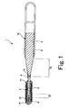
- Fig. 1 is a vertical sectional view showing an embodiment of the guide wire according to the present invention
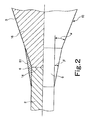
- Fig. 2 is a vertical sectional view showing in an enlarged form the vicinity of a joined portion of a wire body in the guide wire according to the present invention.
- the right side in Figs. 1 and 2 is referred to as "the proximal end (proximal side)", and the left side as “the distal end (distal side)”.
- the guide wire is schematically shown by shortening the guide wire in the longitudinal direction and exaggerating the guide wire in the transverse direction. Therefore, the ratio of size in the longitudinal direction to the size in the transverse direction is different from the real ratio.
- the guide wire 1 shown in Fig. 1 is a catheter guide wire used in the state of being inserted in the lumen of a catheter (inclusive of endoscope), and includes a wire body 10 and a spiral coil 4.
- the wire body 10 includes a first wire 2 disposed on the distal side, and a second wire 3 disposed on the proximal side of the first wire 2, the wires joined (connected) to each other by welding.
- the overall length of the guide wire 1 is not particularly limited, and is preferably about 200 to 5000 mm.
- the first wire 2 is composed of a filamentous material having flexibility or elasticity.
- the length of the first wire 2 is not particularly limited, and is preferably about 20 to 1000 mm.
- the first wire 2 has a portion having a constant outside diameter, and a tapered portion (gradually decreasing outside diameter portion) the outside diameter of which is gradually decreased in the distal direction.
- the latter portion may be present in one position or in two or more positions; in the embodiment shown in the drawings, a gradually decreasing outside diameter portion 15 is provided at one position.
- the rigidity (flexural rigidity, torsional rigidity) of the first wire 2 can be gradually reduced in the distal direction.
- the guide wire 1 can have good flexibility at its distal end portion, whereby trackability and safety in relation to a blood vessel or the like are enhanced, and kinking (sharp bending) or the like can be prevented from occurring.
- the taper angle (outside diameter reduction rate) of the gradually decreasing outside diameter portion 15 may be constant along the longitudinal direction of the guide wire 1, or may vary along the longitudinal direction at some portions. For example, portions with a comparatively larger taper angle (outside diameter reduction rate) and portions with a comparatively smaller taper angle may be alternately repeated a plurality of times.
- the portion on the proximal side of the first wire 2 (the portion on the proximal side relative to the gradually decreasing outside diameter portion 15) has an outside diameter which is constant up to the proximal end of the first wire 2.
- the distal end of the second wire 3 is joined (connected) by, for example, welding.
- the distal end of the second wire 3 may be joined by soldering or brazing.
- the second wire 3 is composed of a filamentous material having flexibility or elasticity.
- the length of the second wire 3 is not particularly limited, and is preferably about 20 to 4800 mm.
- a distal end portion of the second wire 3 is provided with a tapered portion 16 the outside diameter of which is gradually increased in the proximal direction from the distal end thereof (the distalmost end of the second wire 3).
- the outside diameter of the second wire 3 is substantially constant along the longitudinal direction of wire.
- the outside diameter of the distal end of the second wire 3 (the distal end of the tapered portion 16) is equal to the outside diameter of the proximal end of the first wire 2.
- the outside diameter of the distal end of the second wire 3 may be larger than the outside diameter of the proximal end of the first wire 2.
- the outside diameter of the distal end of the second wire 3 (the distal end of the tapered portion 16) may be smaller than the outside diameter of the proximal end of the first wire 2.
- the guide wire 1 is rich in flexibility at its first wire 2 on the distal side and comparatively high in rigidity at its second wire 3 on the proximal side, so that the flexibility at a distal end portion and the excellent steerability (pushability, torque response) can both be attained simultaneously.
- the tapered portion 16 provided at a distal end portion of the second wire 3 physical characteristics (particularly, elasticity) vary smoothly from the second wire 3 to the first wire 2, so that excellent pushability and torque response are displayed across a joined portion (joint surface) 14 between both wires 2 and 3, and kink resistance is also enhanced.
- the materials constituting the first wire and the second wire are not particularly limited; as the constituent materials, there can be used various metallic materials including, for example, stainless steels (e.g., all SUS steels such as SUS304, SUS303, SUS316, SUS316L, SUS316J1, SUS316JIL, SUS405, SUS430, SUS434, SUS444, SUS429, SUS430F, SUS302, etc.), piano wire, Ni-Ti base alloys, and cobalt alloys.
- stainless steels e.g., all SUS steels such as SUS304, SUS303, SUS316, SUS316L, SUS316J1, SUS316JIL, SUS405, SUS430, SUS434, SUS444, SUS429, SUS430F, SUS302, etc.
- piano wire e.g., all SUS steels such as SUS304, SUS303, SUS316, SUS316L, SUS316J1, SUS316JIL, SUS40
- Superelastic alloys are comparatively flexible, have restoring property, and are less susceptible to unremovable bend.
- the guide wire can have sufficient flexibility and restoring property against bend in its distal side portion, and is enhanced in the property of following up to a complicatedly curved or bent blood vessel, so that more excellent steerability can be obtained.
- unremovable bends are obviated by the restoring property of the first wire 2, so that a lowering in steerability can be prevented from occurring due to an unremovable bend imparted to the first wire 2 in use of the guide wire 1.
- the pseudo-elastic alloys include all shapes of tensile stress-strain curves, include those of which the transformation points such as As, Af, Ms, and Mf can be measured conspicuously as well as those of which the transformation points cannot be measured, and include all of those which are largely deformed (strained) under a stress and which can substantially return to the original shape thereof upon removal of the stress.
- the preferable composition of the superelastic alloys include Ni-Ti alloys such as Ni-Ti alloys containing 49-52 at % of Ni, Cu-Zn alloys containing 38.5-41.5 wt% of Zn, Cu-Zn-X alloys (X is at least one selected from the group including Be, Si, Sn, Al, and Ga) containing 1-10 wt% of X, and Ni-Al alloys containing 36-38 at % of Al.
- these alloys particularly preferred are the Ni-Ti based alloys.
- the superelastic alloys represented by Ni-Ti based alloys are excellent also in adhesion to resin coating layers 8 and 9 which will be described later.
- Cobalt alloys are high in elastic modulus when formed into wire, and have appropriate elastic limits. Therefore, a wire formed of a cobalt alloy is excellent in torque response, and is extremely highly resistant against buckling or the like.
- the cobalt alloy any alloys can be used that contain Co as a constituent element. Among these alloys, preferred are those containing Co as a principal constituent (Co-based alloys: alloys in which the Co content by weight is the highest of the contents of constituent elements), and more preferred are Co-Ni-Cr alloys. When an alloy with such a composition is used, the above-mentioned effects are displayed more conspicuously.
- an alloy with such a composition has a high elastic modulus, and can be cold formed when conditioned to have a high elastic limit, so that the alloy with its high elastic limit can be formed to have a reduced diameter while sufficiently preventing the generation of buckling, and can be provided with sufficient flexibility and rigidity for insertion thereof to a predetermined site.
- Co-Ni-Cr alloys preferred examples include alloys containing 28-50 wt% of Co, 10-30 wt% of Ni, 10-30 wt% of Cr, and the remainder of Fe, and alloys obtained by replacing a part of these alloys by other elements (substituent elements).
- the alloys contain the substituent elements, the alloys display intrinsic effects according to the kinds of the substituent elements.
- at least one selected from the group including Ti, Nb, Ta, Be, and Mo is contained as the substituent element, a further enhancement of the strength of the second wire 3 or the like can be contrived.
- the total content of the other elements (substituent elements) is preferably not more than 30 wt%.
- a part of Co, Ni, or Cr may be replaced by other element(s).
- a part of Ni may be replaced by Mn.
- a part of Cr may be replaced by Mo and/or W. This makes it possible to contrive a further improvement of elastic limit or the like.
- the Co-Ni-Cr alloys particularly preferred are those containing Mo, namely, Co-Ni-Cr-Mo alloys.
- composition of Co-Ni-Cr alloy include [1] 40 wt%Co-22wt%Ni-25wt%Cr-2wt%Mn-0.17wt%C-0.03wt%Be-remainder Fe, [2] 40wt%Co-15wt%Ni-20wt%Cr-2wt%Mn-7wt%Mo-0.15wt%C-0.03wt%Be-remainder Fe, [3] 42wt%Co-13wt%Ni-20wt%Cr-1.6wt%Mn-2wt%Mo-2.8wt%W-0.2wt%C-0.04wt%Be-remainder Fe, [4] 45wt%Co-21wt%Ni-18wt%Cr-1wt%Mn-4wt%Mo-1wt%Ti-0.02wt%C-0.3wt%Be-remainder Fe, and [5] 34wt%Co-21wt%Ni-14wt%Cr-0.5wt%
- the first wire 2 and the second wire 3 may be composed of different materials, but they may be composed of the same metallic material or of metallic materials of the same type (alloys in which the main metallic materials are the same). This ensures that the joint strength at the joined portion (welded portion) 14 is further higher, separation would not occur even when the outside diameter of the joined portion 14 is small, and excellent torque response and the like are displayed.
- the first wire 2 and the second wire 3 are each preferably formed of an Ni-Ti alloy.
- the first wire 2 and the second wire 3 are each preferably formed of a superelastic alloy. This makes it possible to secure excellent flexibility on the distal side relative to the tapered portion 16 of the wire body 10, and to secure sufficient rigidity (flexural rigidity, torsional rigidity) at a proximal side portion of the wire body 10.
- the guide wire 1 has excellent pushability and torque response, thereby securing good steerability, and at the same time, has good flexibility and restoring property on the distal side, whereby trackability and safety in relation to a blood vessel, the bile duct, and the pancreatic duct are enhanced.
- the first wire 2 and the second wire 3 are formed of different materials, it is preferable that the first wire 2 and the second wire 3 contain a common element.
- the first wire 2 is formed of an Ni-Ti alloy, and the second wire 3 is formed of a stainless steel, the common element being nickel. When both wires thus contain the common element, strength of welding therebetween is enhanced.
- the first wire 2 is formed of an Ni-Ti alloy, and the second wire 3 is formed of a Co-Ni-Cr alloy, the common element being nickel.
- the first wire 2 is formed of a material which is lower in elastic modulus than the material constituting the second wire 3.
- a coil 4 is disposed around a distal end portion of the first wire 2.
- the coil 4 is a member obtained by winding a filamentous material (thin wire) spirally, and is so disposed as to cover at least a distal side portion of the first wire 2.
- the distal side portion of the first wire 2 is inserted in a substantially central portion inside the coil 4.
- the distal side portion of the first wire 2 is inserted so as not to make contact with the inside surface of the coil 4.
- the joined portion 14 is located on the proximal side relative to the proximal end of the coil 4.
- the coil 4 has a configuration in which, in the absence of external force, a slight gap is left between the adjacent loops of the filamentous material wound spirally.
- a configuration may be adopted in which, in the absence of external force, the loops of the filamentous material wound spirally may be densely disposed with no gap therebetween.
- the coil 4 is preferably formed of a metallic material.
- the metallic material constituting the coil 4 include stainless steels, superelastic alloys, cobalt alloys, noble metals such as gold, platinum, tungsten, etc. and alloys containing noble metals (e.g., platinum-iridium alloy).
- the guide wire 1 can have a radiographically effective property, providing the merit that the guide wire 1 can be inserted into a living body while radioscopically confirming the position of a distal end portion thereof.
- the coil 4 may be formed of different materials on the distal side and on the proximal side thereof.
- the distal side of the coil 4 may be composed of a coil of a radiopaque material, while the proximal side of the coil 4 may be composed of a coil of a material (stainless steel or the like) comparatively transmitting X rays therethrough.
- the overall length of the coil 4 is not particularly limited, and is preferably about 5 to 500 mm.
- a proximal end portion and a distal end portion of the coil 4 are fixed to the first wire 2 by fixing materials 11 and 12, respectively.
- an intermediate portion (a position near the distal end) of the coil 4 is fixed to the first wire 2 by a fixing material 13.
- the fixing materials 11, 12, and 13 are each composed of a solder (brazing material).
- the fixing materials 11, 12, and 13 are not limited to solder, and may each be an adhesive.
- the method of fixing the coil 4 is not limited to the use of a fixing material; for example, welding may also be adopted.
- the distal end surface of the fixing material 12 is preferably rounded in shape.
- the first wire 2 is covered with the coil 4, and the contact area between the first wire 2 and a body lumen or the like is small. Therefore, sliding resistance in use can be reduced. Accordingly, the steerability of the guide wire 1 is further enhanced.
- a filamentous material which is circular in cross section is used to constitute the coil 4.
- this configuration is not limitative, and a filamentous material which has, for example, an elliptic or tetragonal (particularly, rectangular) shape or the like shape in section may also be used to constitute the coil 4.
- the first wire 2 and the second wire 3 constituting the guide wire body 10 are connected and fixed to each other by welding. This ensures that a high joint strength can be imparted to the joined portion (welded portion) 14 between the first wire 2 and the second wire 3 by a simple method. Therefore, in use of the guide wire 1, a torsional torque and pushing-in force applied from the side of the second wire 3 are securely transmitted to the first wire 2.
- the welding method for the first wire 2 and the second wire 3 is not particularly limited; examples of the welding method include friction pressure welding, butt resistance welding such as flash butt welding and upset butt welding, and welding by use of a laser. Among these welding methods, particularly preferred is the butt resistance welding, in view of its merit that a high joint strength can be obtained comparatively easily.
- the outside diameter of the proximal end of the first wire 2 is equal to the outside diameter of the distal end of the second wire 3 (the distal end of the tapered portion 16), so that the joined end faces of both wires 2 and 3 accord with each other in shape (preferably, circular shape). Therefore, when both wires 2 and 3 are abutted on each other for welding them, there is generated no step due to a difference in outside diameter.
- a metallic coating layer 6 is formed at the outer peripheral portion of the joined portion 14 of both the wires 2, 3. Now, the shape of the metallic coating layer 6 will be described.
- the distal side of the joined portion 14 is composed of the first wire 2 which is substantially constant in outside diameter
- the proximal side of the joined portion 14 is composed of the tapered portion 16 of the second wire 3 which is gradually increased in outside diameter in the proximal direction
- the metallic coating layer 6 is so formed as to range across the joined portion 14.
- the whole part or a part of the metallic coating layer 6 is composed of a tapered section 61 which is gradually increased in outside diameter in the proximal direction.
- the taper angle of the tapered portion 16 (the angle of the outer peripheral surface against the axis of wire) be ⁇ and let the taper angle of the tapered section 61 of the metallic coating layer 6 be ⁇ , then the relationship of ⁇ > ⁇ is established (see Fig. 2).
- the metallic coating layer 6 is formed in such a manner as to moderate the angular difference between the outer peripheral surface of a proximal end portion of the first wire 2 and the outer peripheral surface of the tapered portion 16 of the second wire 3.
- the sharp change in angle (change in rigidity) across the joined portion 14 can be moderated, and stress concentration on the jointed portion 14 can be excluded or alleviated.
- Physical properties, particularly, rigidity and elasticity vary smoothly from the second wire 3 to the first wire 2. Therefore, excellent pushability and torque response are displayed across the joined portion 14 of both the wires 2 and 3, and kink resistance thereat is also enhanced.
- the metallic coating layer 6 is composed of a solidified matter of a molten metal (melt) generated due to welding between both the wires 2 and 3. Therefore, the material constituting the metal coating layer 6 contains both of the constituent metals of the first wire 2 and the constituent metals of the second wire 3. Particularly, in the case where the first wire 2 and the second wire 3 are formed of the same metallic material or of metallic materials of the same type, as above-mentioned, the material constituting the metallic coating layer 6 also has a metallic composition similar to that or those of the wires 2 and 3.
- the metallic coating layer 6 preferably has been obtained by mechanically processing the solidified matter of the molten metal mentioned above. This makes it possible to let the metallic coating layer 6 have a desired shape and desired surface properties, and to further enhance the pushability, torque response, and kink resistance of the guide wire 1.
- the mechanical processing include grinding, polishing, and laser beam machining, which can be used either singly or in combination of two or more thereof.
- a chemical treatment such as etching may be applied in place of the mechanical processing or after the mechanical processing.
- the average thickness of the metallic coating layer 6 is not particularly limited.
- the average thickness is preferably about 1 to 100 ⁇ m, more preferably about 1 to 30 ⁇ m. If the thickness of the metallic coating layer 6 is too small, the functions of the metallic coating layer 6 mentioned above may fail to be displayed sufficiently. If the thickness is too large, on the other hand, the physical properties (rigidity, elasticity, etc.) may fail to vary smoothly between the first wire 2 and the second wire 3.
- the length of the metallic coating layer 6 in the longitudinal direction of wire is not particularly limited, and is preferably about 0.5 to 2.0 mm, more preferably about 0.5 to 1.0 mm.
- the metallic coating layer 6 as above is formed, for example, as follows.
- the proximal end of the first wire 2 and the distal end of the second wire 3 are put in press contact with each other while impressing a predetermined voltage between the first wire 2 and the second wire 3 by a butt welding machine, for example.
- a thin layer e.g., about 0.01 to 50 ⁇ m
- melt layer is solidified by cooling
- the joined portion 14 is formed, whereby the first wire 2 and the second wire 3 are firmly joined to each other.
- a protuberant portion increased in outside diameter is formed in a predetermined region including the joined portion 14 (e.g., a range of about 0.2 to 8 mm across the joined portion 14).
- the protuberant portion is formed through solidification of the molten matter of the first wire 2 and the second wire 3.
- the protuberant portion of the molten matter is appropriately removed for reshaping (ordering in shape), whereby the metallic coating layer 6 with a desired shape is obtained.
- the method of reshaping the protuberant portion include mechanical processings such as grinding, polishing, and laser beam machining, and chemical treatments such as etching. A chemical treatment may be carried out for the purpose of finishing or the like, after the mechanical processing is conducted.
- the outer peripheral surface of the metallic coating layer 6 can be made to be a substantially smooth surface.
- the metallic coating layer 6 has been described as one obtained by reshaping the molten and then solidified matter of the first wire 2 and the second wire 3, the metallic coating layer 6 is not limited to this one; for example, the molten and then solidified matter may be partly left in a projected form or be substantially removed and then another metallic coating may be formed on the surface thereof as above-mentioned.
- the another metallic coating can be formed by use of a material of the same type as the materials of the first wire 2 and the second wire 3.
- a plastic coating layer (a resin coating layer) may be formed, in place of the metallic coating layer 6.
- a configuration may be adopted in which the whole part or a part of the metallic coating layer 6 is coated with a coating layer of a plastic or the like.
- the tapered section 61 of the metallic coating layer 6 is gradually increased rectilinearly in outside diameter in the proximal direction, as shown in Fig. 2.
- the tapered section 61 may have a recessed surface or may have a projected surface.
- the wire body 10 has resin coating layers 8 and 9 which cover the whole part or a part of the outer peripheral surface (outside surface) of the wire body 10.
- the resin coating layers 8 and 9 are provided respectively at the outer peripheries of the first wire 2 and the second wire 3.
- These resin coating layers 8 and 9 can be formed for various purposes.
- One example of the purposes is to reduce the friction (sliding resistance) of the guide wire 1 and to enhance sliding property, thereby enhancing the steerability of the guide wire 1.
- the resin coating layer 8 or 9 may be provided so as to cover the outer periphery of the metal coating layer 6, unlike the case shown in the figure. This makes it possible to further moderate the variation in the outside diameter of the wire body 10 (variation in the taper angle), to further enhance the pushability, torque response, and kink resistance of the guide wire 1, and to enhance the steerability in moving the guide wire 1 in the longitudinal direction.
- the resin coating layer 8 and 9 are each preferably formed of a material capable of reducing friction as will be described below. This ensures that the frictional resistance (sliding resistance) between the guide wire 1 and the inside wall of a catheter used with the guide wire 1 is reduced, whereby slidability is enhanced, and the steerability of the guide wire 1 in the catheter is enhanced.
- kinking (sharp bending) and torsion of the guide wire 1 particularly, kinking and torsion in the vicinity of the joined portion 14 can be prevented more assuredly from occurring when the guide wire 1 is moved and/or rotated in the catheter.
- Examples of the material capable of reducing friction include polyolefins such as polyethylene, polypropylene, etc., polyvinyl chloride, polyesters (PET, PBT, etc.), polyamides, polyimides, polyurethane, polystyrene, polycarbonate, silicone resins, fluororesins (PTFE, ETFE, etc.), and composite materials thereof.
- polyolefins such as polyethylene, polypropylene, etc., polyvinyl chloride, polyesters (PET, PBT, etc.), polyamides, polyimides, polyurethane, polystyrene, polycarbonate, silicone resins, fluororesins (PTFE, ETFE, etc.), and composite materials thereof.
- the wire body 10 can be coated with a resin material being in a heated state, by such a method as baking and spraying. This ensures that the adhesion of the resin coating layers 8 and 9 to the wire body 10 will be particularly excellent.
- the resin coating layers 8 and 9 are each composed of a silicone resin (or a composite material containing the same)
- the resin coating layers 8 and 9 adhered assuredly and firmly to the wire body 10 can be formed, without heating at the time of forming the resin coating layers 8 and 9 (coating the wire body 10 with the resin).
- the resin coating layers 8 and 9 are each composed of a silicone resin (or a composite material containing the same)
- a reaction-curable type material or the like can be used, so that the resin coating layers 8 and 9 can be formed at room temperature. With the resin coating layers 8 and 9 thus formed at room temperature, the coating can be carried out easily, and the guide wire can be operated in the condition where the joint strength between the first wire 2 and the second wire 3 at the jointed portion 14 is maintained sufficiently.
- the resin coating layers 8 and 9 can also be provided for the purpose of enhancing safety at the time of inserting the guide wire 1 into a blood vessel or the like.
- the resin coating layers 8 and 9 are each preferably formed of a material rich in flexibility (soft material, elastic material).
- Examples of the material rich in flexibility include polyolefins such as polyethylene, polypropylene, etc., polyvinyl chloride, polyesters (PET, PBT, etc.), polyamides, polyimides, polyurethane, polystyrene, silicone resins, thermoplastic elastomers such as polyurethane elastomer, polyester elastomers, polyamide elastomers, etc., various rubber materials such as latex rubber, silicone rubber, etc., and composite materials containing two or more of these materials in combination.
- polyolefins such as polyethylene, polypropylene, etc., polyvinyl chloride, polyesters (PET, PBT, etc.), polyamides, polyimides, polyurethane, polystyrene, silicone resins, thermoplastic elastomers such as polyurethane elastomer, polyester elastomers, polyamide elastomers, etc., various rubber materials such as latex rubber, silicone rubber, etc., and composite
- the resin coating layers 8 and 9 are each composed of a thermoplastic elastomer or a rubber among the above-mentioned materials, so that damage to the inside wall of a blood vessel or the like can be prevented more assuredly from occurring at the time of inserting the guide wire 1 into the blood vessel or the like; thus, safety is extremely high.
- Each of the resin coating layers 8 and 9 as above may be a laminate body composed of two or more layers.
- the resin coating layers 8 and the resin coating layer 9 may be composed of the same material or be composed of different materials.
- a configuration can be adopted in which the resin coating layer 8 located on the distal side of the guide wire 1 is formed of the above-mentioned material rich in flexibility (soft material, elastic material), and the resin coating layer 9 located on the proximal side of the guide wire 1 is formed of the above-mentioned material capable of reducing friction.
- This configuration makes it possible to achieve both enhancement of slidability (steerability) and enhancement of safety, simultaneously.
- each of the resin coating layers 8 and 9 is not particularly limited, and is appropriately set in consideration of the purpose(s), the constituent material(s), the forming method(s), and the like of the resin coating layers 8 and 9.
- the resin coating layers 8 and 9 each preferably has a thickness (on average) of about 1 to 100 ⁇ m, more preferably about 1 to 30 ⁇ m.
- the thickness of each of the resin coating layers 8 and 9 is too small, the purpose(s) of forming the resin coating layers 8 and 9 may not be fulfilled sufficiently, and exfoliation of the resin coating layers 8, 9 may occur.
- the thickness of each of the resin coating layers 8 and 9 is too large, the physical properties of the wire body 10 may be influenced, and exfoliation of the resin coating layers 8, 9 may occur.
- the outer peripheral surface (surface) of the wire body 10 may be subjected to a treatment (surface roughening, chemical treatment, heat treatment, or the like) for enhancing the adhesion of the resin coating layers 8 and 9 thereto, or may be provided thereon with an intermediate layer capable of enhancing the adhesion of the resin coating layers 8 and 9.
- a treatment surface roughening, chemical treatment, heat treatment, or the like
- the outside surface of at least a distal end portion of the guide wire 1 is coated with a hydrophilic material.
- the outer peripheral surface of the guide wire 1 in the range from the distal end of the guide wire 1 to the vicinity of the proximal end of the tapered portion 16 is coated with a hydrophilic material. This ensures that the hydrophilic material generate lubricity by being wetted, whereby the friction (sliding resistance) on the guide wire 1 is reduced, and slidability is enhanced. Therefore, the steerability of the guide wire 1 is enhanced.
- hydrophilic material examples include cellulose polymeric substances, polyethylene oxide polymeric substances, maleic anhydride polymeric substances (for example, maleic anhydride copolymers such as methyl vinyl ether-maleic anhydride copolymer), acrylamide polymeric substances (for example, polyacrylamide, polyglycidyl methacrylate-dimethyl acrylamide (PGMA-DMAA) block copolymer), water-soluble nylon, polyvinyl alcohol, and polyvinyl pyrrolidone.
- maleic anhydride polymeric substances for example, maleic anhydride copolymers such as methyl vinyl ether-maleic anhydride copolymer
- acrylamide polymeric substances for example, polyacrylamide, polyglycidyl methacrylate-dimethyl acrylamide (PGMA-DMAA) block copolymer
- water-soluble nylon for example, polyvinyl alcohol, and polyvinyl pyrrolidone.
- Such a hydrophilic material in many cases, displays lubricity due to wetting (water absorption), thereby reducing the frictional resistance (sliding resistance) between the guide wire 1 and the inside wall of a catheter used with the guide wire 1. This enhances the slidability of the guide wire 1, and further enhances the steerability of the guide wire 1 in the catheter.
- Fig. 3 is a vertical sectional view showing another embodiment of the guide wire according to the present invention.
- the guide wire shown in Fig. 3 will be described, in which the descriptions of the same items as those of the guide wire shown in Figs. 1 and 2 will be omitted, and description will be centered on the differences between the two guide wires.
- the right side in Fig. 3 is referred to as "the proximal end (proximal side)", and the left side as “the distal end (distal side)”.
- the guide wire is shown schematically by shortening the guide wire in the longitudinal direction and exaggerating the guide wire in the transverse direction, so that the ratio between the longitudinal size and the transverse size in the figure is different from the real ratio.
- the guide wire 1 shown in Fig. 3 is the same as the guide wire 1 shown in Figs. 1 and 2, except for not having the coil 4.
- the guide wire 1 shown in Fig. 3 has a wire body 10 in which a first wire 2 disposed on the distal side and a second wire 3 disposed on the proximal side of the first wire 2 are joined (connected) to each other by welding, and the outer peripheral portion of the joined portion 14 between the first wire 2 and the second wire 3 is covered with a metallic coating layer 6.
- a distal side portion (the outer peripheral surface of the first wire 2) and a proximal side portion (the outer peripheral surface of the second wire 3) of the wire body 10 are covered respectively with resin coating layers 8 and 9.
- the resin coating layer 8 located on the distal side of the guide wire 1 is preferably formed of the above-mentioned material rich in flexibility (soft material, elastic material), while the resin coating layer 9 located on the proximal side of the guide wire 1 is preferably formed of the above-mentioned material capable of reducing friction.
- the resin coating layer 8 is formed of polyurethane
- the resin coating layer 9 is formed of a fluoro-resin (PTFE, ETFE, or the like).
- a proximal end portion of the resin coating layer 8 is terminated on the distal side relative to the proximal end of the first wire 2.
- a distal end portion of the resin coating layer 9 is terminated on the proximal side relative to the distal end of the second wire 3.
- the proximal end portion of the first wire 2 and the distal end portion of the second wire 3 are exposed, with the joined portion 14 located therebetween.
- the proximal end portion of the resin coating layer 8 and the first wire 2 are different in color, so that the motions of the guide wire can be recognized.
- the outside diameter of the resin coating layer 8 is equal to the outside diameter of the resin coating layer 9.
- the resin coating layer 8 covers the distal end of the first wire 2 so as not to expose the distal end; moreover, the distal end of the resin coating layer 8 is preferably rounded in shape. This makes it possible to prevent more effectively the damages to the inside wall of a body lumen such as a blood vessel at the time of inserting the guide wire 1 into the body lumen, and thereby to enhance safety.
- a filler (particles) of a contrast material (the above-mentioned radiopaque material) may be mixed, so as to constitute a radioscopically effective (contrast) portion.
- the outside surface of at least a distal end portion of the guide wire 1 is preferably coated with a hydrophilic material.
- the outer peripheral surface of the guide wire 1 in the range from the distal end of the guide wire 1 to the vicinity of the proximal end of the tapered portion 16 is coated with a hydrophilic material. This ensures that the hydrophilic material generates lubricity by being wetted, whereby the friction (sliding resistance) on the guide wire 1 is reduced, and slidability is enhanced. Therefore, the steerability of the guide wire 1 is enhanced.
- the coating of the hydrophilic material may be formed only on a part of the outside surface of the resin coating layer 8 or the whole area of the outside surface.
- specific examples of the hydrophilic material are the same as above-mentioned.
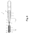
- Fig. 4 is a vertical sectional view showing a further embodiment of the guide wire according to the present invention
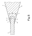
- Fig. 5 is a vertical sectional view showing in an enlarged form the vicinity of a joined portion of a wire body in the guide wire according to the present invention.
- the right side in Figs. 4 and 5 is referred to as "the proximal end (proximal side)", and the left side as “the distal end (distal side)”.
- the guide wire is schematically shown by shortening the guide wire in the longitudinal direction and exaggerating the guide wire in the transverse direction, so that the ratio between the longitudinal size and the transverse size is different from the real ratio.
- the guide wire 1 shown in Fig. 4 is a catheter guide wire used in the state of being inserted in the - lumen of a catheter (inclusive of an endoscope), and includes a wire body 10 and a spiral coil 4.
- the wire body 10 includes a first wire 2 disposed on the distal side and a second wire 3 disposed on the proximal side of the first wire 2, which are joined (connected) to each other.
- the first wire 2 and the second wire 3 can be joined by welding, soldering or brazing.
- the overall length of the guide wire 1 is not particularly limited, and is preferably about 200 to 5000 mm.
- the first wire 2 is composed of a filamentous material having flexibility or elasticity.
- the length of the first wire 2 is not particularly limited, and is preferably about 20 to 1000 mm.
- the first wire 2 has a portion which is constant in outside diameter, and a tapered portion (gradually decreasing outside diameter portion) which is gradually decreased in outside diameter in the distal direction.
- the latter portion may be provided at one position or at two or more positions; in the embodiment shown in the figure, the gradually decreasing outside diameter portion 15 is provided at one position.
- the rigidity (flexural rigidity, torsional rigidity) of the first wire 2 can be gradually reduced in the distal direction.
- the guide wire 1 is provided with good flexibility at its distal end portion, whereby trackability and safety in relation to a blood vessel or the like are enhanced, and sharp bending and the like can be prevented.
- the taper angle (the decreasing rate of the outside diameter) of the gradually decreasing outside diameter portion 15 may be constant along the longitudinal direction of wire, or may vary along the longitudinal direction at some part. For example, portions where the taper angle (the decreasing rate of the outside diameter) is comparatively large and portions where the taper angle is comparatively small may be alternately formed repeatedly a plurality of times.
- a proximal side portion (a portion on the proximal side relative to the gradually decreasing outside diameter portion 15) of the first wire 2 is constant in outside diameter up to the proximal end of the first wire 2.
- the distal end of the second wire 3 is joined (connected) to the proximal end of the first wire 2.
- the second wire 3 is composed of a filamentous material having flexibility or elasticity.
- the length of the second wire 3 is not particularly limited, and is preferably about 20 to 4800 mm.
- the second wire 3 is provided at its distal end portion with the tapered portion 16 which is gradually increased in outside diameter in the proximal direction from the distal end thereof (the distalmost end of the second wire 3).
- the outside diameter is substantially constant along the longitudinal direction of wire.
- the ratio D1/D2 is preferably about 0.2 to 0.98, more preferably about 0.5 to 0.9. With the ratio D1/D2 set in such a range, it is possible to secure the area of the joined portion 14 between the first wire 2 and the second wire 3, thereby obtaining a sufficient joint strength, and to make the first wire 2 rich in flexibility.
- the average outside diameter of the first wire 2 is smaller than the average outside diameter of the second wire 3. This ensures that the guide wire 1 is rich in flexibility at the first wire 2 on the distal side, and is comparatively high in rigidity at the second wire 3 on the proximal side, so that the flexibility at the distal end portion and the excellent steerability (pushability, torque response, etc.) can both be attained simultaneously.
- the material(s) constituting the first wire 2 and the second wire 3 is not particularly limited.
- the material(s) include various metallic materials such as stainless steels (all kinds of SUS, namely, SUS304, SUS303, SUS316, SUS316L, SUS316J1, SUS316J1L, SUS405, SUS430, SUS434, SUS444, SUS429, SUS430F, SUS302, et.), piano wire, Ni-Ti base alloys, and cobalt alloys.
- Ni-Ti base alloys particularly preferred are Ni-Ti base alloys, and more preferred are Ni-Ti base pseudo-elastic alloys (inclusive of Ni-Ti base superelastic alloys).
- the first wire 2 and the second wire 3 may be formed of different materials.
- Wires 2 and 3 may be formed of the same metallic material or formed of metallic materials of the same type (alloys in which the principal metallic materials are the same). This ensures that the joint strength at the joined portion (welded portion) 14 is further enhanced. Even when the joined portion 14 is small in outside diameter, separation would not occur, and excellent torque response and the like are displayed.
- the first wire 2 and the second wire 3 are each formed of an Ni-Ti alloy.
- the first wire 2 and the second wire 3 are each formed of a superelastic alloy. This makes it possible to secure excellent flexibility on the distal side relative to the tapered portion 16 of the wire body 10, and to secure sufficient rigidity (flexural rigidity, torsional rigidity) at the proximal side portion of the wire body 10.
- the guide wire 1 acquires excellent pushability and torque response, thereby obtaining good steerability, and, simultaneously, acquires good flexibility and restoring property on the distal side, whereby trackability and safety in relation to blood vessels, the bile duct, and the pancreatic duct are enhanced.
- the first wire 2 and the second wire 3 are formed of different materials
- the first wire 2 and the second wire 3 preferably have a common element.
- the first wire 2 is formed of an Ni-Ti alloy
- the second wire 3 is formed of a stainless steel, the common element being nickel. Due to the presence of the common element, the strength of weld is enhanced.
- the first wire 2 is formed of an Ni-Ti alloy
- the second wire 3 is formed of a Co-Ni-Cr alloy, the common element being nickel. It is preferable that the first wire 2 is formed of a material lower in elastic modulus than the material of the second wire 3.
- the coil 4 is disposed around a distal end portion of the first wire 2.
- the coil 4 is a member obtained by winding a filamentous material (thin wire) spirally, and is so disposed as to cover at least a distal side portion of the first wire 2.
- the distal side portion of the first wire 2 is inserted to a substantially central portion inside the coil 4.
- the distal side portion of the first wire 2 is inserted so as not to make contact with the inside surface of the coil 4.
- the joined portion 14 is located on the proximal side relative to the proximal end of the coil 4.
- the coil 4 has a slight gap between the adjacent loops of the spirally wound filamentous material, in the absence of external forces.
- a configuration may be adopted in which, unlike the configuration shown in the figure, the loops of the spirally wound filamentous material are densely disposed with no gaps therebetween, in the absence of external forces.
- the coil 4 is preferably formed of a metallic material.
- the metallic material constituting the coil 4 include stainless steels, superelastic alloys, cobalt alloys, noble metals such as gold, platinum, tungsten, etc. and alloys containing a noble metal (e.g., platinum-iridium alloys).
- the guide wire 1 acquires a radioscopically effective (contrast) property, with the result of the merit that the guide wire 1 can be inserted into a living body while radioscopically confirming the position of a distal end portion of the guide wire 1.
- the coil 4 may be formed of different materials on the distal side and on the proximal side.
- the distal side is composed of a coil of a radiopaque material
- the proximal side is composed of a coil of a comparatively X ray transmitting material (stainless steel or the like).
- the overall length of the coil 4 is not particularly limited, and is preferably about 5 to 500 mm.
- a proximal end portion and a distal end portion of the coil 4 are fixed to the first wire 2 by fixing materials 11 and 12, respectively.
- an intermediate portion (the position near the distal end) of the coil 4 is fixed to the first wire 2 by a fixing material 13.
- the fixing materials 11, 12, and 13 are each composed of a solder (brazing material).
- each of the fixing materials 11, 12, and 13 is not limited to the solder, and may be an adhesive.
- the method of fixing the coil 4 is not limited to the use of the fixing material; for example, welding may also be adopted.
- the distal end face of the fixing material 12 is preferably rounded in shape.
- the first wire 2 has a small contact area because it is covered with the coil 4, whereby sliding resistance can be reduced, so that the steerability of the guide wire 1 is further enhanced.
- the coil 4 is formed by use of the filamentous material circular in cross section in the case of this embodiment, this configuration is not limitative, and the filamentous material may have an elliptic shape, a tetragonal (particularly, rectangular) shape, or the like shape in section.
- the first wire 2 and the second wire 3 constituting the guide wire body 10 are connected and fixed to each other by welding. This makes it possible to obtain a high joint strength at the joined portion (welded portion) 14 between the first wire 2 and the second wire 3, so that a torsional torque and a pushing-in force from the second wire 3 can be assuredly transmitted to the first wire 2 in use of the guide wire 1.
- the welding method for the first wire 2 and the second wire 3 is not particularly limited, and examples of the welding method include friction pressure welding, butt resistance welding such as flash butt welding and upset butt welding, and welding by use of a laser.
- the butt resistance welding particularly preferred is the butt resistance welding, since it is easy to carry out and provides a high joint strength.
- An axis line of the first wire 2 and an axis line of the second wire 3 are preferably overlapped as straight as a line.
- an axis line of the distal member and an axis line of the proximal member are preferably joined to be located as straight line.
- an axis line of the distal wire and an axis line of the proximal wire are preferably overlapped as straight line.
- a guide wire may include a distal wire with an axis line, a proximal wire with an axis line and a middle wire disposed between the distal wire and the proximal wire with an axis line. At least two of three axis lines may be overlapped as straight line. Preferably the axis of the distal wire, the axis line of the middle wire and the axis line of the proximal wire are preferably overlapped one another as straight line.
- a guide wire including a distal wire having a proximal end face and a proximal wire having a distal end face
- the proximal end face of the distal wire may be welded to the distal end face of the proximal wire.
- An offset distance between a center point of a proximal end face of the distal wire and a center point of a distal end face of the proximal wire, through a welded portion with the distal wire and the proximal wire are preferably within 10 percent, more preferably within 5 percent by diameter.
- the outside diameter D1 at the proximal end of the first wire 2 is smaller than the outside diameter D2 at the distal end (the distal end of the tapered portion 16) of the second wire 3; therefore, when the wires 2 and 3 are abutted on each other for welding, a step 5 is generated due to the difference between the outside diameter D2 and the outside diameter D1 (hereinafter referred to as "the outside diameter difference").
- a metallic coating layer 6 such as to bury the step 5 is formed on the outer peripheral portion of the joined portion 14 between the wires 2 and 3. Now, the shape of the metallic coating layer 6 will be described.
- the distal side of the joined portion 14 is composed of the first wire 2 which is substantially constant in outside diameter
- the proximal side of the joined portion 14 is composed of the tapered portion 16 of the second wire 3 which is gradually increased in outside diameter in the proximal direction
- the metallic coating layer 6 is so formed as to bury the step 5 generated due to the outside diameter difference between the proximal end of the first wire 2 and the distal end of the tapered portion 16.
- the metallic coating layer 6 has a tapered section 61 which is gradually decreased in outside diameter from the proximal end toward the distal end thereof.
- substantially the whole part of the metallic coating layer 6 is composed of the tapered section 61, but the tapered section 61 may be formed partly.
- Such a metallic coating layer 6 is gradually decreased in thickness in the distal direction, at the tapered section 61. Particularly, in Figs. 5 to 7, the thickness of the metallic coating layer 6 is reduced rectilinearly in the distal direction.
- the relationship of 0.5 ⁇ ⁇ / ⁇ ⁇ 2 is fulfilled. More preferably, the relationship of 0.75 ⁇ ⁇ / ⁇ ⁇ 1.25 is fulfilled, where ⁇ is the taper angle of the tapered section 61 of the metallic coating layer 6 (the angle of the outer peripheral surface against the axis of the wire body 10), and ⁇ is the taper angle of the tapered portion 16 of the second wire 3.
- ⁇ has a value comparatively approximate to the value of ⁇ , so that the variation (decrease) rate of outside diameter from the tapered portion 16 of the second wire 3 to the first wire 2 is reduced. Therefore, the physical properties, particularly, elasticity varies smoothly from the second wire 3 to the first wire 2. As a result, excellent pushability and torque response are displayed across the joined portion (joint surface) between the wires 2 and 3, and kink resistance thereat is also enhanced.
- the metallic coating layer 6 is so formed as to moderate the angle difference between the outer peripheral surface of a proximal end portion of the first wire 2 and the outer peripheral surface of the tapered portion 16 of the second wire 3, so that the above-mentioned effects are displayed more conspicuously, which is favorable.
- the metallic coating layer 6 is composed of a solidified matter of a molten metal (melt) generated upon welding of the wires 2 and 3. Therefore, the material constituting the metallic coating layer 6 contains at least one of the constituent metal of the first wire 2 and the constituent metal of the second wire 3, and ordinarily contain both of the constituent metals. Particularly, where the first wire 2 and the second wire 3 are formed of the same metallic material or formed of metallic materials of the same type, the material constituting the metallic coating layer 6 also has a metallic composition similar to that (those) of the wires 2 and 3.
- the metallic coating layer 6 has been reshaped, for example, into the shapes shown in Figs. 5 to 7, by mechanically processing the solidified matter of the molten metal.
- This makes it possible to set the metallic coating layer 6 to have a desired shape or surface properties, and to further enhance the pushability, torque response, and kink resistance of the guide wire 1.
- the mechanical processing include grinding, polishing, laser beam machining, etc., which can be performed singly or in combination of two or more of them.
- a chemical treatment such as etching may be carried out, in place of the mechanical processing or after the mechanical processing.
- the metallic coating layer 6 is preferably made to have a stepless continuous surface by such a reshaping.
- the outer peripheral surface of the proximal end portion of the metallic coating layer 6 and the outer peripheral surface of the distal end portion of the tapered portion 16 of the second wire 3 constitute a stepless continuous surface (see Fig. 5).
- the average thickness of the metallic coating layer 6 is not particularly limited, and is preferably about 2 to 300 ⁇ m, more preferably about 1 to 200 ⁇ m, and further preferably about 1 to 100 ⁇ m. If the step 5 is too large, the thickness of the metallic coating layer 6 tends to increase, and the physical properties (rigidity, elasticity, etc.) may not vary smoothly between the first wire 2 and the second wire 3 in the case where the wires 2 and 3 are formed of different materials. On the other hand, when the thickness of the metallic coating layer 6 is too small, the above-mentioned functions of the metallic coating layer 6 may not be displayed sufficiently.
- the length of the metallic coating layer 6 is not particularly limited, and is preferably about 0.5 to 2.0 mm, more preferably about 0.5 to 1.0 mm.
- Such a metallic coating layer 6 as above is formed, for example, as follows.
- the proximal end of the first wire 2 and the distal end of the second wire 3 are made to make press contact with each other while impressing a predetermined voltage on the first wire 2 and the second wire 3 by a butt welding machine, for example.
- a thin (for example, about 0.01-50 ⁇ m thick) melt layer is formed at the contact portion, and when the melt layer is solidified by cooling, the joined portion 14 is formed, whereby the first wire 2 and the second wire 3 are firmly joined to each other.
- a molten matter is collected in the inside of the step 5 (for example, in the region in the range of about 0.2 to 8 mm in the distal direction from the joined portion 14), and the molten matter is solidified, to form a protuberant portion as if the outside diameter of the first wire 2 were increased.
- the protuberant portion is obtained through solidification of the molten matter(s) of the first wire 2 and/or the second wire 3.
- the protuberant portion of the molten matter(s) is formed in excess of the outside diameter D2. Therefore, the protuberant portion is appropriately removed or reshaped (ordered in shape), whereby the metallic coating layer 6 having a desired shape as shown in Figs. 5 to 7 is obtained.
- the reshaping method include mechanical proceessings such as grinding, polishing, laser beam machining, etc., and chemical treatments such as etching, etc., applied to the protuberant portion. A chemical treatment may be carried out for the purpose of finishing or the like, after the mechanical processing is conducted.
- the outer peripheral surface of the metallic coating layer 6 can be made to be a substantially smooth surface.
- the tapered section 61 of the metallic coating layer 6 is gradually increased rectilinearly in outside diameter in the proximal direction from the distal end thereof as shown in Fig. 5, the tapered section 61 may have a recessed surface or may have a projected surface.
- the metallic coating layer 6 may be wholly or partly covered with a coating layer of a resin or the like as will be described later.
- the tapered portion 16 of the second wire 3 is provided before joining to the first wire 2 in the above embodiment, no tapered portion of the second wire 3 may be provided before joining and the tapered portion 16 may be formed after joining.
- the second wire 3 having a constant diameter distal portion and the first wire 2 having a constant and lager diameter proximal portion than the constant diameter distal portion are prepared.
- the proximal end of the first wire 2 and the distal end of the second wire 3 are joined together as above.
- a thin melt layer is formed at the contact portion, and when the melt layer is solidified by cooling, the joined portion 14 is formed, whereby the first wire 2 and the second wire 3 are firmly joined to each other.
- a molten matter is collected in the inside of the step, and the molten matter is solidified, to form a protuberant portion as if the outside diameter of the first wire 2 were increased.
- the protuberant portion is obtained through solidification of the molten matter(s) of the first wire 2 and/or the second wire 3.
- a distal portion of the second wire 3 is grinded with a predetermined angle to be gradually decreased in outside diameter in the distal direction.
- the protuberant portion is also grinded with the same angle as the predetermined angle to be the metallic coating layer 6 shown as Fig.5.
- the protuberant portion may be grinded with a larger angle than the predetermined angle shown as Fig.6.
- the protuberant portion may be grinded with the smaller angle than the predetermined angle shown as Fig.7.
- the metallic coating layer 6 is made to have a stepless continuous surface by such a reshaping.
- the wire body 10 has resin coating layers 8 and 9 covering the whole part or a part of the outer peripheral surface (outside surface) thereof.
- the resin coating layers 8 and 9 are provided respectively at the outer peripheries of the first wire 2 and the second wire 3.
- These resin coating layers 8 and 9 may be formed for various purposes.
- One example of the purposes is to reduce the friction (sliding resistance) on the guide wire 1, and to enhance slidability, thereby enhancing the steerability of the guide wire 1.
- the resin coating layer 8 or 9 may be so provided as to cover the outer periphery of the metallic coating layer 6. This makes it possible to further moderate the outside diameter variation (variation rate of taper angle) of the wire body 10, to further enhance the pushability, torque response, and kink resistance of the guide wire 1, and to enhance the steerability in moving the guide wire 1 in the longitudinal direction.
- each of the resin coating layers 8 and 9 is preferably formed of a material capable of reducing friction which will be described below. This ensures that the frictional resistance (sliding resistance) between the guide wire 1 and the inside wall of a catheter used together with the guide wire 1, whereby slidability is enhanced, and the steerability of the guide wire 1 in the catheter is further enhanced.
- the sliding resistance on the guide wire 1 reduced, it is possible to prevent more assuredly the kinking (sharp bending) or torsion of the guide wire 1, particularly kinking or torsion in the vicinity of the joined portion 14, from occurring when the guide wire 1 is moved and/or rotated in the catheter.
- Examples of the material capable of reducing friction include polyolefins such as polyethylene, polypropylene, etc., polyvinyl chloride, polyesters (PET, PBT, etc.), polyamides, polyimides, polyurethane, polystyrene, polycarbonate, silicone resins, fluororesins (PTFE, ETFE, etc.), and composite materials of them.
- polyolefins such as polyethylene, polypropylene, etc., polyvinyl chloride, polyesters (PET, PBT, etc.), polyamides, polyimides, polyurethane, polystyrene, polycarbonate, silicone resins, fluororesins (PTFE, ETFE, etc.), and composite materials of them.
- a resin material may be applied to the wire body 10 in a heated state, by such a method as baking and spraying. This makes it possible to obtain a particularly excellent adhesion between the wire body 10 and the resin coating layers 8, 9.
- the resin coating layers 8 and 9 are each composed of a silicone resin (or a composite material containing the same)
- resin coating layers 8 and 9 adhered assuredly and firmly to the wire body 10 can be formed, without heating, at the time of forming the resin coating layers 8 and 9 (coating the wire body 10 therewith).
- a reaction-curable type material or the like can be used, so that the formation of the resin coating layers 8 and 9 can be carried out at room temperature. With the resin coating layers 8 and 9 thus formed at room temperature, the coating can be carried out easily, and the guide wire can be operated in the condition where the joint strength between the first wire 2 and the second wire 3 at the jointed portion 14 is maintained sufficiently.
- the resin coating layers 8 and 9 can also be provided for enhancing safety at the time of inserting the guide wire 1 into a blood vessel or the like.
- the resin coating layers 8 and 9 are each preferably formed of a material rich in flexibility (soft material, elastic material).
- Examples of the material rich in flexibility include polyolefins such as polyethylene, polypropylene, etc., polyvinyl chloride, polyesters (PET, PBT, etc.), polyamides, polyimides, olyurethane, polystyrene, silicone resins, thermoplastic elastomers such as polyurethane elastomer, polyester elastomers, polyamide elastomers, etc., various rubber materials such as latex rubber, silicone rubber, etc., and composite materials containing two or more of these materials in combination.
- polyolefins such as polyethylene, polypropylene, etc., polyvinyl chloride, polyesters (PET, PBT, etc.), polyamides, polyimides, olyurethane, polystyrene, silicone resins, thermoplastic elastomers such as polyurethane elastomer, polyester elastomers, polyamide elastomers, etc., various rubber materials such as latex rubber, silicone rubber, etc
- the flexibility of the distal end portion of the guide wire 1 is further enhanced, so that damages to the inside wall of a blood vessel or the like can be prevented more assuredly from occurring at the time of inserting the guide wire 1 into the blood vessel or the like. Therefore, extremely high safety is attained.
- Each of the resin coating layers 8 and 9 as above may be a laminate of two or more layers.
- the resin coating layers 8 and 9 may be formed of the same material, or may be formed of different materials.
- a configuration may be adopted in which the resin coating layer 8 located on the distal side of the guide wire 1 is formed of the above-mentioned material rich in flexibility (soft material, elastic material), and the resin coating layer 9 located on the proximal side of the guide wire 1 is formed of the above-mentioned material capable of reducing friction. This makes it possible to simultaneously achieve both enhancement of slidability (steerability) and enhancement of safety.
- each of the resin coating layers 8 and 9 is not particularly limited, and is appropriately set by taking into account the purpose(s), the constituent material(s), the forming method(s), and the like of the resin coating layers 8 and 9.
- the thickness (on average) of each of the resin coating layers 8 and 9 is preferably about 1 to 100 ⁇ m, more preferably about 1 to 30 ⁇ m. If the resin coating layers 8 and 9 are too thin, the purpose(s) of the resin coating layers 8 and 9 may not be displayed sufficiently, and exfoliation of the resin coating layers 8 and 9 may occur. On the other hand, if the resin coating layers 8 and 9 are too thick, the physical properties of the wire body 10 may be influenced, and exfoliation of the resin coating layers 8 and 9 may occur.
- the outer peripheral surface (surface) of the wire body 10 may be subjected to a treatment (surface roughening, chemical treatment, heat treatment, or the like) for enhancing the adhesion of the resin coating layers 8 and 9 thereto, and may be provided thereon with an intermediate layer for enhancing the adhesion of the resin coating layers 8 and 9 thereto.
- a treatment surface roughening, chemical treatment, heat treatment, or the like
- the outside surface of at least a distal end portion of the guide wire 1 is preferably coated with a hydrophilic material.
- a coating of a hydrophilic material is provided on the outer peripheral surface of the guide wire 1 in the range from the distal end of the guide wire 1 to the vicinity of the proximal end of the tapered portion 16 of the second wire 3. This ensures that the hydrophilic material generates lubricity by being wetted, whereby the friction (sliding resistance) on the guide wire 1 is reduced, and slidability is enhanced. Therefore, the steerability of the guide wire 1 is enhanced.
- hydrophilic material examples include cellulose polymeric substances, polyethylene oxide polymeric substances, maleic anhydride polymeric substances (e.g., maleic anhydride copolymers such as methyl vinyl ether-maleic anhydride copolymer), acrylamide polymeric substances (e.g., polyacrylamide, polyglycidyl methacrylate-dimethyl acrylamide (PGMA-DMAA) block copolymer, water-soluble nylon, polyvinyl alcohol, and polyvinyl pyrrolidone.
- maleic anhydride polymeric substances e.g., maleic anhydride copolymers such as methyl vinyl ether-maleic anhydride copolymer
- acrylamide polymeric substances e.g., polyacrylamide, polyglycidyl methacrylate-dimethyl acrylamide (PGMA-DMAA) block copolymer
- PGMA-DMAA polyglycidyl methacrylate-dimethyl acrylamide
- such a hydrophilic material as above displays lubricity due to wetting (water absorption), thereby reducing the frictional resistance (sliding resistance) between the guide wire 1 and the inside wall of a catheter used together with the guide wire 1.
- the slidability of the guide wire 1 is enhanced, and the steerability of the guide wire 1 in the catheter becomes more favorable.
- Fig. 8 is a vertical sectional view showing yet another embodiment of the guide wire according to the present invention.
- the guide wire shown in Fig. 8 will be described below.
- the right side in Fig. 8 is referred to as "the proximal end (proximal side)", and the left side as “the distal end (distal side)”.
- the guide wire is schematically shown by shortening the guide wire in the longitudinal direction and exaggerating the guide wire in the transverse direction, so that the ratio between the longitudinal size and the transverse size is different from the real ratio.
- the guide wire 1 shown in Fig. 8 is the same as the guide wire 1 shown in Figs. 4 to 7, except for not having the coil 4.
- the guide wire 1 shown in Fig. 8 has a wire body 10 in which a first wire 2 located on the distal side and a second wire 3 disposed on the proximal side of the first wire 2 are joined (connected) to each other by welding, and a metallic coating layer 6 is formed so as to bury a step 5 formed at a joined portion 14 between the first wire 2 and the second wire 3.
- a distal side portion (the outer peripheral surface of the first wire 2) and a proximal side portion (the outer peripheral surface of the second wire 3) of the wire body 10 are coated respectively with resin coating layers 8 and 9.
- the resin coating layer 8 located on the distal side of the guide wire 1 is preferably formed of the above-mentioned material rich in flexibility (soft material, elastic material), and the resin coating layer 9 located on the proximal side of the guide wire 1 is preferably formed of the above-mentioned material capable of reducing friction.
- the resin coating layer 8 is formed of polyurethane
- the resin coating layer 9 is formed of a fluoro-resin (PTFE, ETFE, or the like).
- a proximal end portion of the resin coating layer 8 is terminated on the distal side relative to the proximal end of the first wire 2.
- a distal end portion of the resin coating layer 9 is terminated on the proximal side relative to the distal end of the second wire 3.
- the proximal end portion of the first wire 2 and the distal end of the second wire 3 are exposed, with the joined portion 14 therebetween.
- the proximal end portion of the resin coating layer 8 and the first wire 2 are different in color, so that motions of the guide wire can be recognized.
- the outside diameter of the resin coating layer 8 is equal to the outside diameter of the resin coating layer 9.
- the resin coating layer 8 covers the distal end of the first wire 2, without exposing the distal end, and the distal end of the resin coating layer 8 is preferably rounded in shape. This prevents more effectively the damages to the inside of a body lumen such as a blood vessel from occurring at the time of inserting the guide wire 1 into the body lumen, whereby safety can be enhanced.
- a filler (particles) of a radioscopically effective (contrast) material may be dispersed, so as to constitute a radioscopically effective (contrast) portion.
- the outside surface of at least a distal end portion of the guide wire 1 is preferably coated with a hydrophilic material.
- the outer peripheral surface of the guide wire 1 in the range from the distal end of the guide wire 1 to the vicinity of the proximal end of a tapered portion 16 of the second wire 3 is coated with a hydrophilic material. This ensures that the hydrophilic material generates lubricity by being wetted, whereby the friction (sliding resistance) on the guide wire 1 is reduced, and slidability is enhanced. Therefore, the steerability of the guide wire 1 is enhanced.
- the coating of the hydrophilic material may be formed only on a part of the outside surface of the resin coating layer 8 or on the whole area of the outside surface.
- specific examples of the hydrophilic material are the same as above-described.
- Figs. 9, 10, 11, and 12 are vertical sectional views showing in an enlarged form other configuration examples of the vicinity of the joined portion 14 of the wire body 10 in the guide wire 1.
- the configuration examples shown in these figures will be sequentially described below.
- the right side in Figs. 9 to 12 is referred to as "the proximal end (proximal side)", and the left side as “the distal end (distal side)”.
- the wire body 10 is schematically shown by shortening the wire body 10 in the longitudinal direction and exaggerating the wire body 10 in the transverse direction, so that the ratio between the longitudinal size and the transverse size is different from the real ratio.
- the wire body 10 shown in Fig. 9 has a configuration in which the proximal end portion of the first wire 2 is constant in outside diameter, and the distal end portion of the second wire 3 is constant in outside diameter (does not have the tapered portion 16).
- the outside diameter D1 at the proximal end of the first wire 2 is set smaller than the outside diameter D2 at the distal end of the second wire 3.
- the other configurations are the same as those in the embodiment described based on Figs. 5 to 7 or Fig. 8.
- the wire body 10 shown in Fig. 10 has a configuration in which a proximal end portion of a first wire 2 is constant in outside diameter, and a portion greater in outside diameter than on the proximal side is provided at a distal end portion of a second wire 3. Specifically, a tapered portion 17 gradually increased in outside diameter in the distal direction is provided at the distal end portion of the second wire 3.
- the outside diameter D1 at the proximal end of the first wire 2 is set smaller than the outside diameter D2 at the distal end of the second wire 3.
- the outside diameter D1 at the proximal end of the first wire 2 is set smaller than the outside diameter on the proximal side of the second wire 3.
- the outside diameter D1 at the proximal end of the first wire 2 may be set greater than the outside diameter on the proximal side of the second wire 3.
- a metallic coating layer 6 is provided around a proximal end portion of the first wire 2.
- the metal coating layer 6 is gradually increased in thickness in the direction toward the second wire 3.
- the metallic coating layer 6 is gradually enlarged in outside diameter in the direction toward the second wire 3.
- the maximum outside diameter portion of the metallic coating layer 6 coincides with the maximum outside diameter portion of the tapered portion 17 of the second wire 3.
- the maximum outside diameter portion of the resin coating layer 6 and the maximum outside diameter portion of the tapered portion 17 are located at a jointed portion 14.
- the outside diameter of the proximal end portion of the first wire 2 may be gradually decreased in the direction toward the second wire 3.
- the other configurations are the same as those in the embodiment described above based on Figs. 5 to 7 or Fig. 8.
- the guide wire 10 shown in Fig. 11 has a configuration in which a tapered portion 18 gradually increased in outside diameter in the proximal direction is provided at a proximal end portion of a first wire 2, and a distal end portion of a second wire 3 is constant in outside diameter (does not have the tapered portion 16).
- the outside diameter D1 at the proximal end of the first wire 2 is set smaller than the outside diameter D2 at the distal end of the second wire 3.
- the other configurations are the same as those in the embodiment described above based on Figs. 5 to 7 or Fig. 8.
- the wire body 10 shown in Fig. 12 has the configuration shown in Fig. 9 as a basis (the structures of the first wire 2, the second wire 3, and the vicinity of the joined portion 14 of the wires 2 and 3 are the same), and a third wire 19 is further joined to the proximal end of the second wire 3 by welding.
- a proximal end portion of the second wire 3 and a distal end portion of the third wire 19 are respectively constant in outside diameter.
- the outside diameter D3 at the proximal end of the second wire 3 is set smaller than the outside diameter D4 at the distal end of the third wire 19.
- the proximal end of the second wire 3 and the distal end of the third wire 19 are joined to each other by welding to form a joined portion 14, and a metallic coating layer 6 similar to the above-mentioned one for burying a step 5 generated due to the outside diameter difference between the outside diameter D3 and the outside diameter D4 is formed at an outer peripheral portion of the joined portion 14.
- D2 and D3 may be equal or different.
- at least one of the second wire 3 and the third wire 19 may have a tapered portion similar, for example, to the tapered portion 16 or 17 at a required position.
- the material constituting the third wire 19 is not particularly limited. Examples of the constituent material include various metallic materials such as above detailed.
- the second wire 3 and the third wire 19 may be formed of different materials, but they are preferably formed of the same metallic material or formed of metallic materials of the same type (alloys in which main metallic materials are the same). This ensures that the joint strength at the joined portion (welded portion) 14 between the second wire 3 and the third wire 19 is more enhanced, separation would not occur, and excellent torque response and the like are displayed.
- the second wire 3 and the third wire 19 are each preferably formed of the above-mentioned Ni-Ti base alloy, more preferably a superelastic alloy.
- This makes it possible to gradually increase the flexibility toward a distal end portion of a wire body 10 (in the range from the third wire 19 to the first wire 2), and to secure sufficient rigidity (flexural rigidity, torsional rigidity) at a proximal side portion of the wire body 10, particularly at the third wire 19.
- a guide wire 1 using the wire body 10 shown in Fig. 12 acquires excellent pushability and torque response, secures good steerability, and, simultaneously obtain good flexibility and restoring property on the distal side, whereby trackability and safety in relation to blood vessels, the bile duct, and the pancreatic duct are enhanced.
- Figs. 13 and 14 are diagrams showing the use conditions in the case where the guide wire 1 according to the present invention is used for PTCA.
- symbol 40 denotes an aortic arch
- symbol 50 denotes a right coronary artery of a heart
- symbol 60 denotes a right coronary artery orifice
- symbol 70 denotes an angiostenosis portion (lesion portion).
- symbol 30 denotes a guiding catheter for securely guiding the guide wire 1 to the right coronary artery through a femoral artery
- symbol 20 denotes a stenosis portion dilating balloon catheter having a dilatable and contractable balloon 201 at its distal end portion. The following operations are conducted under radioscopic observation.
- the distal end of the guide wire 1 is protruded from the distal end of the guiding catheter 30, and is inserted through the right coronary artery orifice 60 into the right coronary artery 50. Further, the guide wire 1 is moved forward to be inserted into the right coronary artery 50, starting from its distal end, and is stopped when the distal end has come beyond the angiostenosis portion 70. By this, the path for the balloon catheter 20 is secured.
- the joined portion 14 (the metallic coating layer 6) of the guide wire 1 is located on the descending aorta side of the aortic arch 40 (in the living body).
- the distal end of the balloon catheter 20 inserted from the proximal end side of the guide wire 1 is protruded from the distal end of the guiding catheter 30, is further moved forward along the guide wire 1, to be inserted through the right coronary artery orifice 60 into the right coronary artery 50, and is stopped when the balloon 201 has reached the position of the angiostenosis portion 70.
- a balloon dilating fluid is fed in from the proximal end side of the balloon catheter 20, to dilate the balloon 201, thereby dilating the angiostenosis portion 70.
- the deposits such as cholesterol deposited on the blood vessel at the angiostenosis portion 70 is physically pushed wide open, whereby bloodstream inhibition is dissolved.
- each part constituting the guide wire can be replaced by a part which has an arbitrary configuration and which can display the same function as that of the replaced part. Besides, arbitrary components may be added.
- the use of the guide wire according to the present invention is not limited to the use in PTCA described above.
- the guide wire can be used in angiography, endoscopic procedure, and the like.
- the guide wire has the wire body 10 which includes the first wire 2, and the second wire 3 disposed on the proximal side of the first wire 2 and joined to the first wire 2.
- a radiopaque coil 4 is preferably disposed around a distal end portion of the first wire 2.
- a proximal end portion of the first wire 2 is substantially constant in outside diameter along the longitudinal direction, while a distal end portion of the second wire 3 may be composed of a tapered portion 16 of which the outside diameter is gradually increased in the proximal direction from the distal end thereof.
- the outside diameter at the proximal end of the first wire 2 is preferably equal to the outside diameter at the distal end of the second wire 3.
- Both the wires 2, 3 may be joined by welding their end faces, which are equal in outside diameter, to each other.
- the outer periphery of the joined portion 14 is preferably provided thereon with a metallic coating layer 6 for moderating the angle difference between the outer peripheral surface of the proximal end portion of the first wire 2 and the outer peripheral surface of the tapered portion 16 of the second wire 3.
- a guide wire has a wire body (10) which includes a first wire (2), and a second wire (3) disposed on the proximal side of the first wire (2) and joined to the first wire (2).
- a radiopaque coil (4) is preferably disposed around a distal end portion of the first wire (2).
- a proximal end portion of the first wire (2) is substantially constant in outside diameter along the longitudinal direction, while a distal end portion of the second wire (3) may be composed of a tapered portion (16) of which the outside diameter is gradually increased in the proximal direction from the distal end thereof.
- the outside diameter at the proximal end of the first wire (2) is preferably equal to the outside diameter at the distal end of the second wire (3).
- Both the wires (2, 3) may be joined by welding their end faces, which are equal in outside diameter, to each other.
- the outer periphery of the joined portion (14) is preferably provided thereon with a metallic coating layer (6) for moderating the angle difference between the outer peripheral surface of the proximal end portion of the first wire (2) and the outer peripheral surface of the tapered portion (16) of the second wire (3).
Landscapes
- Health & Medical Sciences (AREA)
- Life Sciences & Earth Sciences (AREA)
- Biophysics (AREA)
- Pulmonology (AREA)
- Engineering & Computer Science (AREA)
- Anesthesiology (AREA)
- Biomedical Technology (AREA)
- Heart & Thoracic Surgery (AREA)
- Hematology (AREA)
- Animal Behavior & Ethology (AREA)
- General Health & Medical Sciences (AREA)
- Public Health (AREA)
- Veterinary Medicine (AREA)
- Media Introduction/Drainage Providing Device (AREA)
- Inorganic Fibers (AREA)
Applications Claiming Priority (2)
| Application Number | Priority Date | Filing Date | Title |
|---|---|---|---|
| JP2005118613A JP4734015B2 (ja) | 2005-04-15 | 2005-04-15 | ガイドワイヤの製造方法 |
| JP2005150263A JP4734029B2 (ja) | 2005-05-23 | 2005-05-23 | ガイドワイヤの製造方法 |
Publications (2)
| Publication Number | Publication Date |
|---|---|
| EP1712251A1 true EP1712251A1 (fr) | 2006-10-18 |
| EP1712251B1 EP1712251B1 (fr) | 2010-05-05 |
Family
ID=36354108
Family Applications (1)
| Application Number | Title | Priority Date | Filing Date |
|---|---|---|---|
| EP06112479A Expired - Lifetime EP1712251B1 (fr) | 2005-04-15 | 2006-04-11 | Fil de guidage |
Country Status (4)
| Country | Link |
|---|---|
| US (1) | US20060235336A1 (fr) |
| EP (1) | EP1712251B1 (fr) |
| AT (1) | ATE466620T1 (fr) |
| DE (1) | DE602006014047D1 (fr) |
Cited By (1)
| Publication number | Priority date | Publication date | Assignee | Title |
|---|---|---|---|---|
| US20230233804A1 (en) * | 2020-10-12 | 2023-07-27 | Asahi Intecc Co., Ltd. | Medical device |
Families Citing this family (7)
| Publication number | Priority date | Publication date | Assignee | Title |
|---|---|---|---|---|
| JP5214878B2 (ja) * | 2006-12-28 | 2013-06-19 | テルモ株式会社 | ガイドワイヤ |
| EP2143460B1 (fr) * | 2007-05-09 | 2015-07-22 | Japan Science and Technology Agency | Fil guide et endoprothèse |
| JP5441336B2 (ja) * | 2007-05-11 | 2014-03-12 | テルモ株式会社 | ガイドワイヤ |
| US8231927B2 (en) * | 2007-12-21 | 2012-07-31 | Innovatech, Llc | Marked precoated medical device and method of manufacturing same |
| JP7629456B2 (ja) | 2019-10-25 | 2025-02-13 | タウトナ グループ アイピー ホールディング カンパニー, エル.エル.シー. | 材料を結合する為の医療デバイス |
| EP4112219A4 (fr) | 2020-03-30 | 2023-03-08 | TERUMO Kabushiki Kaisha | Câble guide |
| CN116555941A (zh) * | 2023-05-06 | 2023-08-08 | 北京理工大学 | 一种具有生物相容性的磁导丝的制备方法 |
Citations (6)
| Publication number | Priority date | Publication date | Assignee | Title |
|---|---|---|---|---|
| EP1388349A1 (fr) | 2002-08-08 | 2004-02-11 | Terumo Kabushiki Kaisha | Fil de guidage |
| EP1388348A1 (fr) | 2002-08-08 | 2004-02-11 | Terumo Kabushiki Kaisha | Fil de guidage |
| EP1388350A1 (fr) | 2002-08-09 | 2004-02-11 | Terumo Kabushiki Kaisha | Fil de guidage |
| EP1391216A1 (fr) | 2002-08-23 | 2004-02-25 | Terumo Kabushiki Kaisha | Fil de guidage |
| US20040106878A1 (en) | 2002-12-03 | 2004-06-03 | Scimed Life Systems, Inc. | Composite medical device with markers |
| EP1543857A1 (fr) | 2003-12-18 | 2005-06-22 | Terumo Kabushiki Kaisha | Fil-guide |
Family Cites Families (25)
| Publication number | Priority date | Publication date | Assignee | Title |
|---|---|---|---|---|
| CA1232814A (fr) * | 1983-09-16 | 1988-02-16 | Hidetoshi Sakamoto | Fil directeur pour catheter |
| US5171383A (en) * | 1987-01-07 | 1992-12-15 | Terumo Kabushiki Kaisha | Method of manufacturing a differentially heat treated catheter guide wire |
| DE69007841T2 (de) * | 1989-04-28 | 1994-08-11 | Terumo Corp | Schnell betriebsbereiter Führungsdraht für Katheter unter Anwendung einer Memory-Legierung mit Pseudoelastizität. |
| US5120308A (en) * | 1989-05-03 | 1992-06-09 | Progressive Angioplasty Systems, Inc. | Catheter with high tactile guide wire |
| US5111829A (en) * | 1989-06-28 | 1992-05-12 | Boston Scientific Corporation | Steerable highly elongated guidewire |
| EP0491349B1 (fr) * | 1990-12-18 | 1998-03-18 | Advanced Cardiovascular Systems, Inc. | Méthode de fabrication d'un membre guide superélastique |
| US5341818A (en) * | 1992-12-22 | 1994-08-30 | Advanced Cardiovascular Systems, Inc. | Guidewire with superelastic distal portion |
| US6165292A (en) * | 1990-12-18 | 2000-12-26 | Advanced Cardiovascular Systems, Inc. | Superelastic guiding member |
| DE69212365T2 (de) * | 1991-04-09 | 1997-01-02 | Furukawa Electric Co Ltd | Verbundene Teile von Ni-Ti-Legierugen mit verschiedenen Metallen und Verbindungsverfahren dafür |
| CA2069052A1 (fr) * | 1991-05-21 | 1992-11-22 | L. Venkata Raman | Fil-guide faconnable superelastique |
| US5365943A (en) * | 1993-03-12 | 1994-11-22 | C. R. Bard, Inc. | Anatomically matched steerable PTCA guidewire |
| US5769796A (en) * | 1993-05-11 | 1998-06-23 | Target Therapeutics, Inc. | Super-elastic composite guidewire |
| US5465733A (en) * | 1993-10-14 | 1995-11-14 | Hinohara; Tomoaki | Guide wire for catheters and method for its use |
| US5720300A (en) * | 1993-11-10 | 1998-02-24 | C. R. Bard, Inc. | High performance wires for use in medical devices and alloys therefor |
| US5546958A (en) * | 1994-03-31 | 1996-08-20 | Lake Region Manufacturing Company, Inc. | Guidewire extension system with tactile connection indication |
| US5636641A (en) * | 1994-07-25 | 1997-06-10 | Advanced Cardiovascular Systems, Inc. | High strength member for intracorporeal use |
| US5542434A (en) * | 1994-10-28 | 1996-08-06 | Intelliwire Inc. | Guide wire with deflectable tip and method |
| US6488637B1 (en) * | 1996-04-30 | 2002-12-03 | Target Therapeutics, Inc. | Composite endovascular guidewire |
| US6001068A (en) * | 1996-10-22 | 1999-12-14 | Terumo Kabushiki Kaisha | Guide wire having tubular connector with helical slits |
| WO1998055173A1 (fr) * | 1997-06-04 | 1998-12-10 | Advanced Cardiovascular Systems, Inc. | Fil-guide orientable a support distal ameliore |
| US5957865A (en) * | 1997-09-25 | 1999-09-28 | Merit Medical Systems, Inc. | Flexible catheter guidewire |
| US5980471A (en) * | 1997-10-10 | 1999-11-09 | Advanced Cardiovascular System, Inc. | Guidewire with tubular connector |
| US6918882B2 (en) * | 2001-10-05 | 2005-07-19 | Scimed Life Systems, Inc. | Guidewire with stiffness blending connection |
| US6740050B2 (en) * | 2001-11-27 | 2004-05-25 | Advanced Cardiovascular Systems, Inc. | Intracorporeal member with improved transition section |
| US6702762B2 (en) * | 2001-12-27 | 2004-03-09 | Advanced Cardiovascular Systems, Inc. | Apparatus and method for joining two guide wire core materials without a hypotube |
-
2006
- 2006-04-11 AT AT06112479T patent/ATE466620T1/de not_active IP Right Cessation
- 2006-04-11 DE DE602006014047T patent/DE602006014047D1/de not_active Expired - Lifetime
- 2006-04-11 EP EP06112479A patent/EP1712251B1/fr not_active Expired - Lifetime
- 2006-04-13 US US11/402,796 patent/US20060235336A1/en not_active Abandoned
Patent Citations (6)
| Publication number | Priority date | Publication date | Assignee | Title |
|---|---|---|---|---|
| EP1388349A1 (fr) | 2002-08-08 | 2004-02-11 | Terumo Kabushiki Kaisha | Fil de guidage |
| EP1388348A1 (fr) | 2002-08-08 | 2004-02-11 | Terumo Kabushiki Kaisha | Fil de guidage |
| EP1388350A1 (fr) | 2002-08-09 | 2004-02-11 | Terumo Kabushiki Kaisha | Fil de guidage |
| EP1391216A1 (fr) | 2002-08-23 | 2004-02-25 | Terumo Kabushiki Kaisha | Fil de guidage |
| US20040106878A1 (en) | 2002-12-03 | 2004-06-03 | Scimed Life Systems, Inc. | Composite medical device with markers |
| EP1543857A1 (fr) | 2003-12-18 | 2005-06-22 | Terumo Kabushiki Kaisha | Fil-guide |
Cited By (1)
| Publication number | Priority date | Publication date | Assignee | Title |
|---|---|---|---|---|
| US20230233804A1 (en) * | 2020-10-12 | 2023-07-27 | Asahi Intecc Co., Ltd. | Medical device |
Also Published As
| Publication number | Publication date |
|---|---|
| ATE466620T1 (de) | 2010-05-15 |
| EP1712251B1 (fr) | 2010-05-05 |
| US20060235336A1 (en) | 2006-10-19 |
| DE602006014047D1 (de) | 2010-06-17 |
Similar Documents
| Publication | Publication Date | Title |
|---|---|---|
| US7770779B2 (en) | Guide wire | |
| JP4138583B2 (ja) | ガイドワイヤ | |
| EP3323465B1 (fr) | Guide-fil | |
| EP1391216A1 (fr) | Fil de guidage | |
| JP4980605B2 (ja) | ガイドワイヤ | |
| JP4734015B2 (ja) | ガイドワイヤの製造方法 | |
| EP1712251B1 (fr) | Fil de guidage | |
| JP2018079246A (ja) | ガイドワイヤ | |
| JP4376048B2 (ja) | ガイドワイヤ | |
| JP4783343B2 (ja) | ガイドワイヤ | |
| JP5328835B2 (ja) | ガイドワイヤの製造方法 | |
| JP4734029B2 (ja) | ガイドワイヤの製造方法 | |
| JP4376073B2 (ja) | ガイドワイヤ | |
| JP5135452B2 (ja) | ガイドワイヤ | |
| JP4783345B2 (ja) | ガイドワイヤ | |
| JP2004130087A (ja) | ガイドワイヤ | |
| JP2018187225A (ja) | ガイドワイヤ | |
| JP2004065795A (ja) | ガイドワイヤ |
Legal Events
| Date | Code | Title | Description |
|---|---|---|---|
| PUAI | Public reference made under article 153(3) epc to a published international application that has entered the european phase |
Free format text: ORIGINAL CODE: 0009012 |
|
| AK | Designated contracting states |
Kind code of ref document: A1 Designated state(s): AT BE BG CH CY CZ DE DK EE ES FI FR GB GR HU IE IS IT LI LT LU LV MC NL PL PT RO SE SI SK TR |
|
| AX | Request for extension of the european patent |
Extension state: AL BA HR MK YU |
|
| 17P | Request for examination filed |
Effective date: 20070330 |
|
| 17Q | First examination report despatched |
Effective date: 20070502 |
|
| AKX | Designation fees paid |
Designated state(s): AT BE BG CH CY CZ DE DK EE ES FI FR GB GR HU IE IS IT LI LT LU LV MC NL PL PT RO SE SI SK TR |
|
| GRAP | Despatch of communication of intention to grant a patent |
Free format text: ORIGINAL CODE: EPIDOSNIGR1 |
|
| GRAS | Grant fee paid |
Free format text: ORIGINAL CODE: EPIDOSNIGR3 |
|
| GRAA | (expected) grant |
Free format text: ORIGINAL CODE: 0009210 |
|
| AK | Designated contracting states |
Kind code of ref document: B1 Designated state(s): AT BE BG CH CY CZ DE DK EE ES FI FR GB GR HU IE IS IT LI LT LU LV MC NL PL PT RO SE SI SK TR |
|
| REG | Reference to a national code |
Ref country code: GB Ref legal event code: FG4D |
|
| REG | Reference to a national code |
Ref country code: CH Ref legal event code: EP |
|
| REG | Reference to a national code |
Ref country code: IE Ref legal event code: FG4D |
|
| REF | Corresponds to: |
Ref document number: 602006014047 Country of ref document: DE Date of ref document: 20100617 Kind code of ref document: P |
|
| REG | Reference to a national code |
Ref country code: NL Ref legal event code: VDEP Effective date: 20100505 |
|
| LTIE | Lt: invalidation of european patent or patent extension |
Effective date: 20100505 |
|
| PG25 | Lapsed in a contracting state [announced via postgrant information from national office to epo] |
Ref country code: LT Free format text: LAPSE BECAUSE OF FAILURE TO SUBMIT A TRANSLATION OF THE DESCRIPTION OR TO PAY THE FEE WITHIN THE PRESCRIBED TIME-LIMIT Effective date: 20100505 Ref country code: SE Free format text: LAPSE BECAUSE OF FAILURE TO SUBMIT A TRANSLATION OF THE DESCRIPTION OR TO PAY THE FEE WITHIN THE PRESCRIBED TIME-LIMIT Effective date: 20100505 Ref country code: NL Free format text: LAPSE BECAUSE OF FAILURE TO SUBMIT A TRANSLATION OF THE DESCRIPTION OR TO PAY THE FEE WITHIN THE PRESCRIBED TIME-LIMIT Effective date: 20100505 Ref country code: ES Free format text: LAPSE BECAUSE OF FAILURE TO SUBMIT A TRANSLATION OF THE DESCRIPTION OR TO PAY THE FEE WITHIN THE PRESCRIBED TIME-LIMIT Effective date: 20100816 |
|
| PG25 | Lapsed in a contracting state [announced via postgrant information from national office to epo] |
Ref country code: LV Free format text: LAPSE BECAUSE OF FAILURE TO SUBMIT A TRANSLATION OF THE DESCRIPTION OR TO PAY THE FEE WITHIN THE PRESCRIBED TIME-LIMIT Effective date: 20100505 Ref country code: SI Free format text: LAPSE BECAUSE OF FAILURE TO SUBMIT A TRANSLATION OF THE DESCRIPTION OR TO PAY THE FEE WITHIN THE PRESCRIBED TIME-LIMIT Effective date: 20100505 Ref country code: AT Free format text: LAPSE BECAUSE OF FAILURE TO SUBMIT A TRANSLATION OF THE DESCRIPTION OR TO PAY THE FEE WITHIN THE PRESCRIBED TIME-LIMIT Effective date: 20100505 Ref country code: FI Free format text: LAPSE BECAUSE OF FAILURE TO SUBMIT A TRANSLATION OF THE DESCRIPTION OR TO PAY THE FEE WITHIN THE PRESCRIBED TIME-LIMIT Effective date: 20100505 Ref country code: IS Free format text: LAPSE BECAUSE OF FAILURE TO SUBMIT A TRANSLATION OF THE DESCRIPTION OR TO PAY THE FEE WITHIN THE PRESCRIBED TIME-LIMIT Effective date: 20100905 |
|
| PG25 | Lapsed in a contracting state [announced via postgrant information from national office to epo] |
Ref country code: PL Free format text: LAPSE BECAUSE OF FAILURE TO SUBMIT A TRANSLATION OF THE DESCRIPTION OR TO PAY THE FEE WITHIN THE PRESCRIBED TIME-LIMIT Effective date: 20100505 Ref country code: GR Free format text: LAPSE BECAUSE OF FAILURE TO SUBMIT A TRANSLATION OF THE DESCRIPTION OR TO PAY THE FEE WITHIN THE PRESCRIBED TIME-LIMIT Effective date: 20100806 Ref country code: CY Free format text: LAPSE BECAUSE OF FAILURE TO SUBMIT A TRANSLATION OF THE DESCRIPTION OR TO PAY THE FEE WITHIN THE PRESCRIBED TIME-LIMIT Effective date: 20100505 |
|
| PG25 | Lapsed in a contracting state [announced via postgrant information from national office to epo] |
Ref country code: PT Free format text: LAPSE BECAUSE OF FAILURE TO SUBMIT A TRANSLATION OF THE DESCRIPTION OR TO PAY THE FEE WITHIN THE PRESCRIBED TIME-LIMIT Effective date: 20100906 Ref country code: EE Free format text: LAPSE BECAUSE OF FAILURE TO SUBMIT A TRANSLATION OF THE DESCRIPTION OR TO PAY THE FEE WITHIN THE PRESCRIBED TIME-LIMIT Effective date: 20100505 Ref country code: DK Free format text: LAPSE BECAUSE OF FAILURE TO SUBMIT A TRANSLATION OF THE DESCRIPTION OR TO PAY THE FEE WITHIN THE PRESCRIBED TIME-LIMIT Effective date: 20100505 |
|
| PG25 | Lapsed in a contracting state [announced via postgrant information from national office to epo] |
Ref country code: CZ Free format text: LAPSE BECAUSE OF FAILURE TO SUBMIT A TRANSLATION OF THE DESCRIPTION OR TO PAY THE FEE WITHIN THE PRESCRIBED TIME-LIMIT Effective date: 20100505 Ref country code: RO Free format text: LAPSE BECAUSE OF FAILURE TO SUBMIT A TRANSLATION OF THE DESCRIPTION OR TO PAY THE FEE WITHIN THE PRESCRIBED TIME-LIMIT Effective date: 20100505 Ref country code: SK Free format text: LAPSE BECAUSE OF FAILURE TO SUBMIT A TRANSLATION OF THE DESCRIPTION OR TO PAY THE FEE WITHIN THE PRESCRIBED TIME-LIMIT Effective date: 20100505 Ref country code: BE Free format text: LAPSE BECAUSE OF FAILURE TO SUBMIT A TRANSLATION OF THE DESCRIPTION OR TO PAY THE FEE WITHIN THE PRESCRIBED TIME-LIMIT Effective date: 20100505 |
|
| PLBE | No opposition filed within time limit |
Free format text: ORIGINAL CODE: 0009261 |
|
| STAA | Information on the status of an ep patent application or granted ep patent |
Free format text: STATUS: NO OPPOSITION FILED WITHIN TIME LIMIT |
|
| PG25 | Lapsed in a contracting state [announced via postgrant information from national office to epo] |
Ref country code: IT Free format text: LAPSE BECAUSE OF FAILURE TO SUBMIT A TRANSLATION OF THE DESCRIPTION OR TO PAY THE FEE WITHIN THE PRESCRIBED TIME-LIMIT Effective date: 20100505 |
|
| 26N | No opposition filed |
Effective date: 20110208 |
|
| REG | Reference to a national code |
Ref country code: DE Ref legal event code: R097 Ref document number: 602006014047 Country of ref document: DE Effective date: 20110207 |
|
| PG25 | Lapsed in a contracting state [announced via postgrant information from national office to epo] |
Ref country code: MC Free format text: LAPSE BECAUSE OF NON-PAYMENT OF DUE FEES Effective date: 20110430 |
|
| REG | Reference to a national code |
Ref country code: CH Ref legal event code: PL |
|
| PG25 | Lapsed in a contracting state [announced via postgrant information from national office to epo] |
Ref country code: CH Free format text: LAPSE BECAUSE OF NON-PAYMENT OF DUE FEES Effective date: 20110430 Ref country code: LI Free format text: LAPSE BECAUSE OF NON-PAYMENT OF DUE FEES Effective date: 20110430 |
|
| REG | Reference to a national code |
Ref country code: IE Ref legal event code: MM4A |
|
| PG25 | Lapsed in a contracting state [announced via postgrant information from national office to epo] |
Ref country code: IE Free format text: LAPSE BECAUSE OF NON-PAYMENT OF DUE FEES Effective date: 20110411 |
|
| PG25 | Lapsed in a contracting state [announced via postgrant information from national office to epo] |
Ref country code: LU Free format text: LAPSE BECAUSE OF NON-PAYMENT OF DUE FEES Effective date: 20110411 |
|
| PG25 | Lapsed in a contracting state [announced via postgrant information from national office to epo] |
Ref country code: BG Free format text: LAPSE BECAUSE OF FAILURE TO SUBMIT A TRANSLATION OF THE DESCRIPTION OR TO PAY THE FEE WITHIN THE PRESCRIBED TIME-LIMIT Effective date: 20100805 Ref country code: TR Free format text: LAPSE BECAUSE OF FAILURE TO SUBMIT A TRANSLATION OF THE DESCRIPTION OR TO PAY THE FEE WITHIN THE PRESCRIBED TIME-LIMIT Effective date: 20100505 |
|
| PG25 | Lapsed in a contracting state [announced via postgrant information from national office to epo] |
Ref country code: HU Free format text: LAPSE BECAUSE OF FAILURE TO SUBMIT A TRANSLATION OF THE DESCRIPTION OR TO PAY THE FEE WITHIN THE PRESCRIBED TIME-LIMIT Effective date: 20100505 |
|
| REG | Reference to a national code |
Ref country code: FR Ref legal event code: PLFP Year of fee payment: 11 |
|
| REG | Reference to a national code |
Ref country code: FR Ref legal event code: PLFP Year of fee payment: 12 |
|
| REG | Reference to a national code |
Ref country code: FR Ref legal event code: PLFP Year of fee payment: 13 |
|
| PGFP | Annual fee paid to national office [announced via postgrant information from national office to epo] |
Ref country code: FR Payment date: 20190313 Year of fee payment: 14 |
|
| PGFP | Annual fee paid to national office [announced via postgrant information from national office to epo] |
Ref country code: DE Payment date: 20190326 Year of fee payment: 14 |
|
| PGFP | Annual fee paid to national office [announced via postgrant information from national office to epo] |
Ref country code: GB Payment date: 20190410 Year of fee payment: 14 |
|
| REG | Reference to a national code |
Ref country code: DE Ref legal event code: R119 Ref document number: 602006014047 Country of ref document: DE |
|
| PG25 | Lapsed in a contracting state [announced via postgrant information from national office to epo] |
Ref country code: DE Free format text: LAPSE BECAUSE OF NON-PAYMENT OF DUE FEES Effective date: 20201103 Ref country code: FR Free format text: LAPSE BECAUSE OF NON-PAYMENT OF DUE FEES Effective date: 20200430 |
|
| GBPC | Gb: european patent ceased through non-payment of renewal fee |
Effective date: 20200411 |
|
| PG25 | Lapsed in a contracting state [announced via postgrant information from national office to epo] |
Ref country code: GB Free format text: LAPSE BECAUSE OF NON-PAYMENT OF DUE FEES Effective date: 20200411 |