EP1712254B1 - Dispositif permettant de limiter un champ dans lequel un rayonnement est emis - Google Patents
Dispositif permettant de limiter un champ dans lequel un rayonnement est emis Download PDFInfo
- Publication number
- EP1712254B1 EP1712254B1 EP05703533A EP05703533A EP1712254B1 EP 1712254 B1 EP1712254 B1 EP 1712254B1 EP 05703533 A EP05703533 A EP 05703533A EP 05703533 A EP05703533 A EP 05703533A EP 1712254 B1 EP1712254 B1 EP 1712254B1
- Authority
- EP
- European Patent Office
- Prior art keywords
- irradiation field
- aperture
- limiting device
- field limiting
- linear member
- Prior art date
- Legal status (The legal status is an assumption and is not a legal conclusion. Google has not performed a legal analysis and makes no representation as to the accuracy of the status listed.)
- Expired - Lifetime
Links
Images



Classifications
-
- G—PHYSICS
- G21—NUCLEAR PHYSICS; NUCLEAR ENGINEERING
- G21K—HANDLING OF PARTICLES OR IONISING RADIATION NOT OTHERWISE PROVIDED FOR; IRRADIATION DEVICES; GAMMA RAY OR X-RAY MICROSCOPES
- G21K1/00—Arrangements for handling particles or ionising radiation, e.g. focusing or moderating
- G21K1/02—Arrangements for handling particles or ionising radiation, e.g. focusing or moderating using diaphragms, collimators
- G21K1/04—Arrangements for handling particles or ionising radiation, e.g. focusing or moderating using diaphragms, collimators using variable diaphragms, shutters, choppers
-
- G—PHYSICS
- G21—NUCLEAR PHYSICS; NUCLEAR ENGINEERING
- G21K—HANDLING OF PARTICLES OR IONISING RADIATION NOT OTHERWISE PROVIDED FOR; IRRADIATION DEVICES; GAMMA RAY OR X-RAY MICROSCOPES
- G21K1/00—Arrangements for handling particles or ionising radiation, e.g. focusing or moderating
- G21K1/02—Arrangements for handling particles or ionising radiation, e.g. focusing or moderating using diaphragms, collimators
- G21K1/04—Arrangements for handling particles or ionising radiation, e.g. focusing or moderating using diaphragms, collimators using variable diaphragms, shutters, choppers
- G21K1/046—Arrangements for handling particles or ionising radiation, e.g. focusing or moderating using diaphragms, collimators using variable diaphragms, shutters, choppers varying the contour of the field, e.g. multileaf collimators
-
- A—HUMAN NECESSITIES
- A61—MEDICAL OR VETERINARY SCIENCE; HYGIENE
- A61N—ELECTROTHERAPY; MAGNETOTHERAPY; RADIATION THERAPY; ULTRASOUND THERAPY
- A61N5/00—Radiation therapy
- A61N5/10—X-ray therapy; Gamma-ray therapy; Particle-irradiation therapy
- A61N5/1042—X-ray therapy; Gamma-ray therapy; Particle-irradiation therapy with spatial modulation of the radiation beam within the treatment head
Definitions
- the present invention relates to an irradiation field limiting device which forms an irradiation field corresponding to the shape of the lesion of a radiotherapy target subject.
- an irradiation field limiting device When applying radiation to the lesion of a radiotherapy target subject, an irradiation field limiting device has been widely used which forms an irradiation field corresponding to the shape of the lesion by limiting the irradiation range.
- Patent document 1 discloses an irradiation field limiting device which includes an aperture block (hereinafter called “aperture leaf”) of which the surface of the aperture operation which limits the irradiation range forms a cylindrical surface and which is provided with a rack in the inner circumferential surface, and a pinion which engages the aperture leaf, in which the aperture leaf is driven by transmitting rotation of a motor to the rack and the pinion through a chain or the like.
- aperture leaf an aperture block of which the surface of the aperture operation which limits the irradiation range forms a cylindrical surface and which is provided with a rack in the inner circumferential surface
- a pinion which engages the aperture leaf
- Patent document 2 discloses an irradiation field limiting device which includes a plurality of aperture leaves in which grooves and protrusions are formed on the sliding surface, in which the aperture leaves are slidably arranged in the side surface direction to shield radiation passing through the opening between the sliding surfaces.
- the irradiation field limiting device disclosed in the patent document 1 has a problem in which the positional accuracy of the aperture leaf decreases due to wear of the rack and the pinion. Therefore, it is difficult to accurately form the irradiation field.
- the widths of the rack and the pinion cannot be reduced to a large extent taking durability and the like into consideration (for example, durability significantly decreases when reducing the width to 2 mm or less). This makes it difficult to form an aperture leaf with a reduced thickness. As a result, a large number of aperture leaves cannot be disposed in a limited installation space.
- the aperture leaf When the shape of the aperture leaf is linear, the aperture leaf operates linearly. Therefore, the aperture leaf can be driven with high accuracy in comparison with the irradiation field limiting device disclosed in the patent document 1 which uses the rack and the pinion by forming a female thread portion in the aperture leaf and forming a male thread portion on a drive shaft connected to a motor.
- the diameters of the female thread portion and the male thread portion must be correspondingly reduced.
- the female thread portion and the male thread portion exhibit reduced ridge strength. Therefore, it is difficult to ensure stable operation over a long period of time since the ridges easily wear and exhibit poor lubricity.
- the irradiation field limiting device disclosed in the patent document 2 has a problem in which it is difficult to form a thin aperture leaf because the groove is formed in the sliding surface of the aperture leaf.
- US Patent application 2002/126 799 A1 discloses an irradiation field limiting device comprising the features of the preamble of claim 1.
- An object of the present invention is to provide an irradiation field limiting device which allows arrangement of a plurality of thin aperture leaves and can accurately form an irradiation field by accurately driving the aperture leaves.
- a first embodiment provides an irradiation field limiting device which shields radiation from a radiation source by driving a plurality of aperture leaves, arranged in a thickness direction, a specific amount to limit an irradiation field to a desired range, the irradiation field limiting device comprising: a flexible linear member secured to a thick portion of the aperture leaf; and a driver section which drives the linear member.
- a second embodiment provides the irradiation field limiting device according to the first embodiment, wherein the driver section includes: a base; a drive shaft connected with a driving source through a connection portion and inserted into the base; and a slider which moves along an axial direction of the drive shaft accompanying rotation of the drive shaft and is connected with the linear member.
- a third embodiment provides the irradiation field limiting device according to the second invention, wherein the connection portion includes a torque limiter section which limits transmission of torque equal to or greater than a specific torque.
- a fourth embodiment provides the irradiation field limiting device according to the third embodiment, wherein the connection portion includes a clutch mechanism which transmits a driving force to the drive shaft or disconnects the driving force from the drive shaft; and wherein the irradiation field limiting device includes a control section which prevents the driving force from being transmitted to the drive shaft using the clutch mechanism when the torque limiter section has operated for a specific period of time.
- a fifth embodiment provides the irradiation field limiting device according to the second embodiment, wherein the connection portion includes: a clutch mechanism which transmits a driving force to the drive shaft or disconnects the driving force from the drive shaft; and wherein the irradiation field limiting device includes a position detection section which detects a position of the aperture leaf; and a control section which prevents the driving force from being transmitted to the drive shaft using the clutch mechanism to stop movement of the aperture leaf when the position detection section has detected that the aperture leaf has moved to a target position.
- a sixth embodiment provides the irradiation field limiting device according to the second embodiment, comprising: a driving force transmission section which transmits a driving force of the driving source to a plurality of the drive shafts; a plurality of clutch mechanisms which transmit the driving force to the drive shafts or disconnect the driving force from the drive shafts; and a control section which can drive each of the aperture leaves by transmitting the driving force of the driving source in units of the drive shafts by controlling each of the clutch mechanisms.
- a seventh embodiment provides the irradiation field limiting device according to the second embodiment, wherein the slider has a female thread portion; and wherein the drive shaft has a male thread portion which engages the female thread portion and moves the slider in the axial direction of the drive shaft by being rotated.
- An eighth embodiment provides the irradiation field limiting device according to the first embodiment, wherein the aperture leaf is fan-shaped or approximately rectangular.
- a ninth embodiment provides the irradiation field limiting device according to the first invention, wherein the linear member is a continuous metal wire, a wire rope formed by twisting the metal wires, or a hollow pipe.
- a tenth embodiment provides the irradiation field limiting device according to the second embodiment comprising: a support shaft provided in the base and disposed approximately in parallel with the drive shaft at a specific interval from the drive shaft; at least one guide which is supported on the support shaft so that the guide can move in an axial direction of the support shaft and maintains a shape of the linear member; and an elastic member which is disposed between the guides and maintains an approximately identical interval between the guides.
- An eleventh embodiment provides the irradiation field limiting device according to the second embodiment, comprising: an absolute position sensor which measures an absolute position of the aperture leaf and/or the slider; and a high-resolution relative position sensor which measures an amount of movement from a specific position of the aperture leaf and/or the slider measured using the absolute position sensor.
- a twelfth embodiment provides the irradiation field limiting device according to the first embodiment, wherein the aperture leaves are arranged in a thickness direction so that the aperture leaves can freely move through rolling elements, and a side surface of the aperture leaf protrudes in the thickness direction to form a holding portion which holds the rolling element.
- a thirteenth embodiment provides the irradiation field limiting device according to the twelfth embodiment, wherein the holding portion forms a straight line and/or a curve to hold the rolling element.
- a fourteenth embodiment provides the irradiation field limiting device according to the twelfth embodiment, wherein one of the adjacent rolling elements provided on either side of the aperture leaf is disposed at a position close to the radiation source, and the other is disposed at a position away from the radiation source.
- a fifteenth embodiment provides the irradiation field limiting device according to the twelfth embodiment, wherein the holding portions are disposed at different positions with respect to the irradiation direction, and are repeatedly disposed at an identical position in units of a specific number of the aperture leaves.
- a sixteenth embodiment provides the irradiation field limiting device according to the twelfth embodiment, wherein the holding portion is a shielding portion which prevents radiation from passing through a space between the aperture leaves adjacent to each other.
- a seventeenth embodiment provides the irradiation field limiting device according to the first embodiment, comprising a shielding portion which shields radiation in an opening between the aperture leaves adjacent to each other.
- An eighteenth embodiment provides the irradiation field limiting device according to the first embodiment, wherein the linear members respectively secured to the aperture leaves adjacent in the thickness direction differ in axial direction.
- a nineteenth embodiment provides the irradiation field limiting device according to the eighteenth invention, wherein the driver section drives the aperture leaf of which the axial direction of the linear member is set to be identical in units of a specific number of the linear members.
- a twentieth embodiment provides the irradiation field limiting device according to the first embodiment, wherein the linear members respectively secured to the aperture leaves adjacent in the thickness direction differ in axial direction and are identical in axial direction in units of a specific number of the linear members; and wherein the irradiation field limiting device includes a plurality of driver units each of which includes a plurality of the driver sections which respectively drive the linear members of which the axial directions are set to be identical in units of a specific number of the linear members.
- a twenty first embodiment provides the irradiation field limiting device according to the first embodiment, comprising a linear member holding portion which holds the linear member between the aperture leaf and the driver section so that the linear member can move in the axial direction to prevent the linear member from buckling.
- a twenty second embodiment provides the irradiation field limiting device according to the first embodiment, wherein the linear member drives the aperture leaf while contacting the thick portion, is preliminarily bent in a direction away from a contact portion between the linear member and the thick portion, and presses a portion in contact with the contact portion so that the linear member is prevented from buckling.
- the present invention achieves the object of providing an irradiation field limiting device which allows arrangement of a plurality of thin aperture leaves and can accurately form an irradiation field by accurately driving the aperture leaves by securing a flexible linear member to a thick portion of the aperture leaf and driving the linear member a specific amount using a driver section as described in claim 1.
- FIG. 1 is a view showing an irradiation field limiting device 100 according to a first embodiment of the present invention.
- the irradiation field limiting device 100 is a device for shielding radiation from a radiation source 1 to limit an irradiation field A to a desired range, the device including an aperture leaf 20, a flexible linear member 3 secured to the thick portion of the aperture leaf 20, a driver section 10 which drives the linear member 3 a specific amount, and the like.
- the aperture leaf 20 is formed of an appropriate material (e.g. tungsten) which shields the radiation from the radiation source 1, for example.
- a plurality of aperture leaves 20 are arranged in the thickness direction.
- Each aperture leaf 20 includes fan-shaped aperture leaves 20A and 20B oppositely disposed. Members disposed for the aperture leaf 20A are described below for convenience of description. Note that these members are similarly disposed for the aperture leaf 20B.
- One end of the linear member 3 is secured to the aperture leaf 20A through a connection section 4 tangentially to the outer arc of the aperture leaf 20A.
- the other end of the linear member 3 is connected with the driver section 10.
- the driver section 10 applies a load to the linear member 3
- the linear member 3 is easily warped along the arc of the aperture leaf 20A without buckling.
- the linear member 3 may be formed using an appropriate material (e.g. continuous metal wire, wire rope formed by twisting such wires, or hollow pipe) insofar as the material exhibits flexibility.
- an appropriate material e.g. continuous metal wire, wire rope formed by twisting such wires, or hollow pipe
- the linear member 3 drives the aperture leaf 20A while contacting the thick portion of the aperture leaf 20A.
- the linear member 3 is preliminarily bent in the direction away from the contact portion between the linear member 3 and the thick portion, as indicated by the dash-dot-dot line in FIG. 1 , before being secured to the connection section 4, and presses the contact portion between the linear member 3 and the thick portion with a large force after being assembled. This allows the irradiation field limiting device 100 to prevent the linear member 3 from buckling in the contact portion between the linear member 3 and the thick portion of the aperture leaf 20A.
- the driver section 10 includes a base 11, a driving source 12, a connection portion 13, a drive shaft 14, a slider 15 connected with the linear member 3, a support axis 16, and the like.
- the drive shaft 14 is connected with the driving source 12 through the connection portion 13, and inserted into the base 11.
- connection portion 13 includes a clutch mechanism and a torque limiter mechanism (torque limiter section).
- the clutch mechanism of the connection portion 13 transmits the driving force of the driving source 12 to the drive shaft 14 through mechanical contact, or disconnects the driving force from the drive shaft 14.
- a control section (not shown) moves the aperture leaf 20A to the target position and detects that the aperture leaf 20A has moved to the target position from location information of a potentiometer 5, an encoder 19, and the like (position detection section) described later, the control section prevents the driving force from being transmitted to the drive shaft 14 using the clutch mechanism to stop the movement of the aperture leaf 20A. This allows the irradiation field limiting device 100 to prevent the aperture leaf 20A from moving across (i.e. (overrunning) the target position.
- the irradiation field limiting device 100 allows the movement of the aperture leaf 20A to be completed within a short time to ensure stable control and drive of the aperture leaf 20A.
- the position of the slider 15 can be maintained after the clutch mechanism has disconnected the driving force from the drive shaft 14.
- the torque limiter mechanism of the connection portion 13 is an overload protection mechanism of which the spring force is adjusted so that the mechanical contact of the clutch mechanism is effected by the spring and the mechanical contact surfaces slide when a load equal to or greater than a specific load has been applied to the drive shaft 14.
- a load equal to or greater than a specific load has been applied to the drive shaft 14 due to contact between inner side surfaces 20A-a and 20B-a of the aperture leaves 20A and 20B, breakage of the driving source 12 can be prevented by operating the torque limiter mechanism, for example.
- the drive shaft 14 has a male thread portion 14A and engages a female thread portion 15A formed in the slider 15.
- the slider 15 moves along the axial direction of the drive shaft 14 accompanying rotation of the drive shaft 14.
- the slider 15 is supported on a support shaft 16 which is disposed approximately in parallel with the drive shaft 14 at a specific interval from the drive shaft 14, whereby rotation around the drive shaft 14 is limited.
- Rollers R1 to R6 (linear member holding portions) hold the linear member 3 positioned outside the base 11 and prevent the linear member 3 from buckling.
- the rollers R1 to R6 specify the path of the linear member 3.
- the irradiation field limiting device 100 prevents the linear member 3 from buckling by allowing the rollers R1 to R6 to hold the linear member 3 positioned between the aperture leaf 20A and the driver section 10 so that the linear member 3 can move in the axial direction.
- Rollers R7 to R9 are disposed along the outer circumferential surface of the aperture leaf 20A to hold the aperture leaf 20A.
- FIG. 1 illustrates a state in which the linear member 3 is pulled into the base 11 by the slider 15 so that the aperture leaf 20A is pulled in the direction in which the irradiation field A is enlarged.
- FIG. 2 illustrates a state in which the linear member 3 is pushed out from the base 11 by the slider 15 so that the aperture leaf 20A is pushed in the direction in which the irradiation field A is reduced (seen the arrow in FIG. 2 ).
- the amount of movement of the linear member 3 connected with the slider 15 and the rotation angle of the drive shaft 14 have a proportional relationship, the amount that the aperture leaf 20 is driven can be accurately controlled through accurate control of the rotation angle.
- the irradiation field limiting device 100 includes a potentiometer 5 (absolute position sensor) and an encoder 19 (relative position sensor) for detecting the position of the aperture leaf 20.
- the potentiometer 5 is a linear potentiometer and includes a detection spring 5a and a meter body 5b.
- the detection spring 5a is a plate spring formed of phosphorus bronze or the like and secured to the side surface of the aperture leaf 20A. One end of the detection spring 5a contacts the meter body 5b described later.
- the meter body 5b is a member formed of a material with a specific electric resistance.
- the surface 5c of the meter body 5b on the side of the radiation source 1 forms a circumferential surface around the radiation source 1.
- the surface 5c of the meter body 5b contacts the end of the detection spring 5a which moves to follow the movement of the aperture leaf 20A. This causes the electric resistance of the plate spring 5a and the meter body 5b to change.
- the potentiometer 5 measures the electric resistance to detect the position of the plate spring 5a.
- the position of the aperture leaf 20A can be detected from the diameters of the circumferential surfaces and the position of the plate spring 5a.
- the encoder 19 is a detection section which measures the amount of movement from the position of the slider 15, and is provided on the end of the drive shaft 14 opposite to the driving source 12 through a connection portion 18
- the encoder 19 measures the amount of movement of the slider 15 by counting the number of pulses generated through the rotation of the drive shaft 14. For example, when the encoder 19 counts 256 pulses during one rotation of the drive shaft 14 and the slider 15 is set to move in an amount of 1 mm by one rotation of the drive shaft 14, the encoder 19 can measure the amount of movement of the slider 15 in units of 1/256 mm (i.e. 3.9 microns). This allows the irradiation field limiting device 100 to drive the linear member 3 and accurately control and drive the aperture leaf 20A.
- the control section (not shown) directs that the inner side surfaces 20A-a and 20B-a of the aperture leaves 20A and 20B come in contact, detects the reference position of the aperture leaf 20A using the potentiometer 5 in a state in which the opening is not formed between the inner side surfaces 20A-a and 20B-a, and stores the reference positions (specific positions) of the aperture leaf 20A and the slider 15.
- the control section calculates the amount of movement of the aperture leaf 20A and the number of rotations of the drive shaft 14 from the target position of the aperture leaf 20A input from an operation section (not shown), and calculates a specific number of pulses of the encoder 19 corresponding to the number of rotations.
- the control section drives the driving source 12 to rotate the drive shaft 14, and stops the driving source 12 after the specific number of pulse has been reached.
- control section can accurately form the irradiation field A by calculating the difference between the position of the aperture leaf 20A detected using the potentiometer 5 and the target position, controlling the rotation of the drive shaft 14 in order to drive the aperture leaf 20A to the target position, and driving the aperture leaf 20A a specific amount.
- control section can prevent the aperture leaf 20A from overrunning the target position by disconnecting the driving force from the drive shaft 14 using the clutch mechanism of the connection portion 13 when the control section has recognized that the aperture leaf 20A has reached the target position.
- the irradiation field limiting device 100 can monitor the position of the aperture leaf 20A in two ways from the absolute position information of the aperture leaf 20A detected using the potentiometer 5 and the position information measured based on the amount of movement from the position of the aperture leaf 20A detected using the encoder 19. This allows the irradiation field limiting device 100 to output an alarm signal to the control section when the two pieces of position information differ in an amount equal to or greater than a specific amount.
- FIG. 3 is a perspective view showing an irradiation field limiting device 100A according to a second embodiment of the present invention.
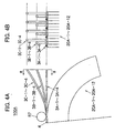
- FIG. 4A is a front view and FIG. 4B is a sectional view taken along line B-B of FIG. 4A , showing the irradiation field limiting device 100A according to the second embodiment of the present invention.
- the irradiation field limiting device 100A includes a plurality of thin aperture leaves 20A-1 to 20A-12 (about 3 to 5 mm) arranged in the thickness direction, flexible linear members 3 secured to the thick portions of the aperture leaves 20A-1 to 20A-12, a plurality of driver units 10A to 10C which drive the linear members 3 in specific amounts, and the like.
- a plurality of sliders 15 are contained in the driver unit 10A, in which the driver sections which respectively drive the linear members 3A-1 to 3A-4 are provided. Likewise, the driver sections which respectively drive the linear members 3B-1 to 3B-4 and 3C-1 to 3C-4 are provided in the driver units 10B and 10C.
- the linear members 3A-1 to 3A-4 are almost identical in axial direction.
- the linear members 3B-1 to 3B-4 and the linear members 3C-1 to 3C-4 are almost identical in axial direction, respectively.
- the linear members 3A-1 to 3A-4, the linear members 3B-1 to 3B-4, and the linear members 3C-1 to 3C-4 differ in axial direction.
- the linear members 3A-1 to 3A-4 are connected with the driver unit 10A on one end, and are respectively connected with the aperture leaves 20A-1, 20A-4, 20A-7, and 20A-10 on the other end.
- the linear members 3B-1 to 3B-4 are connected with the driver unit 10B on one end, and are respectively connected with the aperture leaves 20A-2, 20A-5, 20A-8, and 20A-11 on the other end.
- the linear members 3C-1 to 3C-4 are connected with the driver unit 10C on one end, and are respectively connected with the aperture leaves 20A-3, 20A-6, 20A-9, and 20A-12 on the other end.
- the linear members 3A-1 and 3B-1 respectively secured to the aperture leaves (e.g., aperture leaves 20A-1 and 20A-2) adjacent in the thickness direction differ in axial direction. Therefore, since the irradiation field limiting device 100A can drive the aperture leaves adjacent in the thickness direction using different driver sections, a plurality of sliders 15 can be provided in the driver sections 10A to 10C of which the size is increased to a certain extent.
- the linear members 3 connected with the sliders 15 are connected with the aperture leaves every three aperture leaves.
- the irradiation field limiting device 100A allows the driver units 10A to 10C to be disposed at specific intervals, as described above, even if the thicknesses of the aperture leaves 20A-1 to 20A-12 are reduced, the aperture leaves adjacent in the thickness direction can be driven using the driver sections with durability.
- the irradiation field limiting device 100A allows the driver units 10A to 10C to be disposed at specific intervals in units of the axial directions of the linear members 3A-1 to 3A-4, 3B-1 to 3B-4, and 3C-1 to 3C-4. Moreover, since one driver unit (e.g. driver unit 10A) need not drive the aperture leaves (e.g., aperture leaves 20A-1 and 20A-2) adjacent in the thickness direction, the size of the driver units 10A to 10C can be increased to a certain extent. This reduces cost and maintains the durability of the driver units 10A to 10C.
- the linear members 3 (3A-1 to 3A-4, 3B-1 to 3B-4, and 3C-1 to 3C-4) respectively secured to the aperture leaves 20A (aperture leaves 20A-1, 20A-4, 20A-7, and 20A-10, aperture leaves 20A-2, 20A-5, 20A-8, and 20A-11, and aperture leaves 20A-3, 20A-6, 20A-9, and 20A-12) adjacent in the thickness direction differ in axial direction, and the axial directions are set to be identical in units of a specific number (three in this embodiment) of linear members.
- the driver units 10A, 10B, and 10C contain the driver sections which respectively drive the linear members of which the axial directions are set to be identical in units of a specific number of linear members. This allows the irradiation field limiting device 100 to simply contain the driver sections by disposing the driver sections in units of the axial directions of the linear members 3 and providing the driver units 10A, 10B, and 10C containing the driver sections in units of the axial directions of the linear members 3.
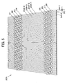
- FIG. 5 is a view showing an aperture leaf 20A according to a third embodiment of the present invention (corresponding to the cross-sectional view along the line D-D in FIG. 1 showing the first embodiment).
- the aperture leaf 20A includes aperture leaves which are arranged in the thickness direction so that the aperture leaves can freely move through rolling elements.
- the aperture leaves 20A-1 to 20A-4 are described below. As shown in FIG. 5 , when the shape of the aperture leaves 20A-1 to 20A-4 is considered as one pattern, the aperture leaf 20A is formed by repeatedly arranging the aperture leaves 20A-1 to 20A-4 in the thickness direction (described later).
- the aperture leaves 20A-1 to 20A-4 are arranged in the thickness direction so that the aperture leaves 20A-1 to 20A-4 can freely move through rolling elements 21 to 28. As shown in FIG. 5 , the side surfaces of the aperture leaves 20A-1 to 20A-4 protrude in the thickness direction to form holding portions which hold the rolling elements 21 to 28. Therefore, even when the aperture leaves 20A-1 to 20A-4 are driven and an opening occurs between the aperture leaves, strong radiation can be prevented from passing through the space between the aperture leaves 20A-1 to 20A-4. Specifically, the holding portions hold the rolling elements 21 to 28 and function as shielding portions which shield radiation.
- the strength of the aperture leaves 20A-1 to 20A-4 can be maintained at a value equal to or higher than a specific value by adjusting the thicknesses of the aperture leaves 20A-1 to 20A-4 forming the holding portions and the size of the rolling elements 21 to 28 to values equal to or higher than specific values.
- the rolling elements 21 to 28 may have an appropriate shape (e.g., ball shape, cylindrical, or conical trapezoidal) insofar as the rolling elements 21 to 28 function as bearings when the aperture leaves 20A-1 to 20A-4 are respectively driven using the linear members 3A-1, 3B-1, 3C-1, and 3A-2.
- an appropriate shape e.g., ball shape, cylindrical, or conical trapezoidal
- the rolling elements 21 to 24 are disposed at a position closer to the radiation source 1 than the rolling elements 25 to 28, and have a diameter smaller than that of the rolling elements 25 to 28.
- the aperture leaves 20A-1 to 20A-4 are smoothly driven using the linear members 3A-1, 3B-1, 3C-1, and 3A-2.
- the rolling element 23 is disposed at a position close to the radiation source 1, and the rolling element 24 is disposed at a position away from the radiation source 1.
- the rolling element 27 is disposed at a position close to the radiation source 1, and the rolling element 28 is disposed at a position away from the radiation source 1.
- the thickness of the entire aperture leaf 20A does not change depending on the size of the rolling elements 21 to 28.
- a rolling element having a diameter almost equal to the thickness of the aperture leaf 20A-1 may be held using the holding portion. Since the opening between the aperture leaves 20A-1 and 20A-2 is uniformly maintained by the rolling elements 23 and 27, a situation can be prevented in which the frictional resistance increases due to contact between the aperture leaves 20A-1 and 20A-2, whereby a large amount of load is applied to the linear member 3, the driver section 10, and the like.
- the holding portions are formed of a straight line and/or a curve formed by bending or cutting the aperture leaves 20A-1 to 20A-4. As a result, the holding portions can be formed even if the thicknesses of the aperture leaves 20A-1 to 20A-4 are reduced.
- the holding portions are disposed at different positions with respect to the irradiation direction (see FIG. 1 ).
- the holding portions are repeatedly disposed at an identical position in units of a specific number (four in this embodiment) of aperture leaves 20A-1 to 20A-4. Therefore, the aperture leaf 20A allows the holding portions to be formed by repeatedly arranging the aperture leaves of the same shape in units of a specific number. As a result, the number of types of bending or cutting can be set at a specific value when forming the aperture leaf 20A, whereby the aperture leaf 20A can be quickly formed at reduced cost.
- FIG. 6A to 6C are view showing a driver section 10-1 according to a fourth embodiment of the present invention. Note that description of the functions and the like of the same members as those of the above-described driver section 10 is appropriately omitted.
- the driver section 10-1 differs from the driver section 10 in that the driver section 10-1 includes a slider 15-1, a guide 31, an elastic member 32 (coil spring in FIG. 6A or 6B ), and the like which are provided in the base 11, for example.
- the slider 15-1 can move in the axial direction of the drive shaft 14 accompanying the rotation of the drive shaft 14, and includes a pedestal portion 15-1a and an engagement portion 15-lb connected with the pedestal section 15-1a.
- the pedestal section 15-1a includes a female thread portion 15A which engages the male thread portion 14A of the drive shaft 14, a support hole 15B through which the support shaft 16 passes, and a joint portion 15C connected with the linear member 3.
- the guide 31 is supported on the support shaft 16, can move in the axial direction of the support shaft 16, and maintains the shape of the linear member 3.
- the elastic member 32 supported on the support shaft 16 is disposed between the guides 31.
- FIG. 6A illustrates a state in which the linear member 3 is pulled into the base 11 by the slider 15-1 (i.e. a state in which the aperture leaf 20A is pulled out in the direction in which the irradiation field A is enlarged).
- the linear member 3 since the linear member 3 can freely move in the base 11 in the driver section 10 (see FIG. 1 ), the linear member 3 may buckle when the slider 15 pushes the linear member 3 out of the base 11.
- the driver section 10-1 includes the guides 31 supported on the support shaft 16 and the elastic member 32 disposed between the guides 31.
- the elastic member 32 can maintain the interval between the guides 31 approximately identical, even if the guides 31 have moved in the axial direction of the support shaft 16.
- the interval between the guides 31 is determined by the length of the elastic member 32.
- an appropriate elastic member other than the coil spring may be used insofar as the interval between the guides 31 can be maintained approximately identical.
- FIG. 6B illustrates a state in which the linear member 3 is pushed out from the base 11 by the slider 15-1 (i.e. a state in which the aperture leaf 20A is pushed in the direction in which the irradiation field A is reduced).
- the linear member 3 since only a small portion of the linear member 3 freely moves in the base 11 and the elastic member 32 provided between the guides 31 shrinks, the interval between the guides 31 is reduced, whereby the linear member 3 can be reliably prevented from buckling.
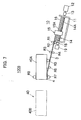
- FIG. 7 is a view showing an irradiation field limiting device 100B according to a fifth embodiment of the present invention.
- the irradiation field limiting device 100B differs from the irradiation field limiting device 100 according to the first embodiment in that one end of the linear member 3 is secured to an approximately rectangular aperture leaf 40 (aperture leaf 40A in FIG. 7 ) through the connection section 4 tangentially to the shape on the outer circumference of the aperture leaf 40.
- the other end of the linear member 3 is connected with the slider 15 provided in the driver section 10.
- the approximately rectangular aperture leaf 40A is driven a specific amount along a path guided by the rollers R5, R7, and R8 along with the movement of the slider 15.
- the aperture leaf 40A can be accurately driven along the path by securing the flexible linear member 3 to the aperture leaf 40A.
Landscapes
- Physics & Mathematics (AREA)
- Spectroscopy & Molecular Physics (AREA)
- Engineering & Computer Science (AREA)
- General Engineering & Computer Science (AREA)
- High Energy & Nuclear Physics (AREA)
- Radiation-Therapy Devices (AREA)
- Apparatus For Radiation Diagnosis (AREA)
Abstract
Claims (22)
- Un dispositif de limitation pour un champ de rayonnement (100) protégeant contre le rayonnement d'une source de rayonnement (1) en entraînant une multitude de pales d'ouverture (20; 40), en quantité spécifique pour limiter un champ de rayonnement dans un cadre désiré, le dispositif de limitation pour un champ de rayonnement (100) comprenant:une multitude de pales d'ouverture (20; 40) comprenant une surface circonférentielle,une section d'entraînement (10; 10-1),un membre linéaire flexible (3), don't une extrémité est fixée à une pale d'ouverture (20; 40), l'autre extrémité du membre linéaire flexible (3) étant connectée à la section d'entraînement (10; 10-1) qui entraîne le membre linéaire (3) dans une direction axiale pour produire un mouvement de la pale d'ouverture (20; 40),caractérisé par les pales d'ouverture (20; 40) étant arrangées dans une direction d'épaisseur côte à côte, une extrémité du membre linéaire flexible (3) étant fixée à une surface circonférentielle interne ou externe de la pale d'ouverture (20; 40), et la section d'entraînement (10; 10-1) entraînant le membre linéaire flexible (3) tout en augementant ou réduisant une partie de contact entre le membre linéaire flexible (3) et la surface circonférentielle interne ou externe de la pale d'ouverture (20; 40) en cambrant le membre linéaire flexible (3).
- Le dispositif de limitation pour un champ de rayonnement selon la revendication 1, la section d'entraînement comprenant:une base;un arbre d'entraînement connecté à une source d'entraînement par une partie de connection et inséré dans la base; etun poussoir qui bouge le long d'une direction axiale de l'arbre d'entraînement accompagnant la rotation de l'arbre d'entraînement et qui est connecté au membre linéaire.
- Le dispositif de limitation pour un champ de rayonnement selon la revendication 2,
la partie de connection comprenant une section de limitation du couple qui limite la transmission du couple à un couple spécifique ou une valeur supérieure. - Le dispositif de limitation pour un champ de rayonnement selon la revendication 3,
la partie de connection comprenant un mécanisme d'accouplement qui transmet une force d'entraînement à l'arbre d'entraînement ou qui déconnecte la force d'entraînement de l'arbre d'entraînement; et
le dispositif de limitation pour un champ de rayonnement comprenant une section de contrôle qui empêche la force d'entraînement d'être transmise à l'arbre d'entraînement en utilisant le mécanisme d'accouplement quand la section de limitation du couple a été en opération pendant un certain temps. - Le dispositif de limitation pour un champ de rayonnement selon la revendication 2,
la partie de connection comprenant un mécanisme d'accouplement qui transmet une force d'entraînement à l'arbre d'entraînement ou qui déconnecte la force d'entraînement de l'arbre d'entraînement; et
le dispositif de limitation pour un champ de rayonnement comprenant: une section de détection de position qui détecte une position de la pale d'ouverture; et une section de contrôle empêchant la transmission de la force d'entraînement à l'arbre d'entraînement en utilisant le mécanisme d'accouplement pour arrêter le mouvement de la pale d'ouverture quand la section de détection de position a détecté le mouvement de la pale d'ouverture vers une position cible. - Le dispositif de limitation pour un champ de rayonnement selon la revendication 2, comprenant
une section de transmission de la force d'entraînement qui transmet une force d'entraînement de la source d'entraînement à une multitude d'arbres d'entraînement;
une multitude de mécanismes d'accouplement qui transmettent la force d'entraînement aux arbres d'entraînement ou déconnectent la force d'entraînement des arbres d'entraînement; et
une section de contrôle qui peut entraîner chacune des pales d'ouverture en transmettant la force d'entraînement de la source d'entraînement dans des unités des arbres d'entraînement en contrôlant chacun des mécanismes d'accouplement. - Le dispositif de limitation pour un champ de rayonnement selon la revendication 2,
avec un poussoir ayant une section de filet femelle; et
l'arbre d'entraînement ayant une section de filet mâle qui intervient dans la section de filet femelle et déplace le poussoir en tournant dans la direction axiale de l'arbre d'entraînement. - Le dispositif de limitation pour un champ de rayonnement selon la revendication 1,
la pale d'ouverture étant en forme d'éventail ou à peu près rectangulaire. - Le dispositif de limitation pour un champ de rayonnement selon la revendication 1,
l'élément linéaire étant un fil métallique continu, un câble formé en tordant les fils métalliques, ou un tube creux. - Le dispositif de limitation pour un champ de rayonnement selon la revendication 2, comprenant:un manche de support prévu dans la base et arrangé approximativement en parallèle à l'arbre d'entraînement à une distance spécifique par rapport à l'arbre d'entraînement;au moins un guidage supporté au manche de support de sorte que le guidage peut se déplacer dans une direction axiale du manche de support et maintient une forme du membre linéaire; etun membre élastique qui est disposé entre les guidages et qui maintient une distance à peu près identique entre les guidages.
- Le dispositif de limitation pour un champ de rayonnement selon la revendication 2, comprenant:un capteur de position absolue qui mesure une position absolue d'au moins une des pales d'ouverture et du poussoir;etun capteur de haute-résolution de position relative qui mesure le degré de déplacement par rapport à une position spécifique d'au moins une des pales d'ouverture et du poussoir, mesuré en utilisant le capteur de position absolue.
- Le dispositif de limitation pour un champ de rayonnement selon la revendication 1,
les pales d'ouverture étant arrangées dans la direction de l'épaisseur de sorte que les pales d'ouverture puissent se déplacer librement grâce à des éléments roulants; et
une surface latérale de la pale d'ouverture s'étendant dans la direction de l'épaisseur pour former une partie de soutien qui soutient l'élément roulant. - Le dispositif de limitation pour un champ de rayonnement selon la revendication 12,
la partie de soutien suivant ou une ligne droite ou une courbe pour soutenir l'élément roulant. - Le dispositif de limitation pour un champ de rayonnement selon la revendication 12,
un des éléments roulants avoisinants qui sont prévus de part et d'autre de la pale d'ouverture étant disposé dans une position près de la source de rayonnement et l'autre élément étant disposé dans une position éloignée de la source de rayonnement. - Le dispositif de limitation pour un champ de rayonnement selon la revendication 12,
les parties de soutien étant disposées dans des positions différentes par rapport à la direction de rayonnement et étant disposées dans une position identique dans des unités d'un nombre spécifique de pales d'ouverture. - Le dispositif de limitation pour un champ de rayonnement selon la revendication 12,
la partie de soutien étant une partie de protection pour éviter que le rayonnement ne s'échappe par une espace entre les pales d'ouverture avoisinantes. - Le dispositif de limitation pour un champ de rayonnement selon la revendication 1, comprenant une partie de protection protégeant contre le rayonnement dans une ouverture entre les pales d'ouverture avoisinantes.
- Le dispositif de limitation pour un champ de rayonnement selon la revendication 1,
les membres linéaires respectivement fixés aux pales d'ouverture avoisinantes dans la direction de l'épaisseur étant différents par rapport à leur direction axiale. - Le dispositif de limitation pour un champ de rayonnement selon la revendication 18,
la section d'entraînement entraînant la pale d'ouverture dont la direction axiale du membre linéaire est choisie d'être identique dans des unités d'un nombre spécifique de membres linéaires. - Le dispositif de limitation pour un champ de rayonnement selon la revendication 1,
les membres linéaires respectivement fixés aux pales d'ouverture avoisinantes dans la direction de l'épaisseur étant différents par rapport à leur direction axiale et identiques dans des unités d'un nombre spécifique de membres linéaires; et le dispositif de limitation pour un champ de rayonnement comprenant une multitude d'unités d'entraînement, chacune d'elles comprenant une multitude de sections d'entraînement entraînant les membres linéaires dont les directions axiales sont choisis d'être identique dans des unités d'un nombre spécifique de membres linéaires. - Le dispositif de limitation pour un champ de rayonnement selon la revendication 1, comprenant:une partie de soutien des membre linéaire soutenant le membre linéaire entre la pale d'ouverture et la section d'entraînement de sorte que le membre linéaire peut se déplacer dans la direction axiale pour éviter que le membre linéaire bombe.
- Le dispositif de limitation pour un champ de rayonnement selon la revendication 1,
le membre linéaire entraînant la pale d'ouverture tout en contactant la partie épaisse et étant passagèrement courbé dans une direction opposée de la partie de contact entre le membre linéaire et la partie épaisse et poussant la partie en contact avec la partie épaisse pour éviter que le membre linéaire bombe.
Applications Claiming Priority (2)
| Application Number | Priority Date | Filing Date | Title |
|---|---|---|---|
| JP2004005922 | 2004-01-13 | ||
| PCT/JP2005/000294 WO2005068019A1 (fr) | 2004-01-13 | 2005-01-13 | Dispositif permettant de limiter un champ dans lequel un rayonnement est emis |
Publications (3)
| Publication Number | Publication Date |
|---|---|
| EP1712254A1 EP1712254A1 (fr) | 2006-10-18 |
| EP1712254A4 EP1712254A4 (fr) | 2007-07-18 |
| EP1712254B1 true EP1712254B1 (fr) | 2009-05-20 |
Family
ID=34792119
Family Applications (1)
| Application Number | Title | Priority Date | Filing Date |
|---|---|---|---|
| EP05703533A Expired - Lifetime EP1712254B1 (fr) | 2004-01-13 | 2005-01-13 | Dispositif permettant de limiter un champ dans lequel un rayonnement est emis |
Country Status (5)
| Country | Link |
|---|---|
| US (1) | US7965819B2 (fr) |
| EP (1) | EP1712254B1 (fr) |
| JP (1) | JP4642660B2 (fr) |
| DE (1) | DE602005014539D1 (fr) |
| WO (1) | WO2005068019A1 (fr) |
Families Citing this family (24)
| Publication number | Priority date | Publication date | Assignee | Title |
|---|---|---|---|---|
| DE102006039793B3 (de) | 2006-08-24 | 2008-01-24 | Siemens Ag | Lamellenkollimator und Strahlentherapiegerät |
| JP2008229324A (ja) | 2007-02-23 | 2008-10-02 | Toshiba Corp | 放射線治療装置 |
| US8017915B2 (en) | 2008-03-14 | 2011-09-13 | Reflexion Medical, Inc. | Method and apparatus for emission guided radiation therapy |
| US8938051B2 (en) * | 2008-04-21 | 2015-01-20 | Elekta Ab (Publ) | Multi-leaf collimators |
| JP5027067B2 (ja) * | 2008-06-27 | 2012-09-19 | 三菱電機株式会社 | 粒子線治療装置用マルチリーフコリメータ |
| JP2011136038A (ja) * | 2009-12-28 | 2011-07-14 | Right Manufacturing Co Ltd | 放射線照射野限定装置及び線状部材駆動装置 |
| CN106563211B (zh) | 2011-03-31 | 2019-10-18 | 反射医疗公司 | 用于在发射引导的放射治疗中使用的系统和方法 |
| FI125341B (en) * | 2012-07-09 | 2015-08-31 | Beneq Oy | Apparatus and method for treating substrate |
| US10367403B2 (en) * | 2014-08-21 | 2019-07-30 | General Electric Company | Systems and methods for independent motion of parallel actuators |
| US10500416B2 (en) | 2015-06-10 | 2019-12-10 | Reflexion Medical, Inc. | High bandwidth binary multi-leaf collimator design |
| WO2017041750A1 (fr) | 2015-09-10 | 2017-03-16 | Shanghai United Imaging Healthcare Co., Ltd. | Collimateur à lames multiples et système d'entrainement |
| EP3426345B1 (fr) | 2016-03-09 | 2021-06-23 | RefleXion Medical, Inc. | Procédés de génération de carte de fluence pour radiothérapie |
| CN110234275B (zh) | 2016-11-15 | 2023-08-22 | 反射医疗公司 | 用于发射引导式高能光子传输的系统 |
| CN116943051A (zh) | 2016-11-15 | 2023-10-27 | 反射医疗公司 | 放射治疗患者平台 |
| WO2018093849A1 (fr) | 2016-11-15 | 2018-05-24 | Reflexion Medical, Inc. | Procédés destinés à l'administration d'un rayonnement en radiothérapie guidée par émission |
| WO2018183748A1 (fr) | 2017-03-30 | 2018-10-04 | Reflexion Medical, Inc. | Systèmes et procédés de radiothérapie avec suivi de tumeur |
| WO2019014387A1 (fr) | 2017-07-11 | 2019-01-17 | Reflexion Medical, Inc. | Procédés de gestion de rémanence pour détecteur tep |
| WO2019032911A1 (fr) | 2017-08-09 | 2019-02-14 | Reflexion Medical, Inc. | Systèmes et procédés de détection de défaut dans une radiothérapie guidée par émission |
| US11369806B2 (en) | 2017-11-14 | 2022-06-28 | Reflexion Medical, Inc. | Systems and methods for patient monitoring for radiotherapy |
| CN107769483B (zh) * | 2017-11-22 | 2019-09-27 | 清华大学 | 一种直线电机的双传感反馈和传动系统 |
| CN109173080B (zh) | 2018-07-23 | 2021-03-23 | 上海联影医疗科技股份有限公司 | 一种混合驱动光栅叶片的装置和方法 |
| US10892064B2 (en) | 2018-12-05 | 2021-01-12 | Shanghai United Imaging Healthcare Co., Ltd. | Multi-leaf collimator |
| JP7482693B2 (ja) * | 2020-06-09 | 2024-05-14 | 富士フイルムヘルスケア株式会社 | X線画像診断装置、および、その運転方法 |
| KR102752687B1 (ko) * | 2023-06-30 | 2025-01-10 | 오스템임플란트 주식회사 | 엑스선 촬영장치 |
Family Cites Families (17)
| Publication number | Priority date | Publication date | Assignee | Title |
|---|---|---|---|---|
| JPS59191869A (ja) | 1983-04-15 | 1984-10-31 | 株式会社日立製作所 | 冷蔵庫のダンパ−装置 |
| JPS59191869U (ja) * | 1983-06-06 | 1984-12-19 | 日産自動車株式会社 | 駆動源ユニツト |
| JPS62136338A (ja) * | 1985-12-03 | 1987-06-19 | Daihatsu Motor Co Ltd | スピンドルヘツドのトルクリミツタ |
| JPH03143455A (ja) * | 1989-10-31 | 1991-06-19 | Toshiba Corp | 多分割型絞り装置 |
| JPH0710282B2 (ja) * | 1990-03-20 | 1995-02-08 | 三菱電機株式会社 | 放射線照射野限定装置 |
| JPH06300896A (ja) | 1993-04-13 | 1994-10-28 | Hitachi Medical Corp | 放射線治療装置の多分割絞り装置における絞り駆動機構 |
| JP2529523B2 (ja) | 1993-06-23 | 1996-08-28 | メカテック株式会社 | 移載装置 |
| JPH07204284A (ja) * | 1994-01-11 | 1995-08-08 | Hitachi Medical Corp | 放射線治療装置の多分割絞り駆動機構 |
| DE19536804A1 (de) | 1995-10-02 | 1997-04-03 | Deutsches Krebsforsch | Konturenkollimator für die Strahlentherapie |
| JPH09131411A (ja) | 1995-11-09 | 1997-05-20 | Mitsubishi Electric Corp | X線照射用ツーブス |
| FR2818428A1 (fr) | 2000-12-19 | 2002-06-21 | Ge Med Sys Global Tech Co Llc | Collimateur ajustable |
| JP2002186677A (ja) * | 2000-12-22 | 2002-07-02 | Toshiba Corp | 放射線治療装置及びマイクロマルチリーフコリメータ |
| JP2002210026A (ja) | 2001-01-19 | 2002-07-30 | Toshiba Corp | 放射線治療装置と放射線の照射野設定用絞り装置 |
| JP3894733B2 (ja) | 2001-02-15 | 2007-03-22 | 本田技研工業株式会社 | 電動駐車ブレーキ装置 |
| JP2003093524A (ja) | 2001-09-25 | 2003-04-02 | Mitsubishi Electric Corp | 放射線治療システム |
| JP2004089214A (ja) | 2002-08-29 | 2004-03-25 | Natl Inst Of Radiological Sciences | 空気シリンダー駆動マルチリーフコリメータ |
| JP4184839B2 (ja) | 2003-03-13 | 2008-11-19 | 株式会社東芝 | 多分割絞り装置 |
-
2005
- 2005-01-13 EP EP05703533A patent/EP1712254B1/fr not_active Expired - Lifetime
- 2005-01-13 DE DE602005014539T patent/DE602005014539D1/de not_active Expired - Lifetime
- 2005-01-13 JP JP2005517053A patent/JP4642660B2/ja not_active Expired - Fee Related
- 2005-01-13 WO PCT/JP2005/000294 patent/WO2005068019A1/fr not_active Ceased
- 2005-01-13 US US10/585,919 patent/US7965819B2/en not_active Expired - Fee Related
Also Published As
| Publication number | Publication date |
|---|---|
| JPWO2005068019A1 (ja) | 2008-04-24 |
| DE602005014539D1 (de) | 2009-07-02 |
| US7965819B2 (en) | 2011-06-21 |
| WO2005068019A1 (fr) | 2005-07-28 |
| JP4642660B2 (ja) | 2011-03-02 |
| EP1712254A1 (fr) | 2006-10-18 |
| US20080292058A1 (en) | 2008-11-27 |
| EP1712254A4 (fr) | 2007-07-18 |
Similar Documents
| Publication | Publication Date | Title |
|---|---|---|
| EP1712254B1 (fr) | Dispositif permettant de limiter un champ dans lequel un rayonnement est emis | |
| EP2021729B1 (fr) | Ensemble capteur de vitesse de moteur | |
| JP4911905B2 (ja) | 回転対称精密部品を測定する装置、cnc測定装置及び方法 | |
| US8513910B2 (en) | Method of returning pointer to origin point | |
| JP6505468B2 (ja) | ノギスのジョウを移動させるためのローラ機構及びノギスに測定力を印加する方法 | |
| JP2017524115A (ja) | センサユニットを備えるクラッチアッセンブリ及び当該クラッチアッセンブリを備える駆動アッセンブリ | |
| CN107132239B (zh) | 一种医疗设备的准直系统及运动单元位置精度监测方法 | |
| EP2893292B1 (fr) | Actionnement de bras d'extensomètre à distance | |
| US20150069107A1 (en) | Method For Controlling Feeding Length Of Wire And Displacement Sensing System For The Same | |
| EP3402616B1 (fr) | Presse à dresser et procédé de dressage de faux-ronds ou de défauts de rectitude sur des pièces de forme allongée comportant au moins une zone spiralée, comme une vis sans fin transporteuse, notamment une vis sans fin d'extrudeuse | |
| WO2019141489A1 (fr) | Unité à rotor péristaltique, pince et raccord de tube | |
| US5808250A (en) | Mobile member position detection apparatus | |
| US5121558A (en) | Method and apparatus for controlling and indicating angular rotation of a shaft | |
| EP1058105B1 (fr) | Mesure de jeu de rouages avec une butée | |
| EP0181415A1 (fr) | Dispositif de positionnement pour vérin sans tige | |
| US20220152293A1 (en) | Drive device and medical infusion pump | |
| CN210668101U (zh) | 套管输送检测机构及变压器线圈穿管绕线机 | |
| CN208916404U (zh) | 管线输送系统 | |
| EP2340871A2 (fr) | Appareil de limitation de champ d'irradiation et dispositif de commande d'élément linéaire | |
| EP2740406A1 (fr) | Machine de photographie aux rayons X | |
| EP0479758B1 (fr) | Système encapsulé pour mesurer la longueur | |
| EP2781933B1 (fr) | Capteur optique | |
| CN110853917A (zh) | 套管输送检测机构及变压器线圈穿管绕线机 | |
| DE102021122242A1 (de) | Vorrichtung und Verfahren zur Bestimmung wenigstens einer Messgröße in einem Riemen-betriebenen Variatorgetriebe, Regelungssystem, Computerprogramm und Riemen | |
| EP4566736A1 (fr) | Machine de cintrage à diamètres précis |
Legal Events
| Date | Code | Title | Description |
|---|---|---|---|
| PUAI | Public reference made under article 153(3) epc to a published international application that has entered the european phase |
Free format text: ORIGINAL CODE: 0009012 |
|
| 17P | Request for examination filed |
Effective date: 20060810 |
|
| AK | Designated contracting states |
Kind code of ref document: A1 Designated state(s): DE NL SE |
|
| DAX | Request for extension of the european patent (deleted) | ||
| RBV | Designated contracting states (corrected) |
Designated state(s): DE NL SE |
|
| A4 | Supplementary search report drawn up and despatched |
Effective date: 20070615 |
|
| RIC1 | Information provided on ipc code assigned before grant |
Ipc: A61N 5/10 20060101AFI20050802BHEP Ipc: G21K 5/00 20060101ALI20070611BHEP Ipc: G21K 1/02 20060101ALI20070611BHEP Ipc: G21K 1/04 20060101ALI20070611BHEP |
|
| 17Q | First examination report despatched |
Effective date: 20071121 |
|
| GRAP | Despatch of communication of intention to grant a patent |
Free format text: ORIGINAL CODE: EPIDOSNIGR1 |
|
| GRAS | Grant fee paid |
Free format text: ORIGINAL CODE: EPIDOSNIGR3 |
|
| GRAA | (expected) grant |
Free format text: ORIGINAL CODE: 0009210 |
|
| AK | Designated contracting states |
Kind code of ref document: B1 Designated state(s): DE NL SE |
|
| REF | Corresponds to: |
Ref document number: 602005014539 Country of ref document: DE Date of ref document: 20090702 Kind code of ref document: P |
|
| PG25 | Lapsed in a contracting state [announced via postgrant information from national office to epo] |
Ref country code: SE Free format text: LAPSE BECAUSE OF FAILURE TO SUBMIT A TRANSLATION OF THE DESCRIPTION OR TO PAY THE FEE WITHIN THE PRESCRIBED TIME-LIMIT Effective date: 20090820 |
|
| PLBE | No opposition filed within time limit |
Free format text: ORIGINAL CODE: 0009261 |
|
| STAA | Information on the status of an ep patent application or granted ep patent |
Free format text: STATUS: NO OPPOSITION FILED WITHIN TIME LIMIT |
|
| 26N | No opposition filed |
Effective date: 20100223 |
|
| PGFP | Annual fee paid to national office [announced via postgrant information from national office to epo] |
Ref country code: DE Payment date: 20111031 Year of fee payment: 8 |
|
| PGFP | Annual fee paid to national office [announced via postgrant information from national office to epo] |
Ref country code: NL Payment date: 20120125 Year of fee payment: 8 |
|
| REG | Reference to a national code |
Ref country code: NL Ref legal event code: V1 Effective date: 20130801 |
|
| PG25 | Lapsed in a contracting state [announced via postgrant information from national office to epo] |
Ref country code: DE Free format text: LAPSE BECAUSE OF NON-PAYMENT OF DUE FEES Effective date: 20130801 Ref country code: NL Free format text: LAPSE BECAUSE OF NON-PAYMENT OF DUE FEES Effective date: 20130801 |
|
| REG | Reference to a national code |
Ref country code: DE Ref legal event code: R119 Ref document number: 602005014539 Country of ref document: DE Effective date: 20130801 |