EP1712362A2 - Procédé pour changer automatiquement un changeur de bobines lors d'un changement de production d'une machine rotative d'impression - Google Patents
Procédé pour changer automatiquement un changeur de bobines lors d'un changement de production d'une machine rotative d'impression Download PDFInfo
- Publication number
- EP1712362A2 EP1712362A2 EP06100916A EP06100916A EP1712362A2 EP 1712362 A2 EP1712362 A2 EP 1712362A2 EP 06100916 A EP06100916 A EP 06100916A EP 06100916 A EP06100916 A EP 06100916A EP 1712362 A2 EP1712362 A2 EP 1712362A2
- Authority
- EP
- European Patent Office
- Prior art keywords
- roll
- new
- last
- remaining
- web
- Prior art date
- Legal status (The legal status is an assumption and is not a legal conclusion. Google has not performed a legal analysis and makes no representation as to the accuracy of the status listed.)
- Granted
Links
Images




Classifications
-
- B—PERFORMING OPERATIONS; TRANSPORTING
- B65—CONVEYING; PACKING; STORING; HANDLING THIN OR FILAMENTARY MATERIAL
- B65H—HANDLING THIN OR FILAMENTARY MATERIAL, e.g. SHEETS, WEBS, CABLES
- B65H19/00—Changing the web roll
- B65H19/10—Changing the web roll in unwinding mechanisms or in connection with unwinding operations
- B65H19/18—Attaching, e.g. pasting, the replacement web to the expiring web
- B65H19/1857—Support arrangement of web rolls
- B65H19/1868—The roll support being of the turret type
-
- B—PERFORMING OPERATIONS; TRANSPORTING
- B65—CONVEYING; PACKING; STORING; HANDLING THIN OR FILAMENTARY MATERIAL
- B65H—HANDLING THIN OR FILAMENTARY MATERIAL, e.g. SHEETS, WEBS, CABLES
- B65H19/00—Changing the web roll
- B65H19/10—Changing the web roll in unwinding mechanisms or in connection with unwinding operations
- B65H19/18—Attaching, e.g. pasting, the replacement web to the expiring web
- B65H19/1805—Flying splicing, i.e. the expiring web moving during splicing contact
- B65H19/1826—Flying splicing, i.e. the expiring web moving during splicing contact taking place at a distance from the replacement roll
- B65H19/1836—Flying splicing, i.e. the expiring web moving during splicing contact taking place at a distance from the replacement roll the replacement web being accelerated or running prior to splicing contact
-
- B—PERFORMING OPERATIONS; TRANSPORTING
- B65—CONVEYING; PACKING; STORING; HANDLING THIN OR FILAMENTARY MATERIAL
- B65H—HANDLING THIN OR FILAMENTARY MATERIAL, e.g. SHEETS, WEBS, CABLES
- B65H19/00—Changing the web roll
- B65H19/10—Changing the web roll in unwinding mechanisms or in connection with unwinding operations
- B65H19/18—Attaching, e.g. pasting, the replacement web to the expiring web
- B65H19/1842—Attaching, e.g. pasting, the replacement web to the expiring web standing splicing, i.e. the expiring web being stationary during splicing contact
- B65H19/1852—Attaching, e.g. pasting, the replacement web to the expiring web standing splicing, i.e. the expiring web being stationary during splicing contact taking place at a distance from the replacement roll
-
- B—PERFORMING OPERATIONS; TRANSPORTING
- B65—CONVEYING; PACKING; STORING; HANDLING THIN OR FILAMENTARY MATERIAL
- B65H—HANDLING THIN OR FILAMENTARY MATERIAL, e.g. SHEETS, WEBS, CABLES
- B65H2301/00—Handling processes for sheets or webs
- B65H2301/40—Type of handling process
- B65H2301/41—Winding, unwinding
- B65H2301/417—Handling or changing web rolls
- B65H2301/41702—Handling or changing web rolls management and organisation of stock and production
-
- B—PERFORMING OPERATIONS; TRANSPORTING
- B65—CONVEYING; PACKING; STORING; HANDLING THIN OR FILAMENTARY MATERIAL
- B65H—HANDLING THIN OR FILAMENTARY MATERIAL, e.g. SHEETS, WEBS, CABLES
- B65H2511/00—Dimensions; Position; Numbers; Identification; Occurrences
- B65H2511/10—Size; Dimensions
- B65H2511/12—Width
-
- B—PERFORMING OPERATIONS; TRANSPORTING
- B65—CONVEYING; PACKING; STORING; HANDLING THIN OR FILAMENTARY MATERIAL
- B65H—HANDLING THIN OR FILAMENTARY MATERIAL, e.g. SHEETS, WEBS, CABLES
- B65H2557/00—Means for control not provided for in groups B65H2551/00 - B65H2555/00
-
- B—PERFORMING OPERATIONS; TRANSPORTING
- B65—CONVEYING; PACKING; STORING; HANDLING THIN OR FILAMENTARY MATERIAL
- B65H—HANDLING THIN OR FILAMENTARY MATERIAL, e.g. SHEETS, WEBS, CABLES
- B65H2557/00—Means for control not provided for in groups B65H2551/00 - B65H2555/00
- B65H2557/20—Calculating means; Controlling methods
- B65H2557/23—Recording or storing data
-
- B—PERFORMING OPERATIONS; TRANSPORTING
- B65—CONVEYING; PACKING; STORING; HANDLING THIN OR FILAMENTARY MATERIAL
- B65H—HANDLING THIN OR FILAMENTARY MATERIAL, e.g. SHEETS, WEBS, CABLES
- B65H2801/00—Application field
- B65H2801/03—Image reproduction devices
- B65H2801/21—Industrial-size printers, e.g. rotary printing press
Definitions
- the invention relates to a method for fully automatic conversion of a roll changer during production changeover to a rotary printing press according to the preamble of claim 1 or 2.
- the conversion of a production order in a printing house requires u.a. a conversion of all reel splicers, which supply a rotary printing press.
- the reel changer is usually set up manually for the material rolls required in the new production order.
- a flying reel change was previously only possible within a running production order, wherein in the reelstand similar material rolls were successively provided, which were linked by appropriate bonding to a "continuous" material web.
- the DE 44 35 429 A1 describes a web-fed rotary printing press with an adjustable reel splicer for receiving printing substrate webs with different widths.
- a control device supports the production change during the production of the printing press.
- the post-published DE 102 45 658 A1 discloses methods and apparatus for automatically supplying material to a printing press.
- the US 4,967,074 describes a reel splitter where the beginning of a residual roll wound up and secured by means of an adhesive device.
- the invention has for its object to provide a method for fully automatic conversion of a roll changer in production changeover to a rotary printing press.
- the advantages achieved by the invention are, in particular, that the production with the follow-up order can be continued without great delays, which have hitherto been caused by the device of the roll changer on another roll of material.
- the unproductive set-up times for the reel changer can be virtually eliminated in this way.
- the method is characterized in particular by the fact that no operator intervention in the reel splitter in a production change is necessary and that the setting of the roll changer is performed on the new roll of material already during the expiration of the last roll of material of the expiring production, so that no time delay at startup of new production is created.
- Mainly the method is used when converting the production from a narrow to a wide roll of material or vice versa, but it is also possible to automatically convert other roll shapes with the process in the roll changer. For example, when changing over to a new grammage and / or new type of material, in particular paper type, a different web speed must be set when a material web is drawn in. For a new reel diameter, a different angle for a reel arm twist must be selected. For rolls of material provided with an adapter, other conditions must be observed when the roll of material rolls up. All of these conversion requirements can be automated using the invention.
- the method is integrated in a preferred embodiment in an automated roll logistics plant with optional access to different role positions.
- a control center of the roll logistics system ensures that all reelstands of a rotary press with material rolls are supplied.
- the data of a follow-up order are already known in the control center, such as a new roll width and / or a new roll diameter and / or a grammage and / or paper type of a new roll of material.
- This roll logistics system ensures that when the last material roll of the current production runs off, a new material roll (with possibly different properties, in particular material width) is already arranged in the roll changer for the subsequent order. Further specific parameters of the follow-up order can be integrated into the procedure if required.
- a control unit which can be integrated in the reel changer or in a control center, contains data and control programs about or for the reel changer, such as limits for roll widths to be processed, adjustment routines for the actuation of the support arms, adjustment of the web train speed and others.
- the control unit imports characteristic data of the new roll of material.
- the acquisition of the characteristic data can be detected by a barcode reader and automatically read into the controller of the reel splitter. These can be sent, for example, from the control center or be encrypted on a bar code label and / or stored as RFID.
- the label can z. B. be mounted on the sleeve.
- a required distance of the support arms is determined from the special characteristic date of the new roll width in the control unit in connection with the device data of the roll changer, and preferably set automatically via the roll data set, and a signal for adjusting the support arms triggered on the new roll width.
- Other operating parameters of the roll changer can also be varied depending on the read characteristics. If the brackets are set to the distance determined by the control system, an automatic broaching of the new roll of material takes place.
- the new roll of material is already adhesively prepared with an adhesive strip or the like.
- the return of the updated role data set can be done via a higher-level control system.
- a Rollenarmverfitung takes place in an adhesive position.
- the new roll of material is then accelerated.
- a roll change takes place in principle in the same way as a flying roll change during production.
- the material web of the running material roll is guided tightly along the new roll of material.
- a favorable speed can be determined by the control unit for this purpose.
- the remaining roll of the old, expired production order is now preferably pivoted to a position close to the gluing device.
- the material web or the web start of the remaining roll whose residual length is known, is wound and shortly before reaching the end of the remaining flag an adhesive is applied to the remaining roll, so that when winding the remaining flag this sticks to the residual role and by pressing with the adhesive roller is secured. Subsequently, the remaining roll is automatically adjusted and returned to the logistics plant.
- the characteristics of this old material roll or the remaining role are known in the reel changer. These can be sent from the control unit to the control center or attached to the rest of the roll by means of a barcode label.
- a reel changer system for supplying a rotary printing machine is shown schematically in a view from above.
- Five reelstands 01 are integrated by way of example into a reel logistics system, which further comprises suitable logistics elements, such as a transport section 02 and a transport vehicle 04.
- suitable logistics elements such as a transport section 02 and a transport vehicle 04.
- An unillustrated control station monitors and organizes the delivery of the roll changer 01 with the required material rolls 05; 06 and sends characteristic data about the material rolls 05; 06 to the respective reel splitter 01.
- the reel changers 01 are converted fully automatically to a follow-on production order. The essential steps of this conversion have already been explained above. Also from the detailed description below are those for a fully automatic production change at the roll changer 01 required process steps visible.
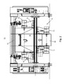
- Fig. 2 shows the roll changer 01 in front view during the conversion of production to a follow-up order.
- the follow-up order differs from the currently processed production order especially in that a wider material roll is used.
- a running, narrow roll of material 08 in support arms 10 of a first roller arm 12 of the roll changer 01.
- the collection of the material web of this roll of material 08 takes place in the direction of the illustrated straight arrow.
- the direction of rotation of the new roll of material 14 is indicated by a rotation arrow.
- an adhesive strip 20 is attached, which is used in a conventional manner for the connection of the new material web with the running material web.
- a production changeover from a wide roll of material is shown on a narrow roll of material analogous to the representation in Fig. 2.
- the expiring roll of material 08 has a greater width than the new roll of material 14 of the follow-up order.
- the adhesive strip 20 is attached on the new roll of material 14. It can be seen that between the two process steps of Figures 1 and 2, an adjustment of the support arms 10; 16 is necessary because at the two support positions material rolls 08; 14 are used with different width. Before or during the Aufachsen of the new roll of material 14 so takes place an adjustment of the support arms 16 of the second roller arm 18 to a narrower setting, while the support arms 10 of the first roller arm 12 are compared to FIG. 1 set wider.
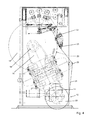
- the expiring roll of material 08 of the predecessor job is stored in the first roller arm 12 of the roll changer 01, which consists of the two, in the image plane behind one another supporting arms 10 is formed.
- the new roll of material 14 of the subsequent order is stored in the support arms 16 of the second roller arm 18.
- the second roller arm 18 is pivoted into an adhesive position.
- On the new roll of material 14, the adhesive strip 20 is attached.
- An adhesive device 22 is pivoted in the adhesive position to make the bonding of the material web of the new roll of material 14 with the running material web 24 of the roll of material 08 at the desired time with appropriate activation.
- the new roll of material 14 is accelerated in the direction of rotation arrow.
- the material web 24 of the running material roll 08 is guided past guides 26 tightly against the new material roll 14.
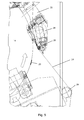
- FIG. 5 is a detail view of the roll changer 01 shown in FIG. 4.
- the material web 24 of the outgoing material roll 08 guided tightly along the new material roll 14 can be seen.
- the adhesive strip 20 approaches the gluing device 22 in the direction of rotation of the arrow an adhesive roll 28 are lowered onto the new roll of material 14.
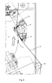
- the state with lowered adhesive roller 28 is shown in Fig. 6.
- the draining material web 24 is thereby pressed against the adhesive strip 20 of the new roll of material 14.
- the adhesive strip 20 separates from the roll of material 14 and the beginning of the roll of the new roll of material 14 is taken from the running web 24.
- the control unit can set the right time for disconnection from preset values for the desired Automatically determine the overhang of the expired web of material 08 and the process-dependent values of the web speed and the type of material used. If necessary, a higher web tension must be set by the control unit here for a short time in order to separate the material web cleanly.
- Fig. 8 shows the state after the role or production change.
- a new material web 32 is now drawn in by the new material roll 14. After the splice 34 remains a residual lug 35 on the web 32.
- the adhesive device 22 is pivoted back.
- the outgoing material roll 08 is often not completely used up. Unlike the flying roll change within a production cycle, where the outgoing roll of material 08 is largely completely used up and only a technologically related remainder of material remains on the expired roll of material 08, therefore, not only the roller sleeve can be discarded during production change. Rather, an orderly removal and re-storage of the expired roll of material 08 is required.
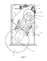
- a residual roll 36 which corresponds to the originally running material roll 08, is pivoted with the roll arm 12 into an upper position, in which the cut web start 38 of the rest roll 36 hangs freely or is guided into the intended web guides ,
- the adhesive device 22 is brought into an approach position to the remaining roll 36.
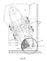
- the length of the remaining web beginning 38 of the remaining roll 36 can be determined from the distance of the doctor blade 30 from the roller bearing and the diameter of the remaining roll 36 and / or its angle of rotation. From the control unit, the required number of revolutions of the remaining roll 36 is now determined to completely wound the web start 38. Just before the web start 38 is completely wound, for example, an element 40, z. B.
- an adhesive nozzle 40 or another suitable one Means activated which sprays an adhesive on the remaining roll 36 or applies.
- this remains adhering to the remaining roll 36 and is fixed by a repeated hiring the adhesive roll 28.
- the risk of a spin-starting web 38 at the end of the roller rotation is eliminated.
- the web start 38 no longer interferes with the removal of the residual roll 36 and its transport into a storage position.
- the residual roll 36 has been pivoted with the roller arm 12 after adhering the web start 38 in a lower position, where it is automatically remplieachst and then handed back to the roll logistics plant. Since the control unit, the length of the adhered web start 38 is known, the remaining roll 36 can be accurately positioned for further transport.
- Fig. 10 of the adhered web beginning 38 covered surface portion is shown by a hatching. In a further embodiment, for example, this area can be selectively turned downwards in order to deposit the remaining roll 36 in this area onto the means of transport. In order to avoid damage to a still usable material web and the renewed Aufachsen the residual roll 36 for using the remaining material available, the position of the web start 38 can be determined automatically.
- the control unit of the roll changer 01 can send the characteristics of the remaining roll 36 to the roll logistics facility and / or print on a barcode label and / or save as RFID (Radio Frequency Identification Tag), which on the remaining roll 36th and / or a sleeve of the remaining roll 36 is attached.
- RFID Radio Frequency Identification Tag
Landscapes
- Replacement Of Web Rolls (AREA)
- Inking, Control Or Cleaning Of Printing Machines (AREA)
- Controlling Rewinding, Feeding, Winding, Or Abnormalities Of Webs (AREA)
Applications Claiming Priority (1)
| Application Number | Priority Date | Filing Date | Title |
|---|---|---|---|
| DE102005016468A DE102005016468B4 (de) | 2005-04-11 | 2005-04-11 | Verfahren zur vollautomatischen Umrüstung eines Rollenwechslers bei Produktionsumstellung an einer Rotationsdruckmaschine |
Publications (3)
| Publication Number | Publication Date |
|---|---|
| EP1712362A2 true EP1712362A2 (fr) | 2006-10-18 |
| EP1712362A3 EP1712362A3 (fr) | 2010-12-22 |
| EP1712362B1 EP1712362B1 (fr) | 2011-09-28 |
Family
ID=36658652
Family Applications (1)
| Application Number | Title | Priority Date | Filing Date |
|---|---|---|---|
| EP06100916A Expired - Lifetime EP1712362B1 (fr) | 2005-04-11 | 2006-01-27 | Procédé pour changer automatiquement un changeur de bobines lors d'un changement de production d'une machine rotative d'impression |
Country Status (3)
| Country | Link |
|---|---|
| EP (1) | EP1712362B1 (fr) |
| AT (1) | ATE526166T1 (fr) |
| DE (1) | DE102005016468B4 (fr) |
Cited By (5)
| Publication number | Priority date | Publication date | Assignee | Title |
|---|---|---|---|---|
| DE102006024280A1 (de) * | 2006-05-24 | 2007-11-29 | Man Roland Druckmaschinen Ag | Druckmaschinenmesssystem |
| DE102006051298A1 (de) * | 2006-07-27 | 2008-01-31 | Koenig & Bauer Aktiengesellschaft | Verfahren zur Umrüstung einer Rollendruckmaschine von einer laufenden Produktion eines ersten Druckproduktes auf eine nachfolgende Produktion eines zweiten Druckproduktes |
| WO2008012323A1 (fr) | 2006-07-27 | 2008-01-31 | Koenig & Bauer Aktiengesellschaft | Procédé d'alimentation d'une machine à imprimer produisant un produit imprimé en bande de matériau de longueur déterminée. |
| EP2098368A2 (fr) | 2008-03-07 | 2009-09-09 | Koenig & Bauer AG | Procédé d'individualisation de pages d'un produit d'impression |
| IT202300012894A1 (it) * | 2023-06-22 | 2024-12-22 | Gdm Spa | Dispositivo di giunzione di un primo materiale e di un secondo materiale destinati alla realizzazione di articoli assorbenti e relativo apparato |
Families Citing this family (1)
| Publication number | Priority date | Publication date | Assignee | Title |
|---|---|---|---|---|
| DE102007047782A1 (de) * | 2007-10-05 | 2009-04-09 | Manroland Ag | Verfahren zum Betreiben einer Rollenrotationsdruckmaschine |
Citations (4)
| Publication number | Priority date | Publication date | Assignee | Title |
|---|---|---|---|---|
| US4967074A (en) | 1987-08-24 | 1990-10-30 | Erwin Sick Gmbh Optik-Elektronik | Scanner for the detection of bar codes on articles |
| DE4000746C2 (de) | 1990-01-12 | 1994-02-24 | Roland Man Druckmasch | Rollenwechsler für eine Druckmaschine |
| DE4435429A1 (de) | 1994-10-04 | 1996-04-11 | Wifag Maschf | Rollenrotationsdruckmaschine |
| DE10245658A1 (de) | 2002-09-30 | 2004-04-15 | Koenig & Bauer Ag | Verfahren und Vorrichtung zur automatischen Materialversorgung einer Bearbeitungsmaschine sowie Steuersystem und Druckerei mit einem Steuersystem |
Family Cites Families (3)
| Publication number | Priority date | Publication date | Assignee | Title |
|---|---|---|---|---|
| JP2628187B2 (ja) * | 1988-05-27 | 1997-07-09 | 株式会社イソワ・フーパースイフト | ウェブ供給装置のテープ貼付装置 |
| DE4416213A1 (de) * | 1994-05-07 | 1995-11-09 | Roland Man Druckmasch | Anlage zum Lagern und Einbringen von Papierrollen in mit fliegendem Rollenwechsel arbeitende Rollenwechsler einer Rollendruckmaschine |
| DE10306759A1 (de) * | 2003-02-17 | 2004-08-26 | Koenig & Bauer Ag | Lager für Materialrollen, Materialversorgungssystem und Verfahren zur Lagerung von Materialrollen |
-
2005
- 2005-04-11 DE DE102005016468A patent/DE102005016468B4/de not_active Expired - Fee Related
-
2006
- 2006-01-27 AT AT06100916T patent/ATE526166T1/de active
- 2006-01-27 EP EP06100916A patent/EP1712362B1/fr not_active Expired - Lifetime
Patent Citations (4)
| Publication number | Priority date | Publication date | Assignee | Title |
|---|---|---|---|---|
| US4967074A (en) | 1987-08-24 | 1990-10-30 | Erwin Sick Gmbh Optik-Elektronik | Scanner for the detection of bar codes on articles |
| DE4000746C2 (de) | 1990-01-12 | 1994-02-24 | Roland Man Druckmasch | Rollenwechsler für eine Druckmaschine |
| DE4435429A1 (de) | 1994-10-04 | 1996-04-11 | Wifag Maschf | Rollenrotationsdruckmaschine |
| DE10245658A1 (de) | 2002-09-30 | 2004-04-15 | Koenig & Bauer Ag | Verfahren und Vorrichtung zur automatischen Materialversorgung einer Bearbeitungsmaschine sowie Steuersystem und Druckerei mit einem Steuersystem |
Cited By (11)
| Publication number | Priority date | Publication date | Assignee | Title |
|---|---|---|---|---|
| DE102006024280A1 (de) * | 2006-05-24 | 2007-11-29 | Man Roland Druckmaschinen Ag | Druckmaschinenmesssystem |
| DE102006051298A1 (de) * | 2006-07-27 | 2008-01-31 | Koenig & Bauer Aktiengesellschaft | Verfahren zur Umrüstung einer Rollendruckmaschine von einer laufenden Produktion eines ersten Druckproduktes auf eine nachfolgende Produktion eines zweiten Druckproduktes |
| WO2008012323A1 (fr) | 2006-07-27 | 2008-01-31 | Koenig & Bauer Aktiengesellschaft | Procédé d'alimentation d'une machine à imprimer produisant un produit imprimé en bande de matériau de longueur déterminée. |
| US8001899B2 (en) | 2006-07-27 | 2011-08-23 | Koenig & Bauer Aktiengellschaft | Method for supplying a web of material of predetermined length to a printing press for producing a printed product |
| DE102006051298B4 (de) * | 2006-07-27 | 2013-09-19 | Koenig & Bauer Aktiengesellschaft | Verfahren zur Umrüstung einer Rollendruckmaschine von einer laufenden Produktion eines ersten Druckproduktes auf eine nachfolgende Produktion eines zweiten Druckproduktes |
| DE102006062836B4 (de) * | 2006-07-27 | 2013-09-19 | Koenig & Bauer Aktiengesellschaft | Verfahren zur Umrüstung einer Rollendruckmaschine von einer laufenden Produktion eines ersten Druckproduktes auf eine nachfolgende Produktion eines zweiten Druckproduktes |
| EP2098368A2 (fr) | 2008-03-07 | 2009-09-09 | Koenig & Bauer AG | Procédé d'individualisation de pages d'un produit d'impression |
| DE102008000563A1 (de) | 2008-03-07 | 2009-09-17 | Koenig & Bauer Aktiengesellschaft | Verfahren zur Individualisierung von Seiten eines Druckproduktes |
| DE102008000563B4 (de) * | 2008-03-07 | 2011-05-05 | Koenig & Bauer Aktiengesellschaft | Verfahren zur Individualisierung von Seiten eines Druckproduktes |
| IT202300012894A1 (it) * | 2023-06-22 | 2024-12-22 | Gdm Spa | Dispositivo di giunzione di un primo materiale e di un secondo materiale destinati alla realizzazione di articoli assorbenti e relativo apparato |
| EP4480873A1 (fr) * | 2023-06-22 | 2024-12-25 | Gdm S.P.A. | Dispositif et appareil connexe pour assembler un premier matériau et un second matériau pour la fabrication d'articles absorbants |
Also Published As
| Publication number | Publication date |
|---|---|
| EP1712362B1 (fr) | 2011-09-28 |
| EP1712362A3 (fr) | 2010-12-22 |
| ATE526166T1 (de) | 2011-10-15 |
| DE102005016468B4 (de) | 2007-03-22 |
| DE102005016468A1 (de) | 2006-11-09 |
Similar Documents
| Publication | Publication Date | Title |
|---|---|---|
| DE69720214T2 (de) | Anwickelvorrichtung für eine aufzuwickelnde materialbahn | |
| DE4033900C2 (de) | Splice-Stelle am Bahnanfang eines Wickels zum Verbinden des Bahnanfangs mit dem Bahnende eines anderen Wickels | |
| DE69501317T2 (de) | Verfahren zum vorbereiten des bahnanfangs einer vorratsrolle in einem rollenwechsler, rollenwechsler und bahnaufnahmevorrichtung | |
| EP0638499B1 (fr) | Méthode et dispositif pour relier des bandes de matière, en particulier de matière d'emballage | |
| EP2062721B1 (fr) | Dispositif destiné à la liaison de tuyaux souples en matière plastique | |
| DE102008000563A1 (de) | Verfahren zur Individualisierung von Seiten eines Druckproduktes | |
| DE4000745C2 (fr) | ||
| EP0360108A1 (fr) | Procédé et dispositif pour la distribution d'étiquettes | |
| DE2902315A1 (de) | Etikettiergeraet und formschneidevorrichtung hierfuer | |
| DE19809516B4 (de) | Vorrichtung und Verfahren zum automatischen Wechseln von Folienrollen | |
| EP1712362B1 (fr) | Procédé pour changer automatiquement un changeur de bobines lors d'un changement de production d'une machine rotative d'impression | |
| DE102006051297A1 (de) | Verfahren zur Vorbereitung einer mit einer ersten Materialbahn zu verbindenden zweiten Materialbahn | |
| EP0379861B1 (fr) | Dispositif pour joindre des feuilles | |
| DE102005016467B4 (de) | Verfahren zur Sicherung eines Bahnanfangs einer Restrolle in einem Rollenwechsler | |
| EP0436825A2 (fr) | Changeur de rouleau pour une machine d'impression | |
| DE4116964C2 (de) | Rollenschneid- und Wickelmaschine | |
| EP0683122A1 (fr) | Moyen adhésif pour raccorder des bandes de matériau embobinées en rouleaux entraînés | |
| EP2682346A1 (fr) | Barre de coupe dotée d'entraînements individuels | |
| DE4415316C2 (de) | Rollenwickelmaschine | |
| DE3440107C2 (fr) | ||
| EP1140679B1 (fr) | Procede et dispositif pour le raccord de bandes de materiau | |
| DE10139563B4 (de) | Vorrichtung und Verfahren zur Vorbereitung einer Vorratspapierbahnrolle für den fliegenden Rollenwechsel | |
| AT506494B1 (de) | Verfahren zum aufwickeln einer papierbahn | |
| DE102018105547A1 (de) | Verfahren und Vorrichtungen zum Ausrüsten eines Bandes mit einem Klebeband und zum Konfektionieren | |
| DE102008000938B4 (de) | Verfahren zur automatischen Rollenanfangsfixierung einer teilweise abgespulten Materialrolle, eine Vorrichtung zur automatischen Fixierung eines Rollenanfangs einer teilabgelaufenen Materialrolle und eine Materialrolle mit Klebeband |
Legal Events
| Date | Code | Title | Description |
|---|---|---|---|
| PUAI | Public reference made under article 153(3) epc to a published international application that has entered the european phase |
Free format text: ORIGINAL CODE: 0009012 |
|
| AK | Designated contracting states |
Kind code of ref document: A2 Designated state(s): AT BE BG CH CY CZ DE DK EE ES FI FR GB GR HU IE IS IT LI LT LU LV MC NL PL PT RO SE SI SK TR |
|
| AX | Request for extension of the european patent |
Extension state: AL BA HR MK YU |
|
| PUAL | Search report despatched |
Free format text: ORIGINAL CODE: 0009013 |
|
| AK | Designated contracting states |
Kind code of ref document: A3 Designated state(s): AT BE BG CH CY CZ DE DK EE ES FI FR GB GR HU IE IS IT LI LT LU LV MC NL PL PT RO SE SI SK TR |
|
| AX | Request for extension of the european patent |
Extension state: AL BA HR MK YU |
|
| 17P | Request for examination filed |
Effective date: 20101209 |
|
| RIC1 | Information provided on ipc code assigned before grant |
Ipc: B65H 19/18 20060101ALI20110406BHEP Ipc: B41F 33/00 20060101AFI20110406BHEP |
|
| RTI1 | Title (correction) |
Free format text: PROCESS FOR AUTOMATICALLY MODIFICATING A ROLL CHANGER FOR PRODUCTION CHANGEOVER ON A ROTARY PRINTING MACHINE |
|
| GRAP | Despatch of communication of intention to grant a patent |
Free format text: ORIGINAL CODE: EPIDOSNIGR1 |
|
| GRAS | Grant fee paid |
Free format text: ORIGINAL CODE: EPIDOSNIGR3 |
|
| GRAA | (expected) grant |
Free format text: ORIGINAL CODE: 0009210 |
|
| AKX | Designation fees paid |
Designated state(s): AT BE BG CH CY CZ DE DK EE ES FI FR GB GR HU IE IS IT LI LT LU LV MC NL PL PT RO SE SI SK TR |
|
| RIN1 | Information on inventor provided before grant (corrected) |
Inventor name: LEHRIEDER, ERWIN Inventor name: HOHMANN, LOTHAR |
|
| AK | Designated contracting states |
Kind code of ref document: B1 Designated state(s): AT BE BG CH CY CZ DE DK EE ES FI FR GB GR HU IE IS IT LI LT LU LV MC NL PL PT RO SE SI SK TR |
|
| REG | Reference to a national code |
Ref country code: GB Ref legal event code: FG4D Free format text: NOT ENGLISH |
|
| REG | Reference to a national code |
Ref country code: CH Ref legal event code: EP Ref country code: DE Ref legal event code: R081 Ref document number: 502006010253 Country of ref document: DE Owner name: KOENIG & BAUER AG, DE Free format text: FORMER OWNER: KOENIG & BAUER AKTIENGESELLSCHAFT, 97080 WUERZBURG, DE |
|
| REG | Reference to a national code |
Ref country code: IE Ref legal event code: FG4D |
|
| REG | Reference to a national code |
Ref country code: DE Ref legal event code: R096 Ref document number: 502006010253 Country of ref document: DE Effective date: 20111124 |
|
| REG | Reference to a national code |
Ref country code: NL Ref legal event code: T3 |
|
| PG25 | Lapsed in a contracting state [announced via postgrant information from national office to epo] |
Ref country code: LT Free format text: LAPSE BECAUSE OF FAILURE TO SUBMIT A TRANSLATION OF THE DESCRIPTION OR TO PAY THE FEE WITHIN THE PRESCRIBED TIME-LIMIT Effective date: 20110928 Ref country code: FI Free format text: LAPSE BECAUSE OF FAILURE TO SUBMIT A TRANSLATION OF THE DESCRIPTION OR TO PAY THE FEE WITHIN THE PRESCRIBED TIME-LIMIT Effective date: 20110928 Ref country code: SE Free format text: LAPSE BECAUSE OF FAILURE TO SUBMIT A TRANSLATION OF THE DESCRIPTION OR TO PAY THE FEE WITHIN THE PRESCRIBED TIME-LIMIT Effective date: 20110928 |
|
| LTIE | Lt: invalidation of european patent or patent extension |
Effective date: 20110928 |
|
| PG25 | Lapsed in a contracting state [announced via postgrant information from national office to epo] |
Ref country code: CY Free format text: LAPSE BECAUSE OF FAILURE TO SUBMIT A TRANSLATION OF THE DESCRIPTION OR TO PAY THE FEE WITHIN THE PRESCRIBED TIME-LIMIT Effective date: 20110928 Ref country code: SI Free format text: LAPSE BECAUSE OF FAILURE TO SUBMIT A TRANSLATION OF THE DESCRIPTION OR TO PAY THE FEE WITHIN THE PRESCRIBED TIME-LIMIT Effective date: 20110928 Ref country code: GR Free format text: LAPSE BECAUSE OF FAILURE TO SUBMIT A TRANSLATION OF THE DESCRIPTION OR TO PAY THE FEE WITHIN THE PRESCRIBED TIME-LIMIT Effective date: 20111229 Ref country code: LV Free format text: LAPSE BECAUSE OF FAILURE TO SUBMIT A TRANSLATION OF THE DESCRIPTION OR TO PAY THE FEE WITHIN THE PRESCRIBED TIME-LIMIT Effective date: 20110928 |
|
| REG | Reference to a national code |
Ref country code: IE Ref legal event code: FD4D |
|
| PG25 | Lapsed in a contracting state [announced via postgrant information from national office to epo] |
Ref country code: IS Free format text: LAPSE BECAUSE OF FAILURE TO SUBMIT A TRANSLATION OF THE DESCRIPTION OR TO PAY THE FEE WITHIN THE PRESCRIBED TIME-LIMIT Effective date: 20120128 Ref country code: SK Free format text: LAPSE BECAUSE OF FAILURE TO SUBMIT A TRANSLATION OF THE DESCRIPTION OR TO PAY THE FEE WITHIN THE PRESCRIBED TIME-LIMIT Effective date: 20110928 Ref country code: CZ Free format text: LAPSE BECAUSE OF FAILURE TO SUBMIT A TRANSLATION OF THE DESCRIPTION OR TO PAY THE FEE WITHIN THE PRESCRIBED TIME-LIMIT Effective date: 20110928 |
|
| PG25 | Lapsed in a contracting state [announced via postgrant information from national office to epo] |
Ref country code: PT Free format text: LAPSE BECAUSE OF FAILURE TO SUBMIT A TRANSLATION OF THE DESCRIPTION OR TO PAY THE FEE WITHIN THE PRESCRIBED TIME-LIMIT Effective date: 20120130 Ref country code: EE Free format text: LAPSE BECAUSE OF FAILURE TO SUBMIT A TRANSLATION OF THE DESCRIPTION OR TO PAY THE FEE WITHIN THE PRESCRIBED TIME-LIMIT Effective date: 20110928 Ref country code: RO Free format text: LAPSE BECAUSE OF FAILURE TO SUBMIT A TRANSLATION OF THE DESCRIPTION OR TO PAY THE FEE WITHIN THE PRESCRIBED TIME-LIMIT Effective date: 20110928 Ref country code: IT Free format text: LAPSE BECAUSE OF FAILURE TO SUBMIT A TRANSLATION OF THE DESCRIPTION OR TO PAY THE FEE WITHIN THE PRESCRIBED TIME-LIMIT Effective date: 20110928 |
|
| BERE | Be: lapsed |
Owner name: KOENIG & BAUER A.G. Effective date: 20120131 |
|
| PG25 | Lapsed in a contracting state [announced via postgrant information from national office to epo] |
Ref country code: DK Free format text: LAPSE BECAUSE OF FAILURE TO SUBMIT A TRANSLATION OF THE DESCRIPTION OR TO PAY THE FEE WITHIN THE PRESCRIBED TIME-LIMIT Effective date: 20110928 Ref country code: IE Free format text: LAPSE BECAUSE OF FAILURE TO SUBMIT A TRANSLATION OF THE DESCRIPTION OR TO PAY THE FEE WITHIN THE PRESCRIBED TIME-LIMIT Effective date: 20110928 |
|
| PLBE | No opposition filed within time limit |
Free format text: ORIGINAL CODE: 0009261 |
|
| STAA | Information on the status of an ep patent application or granted ep patent |
Free format text: STATUS: NO OPPOSITION FILED WITHIN TIME LIMIT |
|
| PG25 | Lapsed in a contracting state [announced via postgrant information from national office to epo] |
Ref country code: MC Free format text: LAPSE BECAUSE OF NON-PAYMENT OF DUE FEES Effective date: 20120131 Ref country code: PL Free format text: LAPSE BECAUSE OF FAILURE TO SUBMIT A TRANSLATION OF THE DESCRIPTION OR TO PAY THE FEE WITHIN THE PRESCRIBED TIME-LIMIT Effective date: 20110928 |
|
| REG | Reference to a national code |
Ref country code: CH Ref legal event code: PL |
|
| 26N | No opposition filed |
Effective date: 20120629 |
|
| REG | Reference to a national code |
Ref country code: DE Ref legal event code: R097 Ref document number: 502006010253 Country of ref document: DE Effective date: 20120629 |
|
| PG25 | Lapsed in a contracting state [announced via postgrant information from national office to epo] |
Ref country code: LI Free format text: LAPSE BECAUSE OF NON-PAYMENT OF DUE FEES Effective date: 20120131 Ref country code: CH Free format text: LAPSE BECAUSE OF NON-PAYMENT OF DUE FEES Effective date: 20120131 |
|
| PG25 | Lapsed in a contracting state [announced via postgrant information from national office to epo] |
Ref country code: BE Free format text: LAPSE BECAUSE OF NON-PAYMENT OF DUE FEES Effective date: 20120131 |
|
| REG | Reference to a national code |
Ref country code: AT Ref legal event code: MM01 Ref document number: 526166 Country of ref document: AT Kind code of ref document: T Effective date: 20120127 |
|
| PG25 | Lapsed in a contracting state [announced via postgrant information from national office to epo] |
Ref country code: ES Free format text: LAPSE BECAUSE OF FAILURE TO SUBMIT A TRANSLATION OF THE DESCRIPTION OR TO PAY THE FEE WITHIN THE PRESCRIBED TIME-LIMIT Effective date: 20120108 |
|
| PG25 | Lapsed in a contracting state [announced via postgrant information from national office to epo] |
Ref country code: AT Free format text: LAPSE BECAUSE OF NON-PAYMENT OF DUE FEES Effective date: 20120127 Ref country code: BG Free format text: LAPSE BECAUSE OF FAILURE TO SUBMIT A TRANSLATION OF THE DESCRIPTION OR TO PAY THE FEE WITHIN THE PRESCRIBED TIME-LIMIT Effective date: 20111228 |
|
| PG25 | Lapsed in a contracting state [announced via postgrant information from national office to epo] |
Ref country code: TR Free format text: LAPSE BECAUSE OF FAILURE TO SUBMIT A TRANSLATION OF THE DESCRIPTION OR TO PAY THE FEE WITHIN THE PRESCRIBED TIME-LIMIT Effective date: 20110928 |
|
| PG25 | Lapsed in a contracting state [announced via postgrant information from national office to epo] |
Ref country code: LU Free format text: LAPSE BECAUSE OF NON-PAYMENT OF DUE FEES Effective date: 20120127 |
|
| PG25 | Lapsed in a contracting state [announced via postgrant information from national office to epo] |
Ref country code: HU Free format text: LAPSE BECAUSE OF FAILURE TO SUBMIT A TRANSLATION OF THE DESCRIPTION OR TO PAY THE FEE WITHIN THE PRESCRIBED TIME-LIMIT Effective date: 20060127 |
|
| REG | Reference to a national code |
Ref country code: DE Ref legal event code: R081 Ref document number: 502006010253 Country of ref document: DE Owner name: KOENIG & BAUER AG, DE Free format text: FORMER OWNER: KOENIG & BAUER AKTIENGESELLSCHAFT, 97080 WUERZBURG, DE |
|
| REG | Reference to a national code |
Ref country code: FR Ref legal event code: PLFP Year of fee payment: 11 |
|
| REG | Reference to a national code |
Ref country code: FR Ref legal event code: PLFP Year of fee payment: 12 |
|
| REG | Reference to a national code |
Ref country code: NL Ref legal event code: HC Owner name: KOENIG & BAUER AG; DE Free format text: DETAILS ASSIGNMENT: CHANGE OF OWNER(S), CHANGE OF OWNER(S) NAME; FORMER OWNER NAME: KOENIG & BAUER AKTIENGESELLSCHAFT Effective date: 20170220 |
|
| REG | Reference to a national code |
Ref country code: FR Ref legal event code: CA Effective date: 20170922 Ref country code: FR Ref legal event code: CD Owner name: KOENIG & BAUER AG, DE Effective date: 20170922 |
|
| REG | Reference to a national code |
Ref country code: FR Ref legal event code: PLFP Year of fee payment: 13 |
|
| PGFP | Annual fee paid to national office [announced via postgrant information from national office to epo] |
Ref country code: NL Payment date: 20190129 Year of fee payment: 14 Ref country code: FR Payment date: 20190129 Year of fee payment: 14 |
|
| REG | Reference to a national code |
Ref country code: NL Ref legal event code: MM Effective date: 20200201 |
|
| GBPC | Gb: european patent ceased through non-payment of renewal fee |
Effective date: 20200127 |
|
| PG25 | Lapsed in a contracting state [announced via postgrant information from national office to epo] |
Ref country code: NL Free format text: LAPSE BECAUSE OF NON-PAYMENT OF DUE FEES Effective date: 20200201 Ref country code: FR Free format text: LAPSE BECAUSE OF NON-PAYMENT OF DUE FEES Effective date: 20200131 Ref country code: GB Free format text: LAPSE BECAUSE OF NON-PAYMENT OF DUE FEES Effective date: 20200127 |
|
| PGFP | Annual fee paid to national office [announced via postgrant information from national office to epo] |
Ref country code: DE Payment date: 20240301 Year of fee payment: 19 |
|
| REG | Reference to a national code |
Ref country code: DE Ref legal event code: R119 Ref document number: 502006010253 Country of ref document: DE |
|
| PG25 | Lapsed in a contracting state [announced via postgrant information from national office to epo] |
Ref country code: DE Free format text: LAPSE BECAUSE OF NON-PAYMENT OF DUE FEES Effective date: 20250801 |