EP1712429A2 - Auto-Innenausstattungsteil und dazu gehöriges Montageverfahren - Google Patents
Auto-Innenausstattungsteil und dazu gehöriges Montageverfahren Download PDFInfo
- Publication number
- EP1712429A2 EP1712429A2 EP06290586A EP06290586A EP1712429A2 EP 1712429 A2 EP1712429 A2 EP 1712429A2 EP 06290586 A EP06290586 A EP 06290586A EP 06290586 A EP06290586 A EP 06290586A EP 1712429 A2 EP1712429 A2 EP 1712429A2
- Authority
- EP
- European Patent Office
- Prior art keywords
- wall
- lining
- region
- housing
- clamp
- Prior art date
- Legal status (The legal status is an assumption and is not a legal conclusion. Google has not performed a legal analysis and makes no representation as to the accuracy of the status listed.)
- Withdrawn
Links
Images



Classifications
-
- B—PERFORMING OPERATIONS; TRANSPORTING
- B60—VEHICLES IN GENERAL
- B60R—VEHICLES, VEHICLE FITTINGS, OR VEHICLE PARTS, NOT OTHERWISE PROVIDED FOR
- B60R13/00—Elements for body-finishing, identifying, or decorating; Arrangements or adaptations for advertising purposes
- B60R13/02—Internal Trim mouldings ; Internal Ledges; Wall liners for passenger compartments; Roof liners
- B60R13/0256—Dashboard liners
-
- B—PERFORMING OPERATIONS; TRANSPORTING
- B60—VEHICLES IN GENERAL
- B60K—ARRANGEMENT OR MOUNTING OF PROPULSION UNITS OR OF TRANSMISSIONS IN VEHICLES; ARRANGEMENT OR MOUNTING OF PLURAL DIVERSE PRIME-MOVERS IN VEHICLES; AUXILIARY DRIVES FOR VEHICLES; INSTRUMENTATION OR DASHBOARDS FOR VEHICLES; ARRANGEMENTS IN CONNECTION WITH COOLING, AIR INTAKE, GAS EXHAUST OR FUEL SUPPLY OF PROPULSION UNITS IN VEHICLES
- B60K37/00—Dashboards
- B60K37/20—Dashboard panels
-
- B—PERFORMING OPERATIONS; TRANSPORTING
- B60—VEHICLES IN GENERAL
- B60K—ARRANGEMENT OR MOUNTING OF PROPULSION UNITS OR OF TRANSMISSIONS IN VEHICLES; ARRANGEMENT OR MOUNTING OF PLURAL DIVERSE PRIME-MOVERS IN VEHICLES; AUXILIARY DRIVES FOR VEHICLES; INSTRUMENTATION OR DASHBOARDS FOR VEHICLES; ARRANGEMENTS IN CONNECTION WITH COOLING, AIR INTAKE, GAS EXHAUST OR FUEL SUPPLY OF PROPULSION UNITS IN VEHICLES
- B60K37/00—Dashboards
- B60K37/10—Arrangements for attaching the dashboard to the vehicle
-
- B—PERFORMING OPERATIONS; TRANSPORTING
- B60—VEHICLES IN GENERAL
- B60R—VEHICLES, VEHICLE FITTINGS, OR VEHICLE PARTS, NOT OTHERWISE PROVIDED FOR
- B60R13/00—Elements for body-finishing, identifying, or decorating; Arrangements or adaptations for advertising purposes
- B60R13/02—Internal Trim mouldings ; Internal Ledges; Wall liners for passenger compartments; Roof liners
- B60R2013/0293—Connection or positioning of adjacent panels
-
- B—PERFORMING OPERATIONS; TRANSPORTING
- B60—VEHICLES IN GENERAL
- B60R—VEHICLES, VEHICLE FITTINGS, OR VEHICLE PARTS, NOT OTHERWISE PROVIDED FOR
- B60R21/00—Arrangements or fittings on vehicles for protecting or preventing injuries to occupants or pedestrians in case of accidents or other traffic risks
- B60R21/02—Occupant safety arrangements or fittings, e.g. crash pads
- B60R21/04—Padded linings for the vehicle interior ; Energy absorbing structures associated with padded or non-padded linings
- B60R21/045—Padded linings for the vehicle interior ; Energy absorbing structures associated with padded or non-padded linings associated with the instrument panel or dashboard
Definitions
- the flexible liner includes a peripheral attachment region in which a peripheral slot is provided.
- the slot receives a part of the frame of complementary shape.
- An object of the invention is therefore to obtain a piece of equipment of the aforementioned type, in which the flexible lining is fixed in a robust and aesthetic manner on the frame.
- the subject of the invention is a piece of equipment of the aforementioned type, characterized in that the armature comprises at least one clamp for fixing the fixing region, the clamp comprising two gripping walls of the region. of fixation.
- orientations used are the usual orientations of a motor vehicle.
- the terms “upper”, “lower”, “front”, “rear” are understood in relation to the direction of travel of the motor vehicle and the position of a driver.
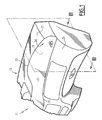
- FIG. 3 describes a first dashboard 11 according to the invention.
- this board 11 comprises a rigid support frame 13 which internally delimits a housing 15, and a flexible lining 17 comprising a peripheral region 19 for attachment to the frame 13.
- the flexible lining 17 completely blocks housing 15.
- the support frame 13, sometimes called insert, is fixed in a conventional manner to the body (not shown) of the motor vehicle. It is made for example of polyolefin thermoplastic material, homopolymer or copolymer, optionally comprising mineral fillers or a reinforcement by glass fibers. It can be made of ABS-PC (acrylonitrile butadiene styrene and polycarbonate) optionally reinforced with glass fibers. These materials have a rigidity to fulfill a support function.
- the armature 13 comprises an upper wall 21 and a lower wall 23, interconnected by a hollow region delimiting the housing 15.
- the upper and lower walls 21 and 23 are curved. Each wall 21, 23 has an outer surface 24A, 24B which partially delimits an appearance surface 26 of the dashboard 11 intended to be placed opposite a vehicle occupant.
- the hollow region 25 comprises front and rear walls 27 and 29 for connection to the lining, and a bottom 31 which connects the walls 27 and 29.
- the connecting walls 27 and 29 extend downward substantially perpendicular to the upper and lower walls 21 and 23 respectively.
- the walls 27 and 29 define respectively with the upper and lower walls 21 and 23 a front shoulder 33 and a rear shoulder 35 which extend transversely facing each other, as shown in Figure 1.
- the bottom 31 extends between the lower edges 37 and 39 of the connecting walls 27 and 29, parallel to the surface of appearance 26 of the dashboard 11.
- passages 41 of the peripheral region 19 are formed in the bottom 31, in the vicinity respectively of the connecting walls 27 and 29. These passages 41 extend substantially transversely along the connecting walls 27, 29.
- the hollow region 25 comprises lining walls 43 and 45 which protrude upwards from the bottom 31.
- Each clasping wall 43, 45 extends transversely facing a connecting wall 27, 29 associated parallel to this connecting wall 27, 29, over substantially the entire length of this wall.
- each wall 43, 45, taken perpendicular to the appearance surface is less than the height of the connecting wall 27, 29 facing.
- Each clasping wall 43, 45 forms with its connecting wall 27, 29 opposite a clamp 47, 49 of the fastening region 19 of the lining, as will be described below.
- the passages 41 open into the clamps 47, 49.
- the flexible lining 17 comprises an external covering skin 51 extended downwards by a network of supporting ribs 53 delimiting between them cavities 55.
- the lining 17 and thus the skin 51 and the ribs 53 are formed in one piece of plastic material, for example elastomeric thermoplastic such as thermoplastic polyurethane (TPU), thermoplastic polyolefin (TPO). It is also possible to use flexible polyvinyl chloride (PVC) or rubber such as silicone.
- plastic material for example elastomeric thermoplastic such as thermoplastic polyurethane (TPU), thermoplastic polyolefin (TPO).
- TPU thermoplastic polyurethane
- TPO thermoplastic polyolefin
- PVC polyvinyl chloride
- silicone silicone
- the lining 17 is significantly softer than the armature 13.
- the flexible material used to form the lining 17 of Figures 1 to 3 is for example translucent as shown in Figure 2.
- the ribs 53 extend from a lower surface 57 of the skin 51 to an upper surface 59 of the bottom 31 on which it rests. Note that, in this example, the ribs 53 are substantially orthogonal to the leading surfaces of the bottom 31 and the skin 17.
- the lining 17 being made of a flexible material and cells 55 being delimited between the ribs 53, the lining 17 can be deformed to the touch.
- This deformation can result from a buckling of the ribs 53 situated in the vicinity of the point of application of a thrust force and a flexion of the skin region or regions 51 located between these ribs 53.
- the ribs 53 and the cells 55 thus confer its flexibility and thickness to the lining 17 so that a satisfactory comfort is obtained.
- the upper surface 58 of the skin 51 is flush with each outer surface 24A, 24B, facing the connecting walls 27, 29.
- the appearance surface 26 of the dashboard is thus continuous along the front and rear shoulders 33 and 35. .
- the peripheral region 19 comprises a front binding rib 61 and a rear binding rib 63 respectively disposed in the clamps 47 and 49.
- Each fixing rib 61, 63 protrudes downwardly in the housing 15 relative to the skin 51, perpendicularly to the directing surface of the skin 51.
- the ribs 61, 63 extend transversely over substantially the entire length of the skin. respective connecting walls 27, 29.
- the fixing ribs 61, 63 externally delimit the lining, so that in vertical section, no part of the skin 51 extends beyond the ribs 61, 63.
- the ribs 61, 63 are of similar structures so that only the rib 61 will be described in what follows.
- the rib 61 comprises, from top to bottom, an upper portion 65 disposed in the associated fastening clamp 47, a thinned intermediate portion 67 disposed in the fastening passage 41 at the bottom of the clamp 47, and a lower conical fixing portion 69 resting on a lower surface 70 of the bottom 31.
- the upper part 65 extends between the connecting wall 27 and the clasping wall 43 opposite, along the connecting wall 27. At rest, when the lining 17 is disposed away from the frame 13 , the thickness of the upper portion 65 is slightly greater than the distance between the clasping wall 43 of the connecting wall 27. Thus, when the rib 61 is inserted into the clamp 47, the upper portion 65 is clamped between the walls 27 and 43 to ensure a continuous blocking of the packing 17 along the wall 27.
- the thickness of the intermediate portion 67 is smaller than the thickness of the upper portion 65.
- the intermediate portion 61 also has dimensions substantially conjugate to those of the passage 41.
- the lower portion 69 is of substantially conical shape, converging downwards.
- the width of a base of the cone delimiting the portion 69 is greater than the width of the passage 41.
- a tongue 71 of traction extends the lower part 69 downwards from the top of the cone.
- the fastening rib 61 is introduced from top to bottom in its associated fastener 47.
- the fastening tongue 71 is inserted into the passage 41.
- the tongue 71 is pulled down, and the lower portion 69 is forced into the passage 41 by compression.
- the thickness of the upper part 65 is reduced and the upper part 65 forcibly enters the fixing clamp 47.
- intermediate fixing ribs 73 structures similar to the fastening ribs 61, 63 of the peripheral region are provided in a central region of the lining 17. These ribs 73 are inserted into passages secondary fasteners 75 formed in the bottom 31.
- the intermediate fixing rib 73 is also clamped in a clamping clamp formed by two gripping walls projecting outwardly relative to the bottom of the housing.
- a rib provides effective fixation of the lining on the frame in the angular regions of the frame.
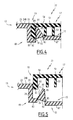
- the second dashboard 77 according to the invention partially shown in Figures 4 and 5 differs from the first board 11 in that the clasping walls 43, 45 are movable respectively relative to the connecting walls 27, 29 opposite, between an open insertion position of the lining shown in FIG. 5, and a closed fastening position of the lining shown in FIG. 4.
- the clasping walls 43, 45 are movable relative to the connecting walls 27, 29 respectively. look at a substantially constant temperature.
- the clasping wall 45 is articulated along a rear lower edge 81 to a peripheral portion 83 of the bottom 31 integral with the connecting wall 29.
- the clasping wall 45 is articulated by a front lower edge 85 to a central portion 87 of the bottom 31 movable relative to the peripheral portion 83 between a lower position shown in FIG. 5, in which the central portion 87 is located under the peripheral portion 83 and an upper position shown in Figure 4, in which the central portion 87 is located above the peripheral portion 83.
- Articulations between the clasping wall 45 and the peripheral portions 83 and 87 of the bottom 31 are for example formed by plastic hinges which extend transversely along the connecting wall 29.
- a gripping surface 89 of the movable wall 45 situated opposite the connecting wall 29 delimits a hollow region 91 adjacent to the lower edge 81.
- the fixing rib 63 is devoid of thinned intermediate portion and tapered lower portion.
- the fastening rib 63 comprises, at its lower end, a bead 92 projecting towards the inside of the housing 15.
- the surface 89 is disposed away from the connecting wall 29 and delimits with this wall 29 a cavity opening divergingly upwards.
- the lower front edge 85 is located below the rear lower edge 81.
- the hollow region 91 does not form an undercut portion so that its demolding is facilitated when the armature 12 is made in one piece by injection.
- the surface 89 extends substantially parallel to the connecting wall 29. In this position, the central portion 87 of the bottom 31 is in its upper position.
- the hollow region 91 forms an undercut portion which cooperates with the inner bead 92 at the lower end of the fastening rib 63.
- the distance between the lower rear edge 81 of the front lower edge 85, taken along a lower surface 93 of the clasping wall 45 is less than the distance between the peripheral portion 83 of the central portion 87 of the bottom 31 , taken perpendicular to the wall 29.
- the fixing clip 49 is first placed in its open position of insertion of the packing 17 shown in Figure 5.
- the central portion 87 of the bottom 31 is then in its lower position.
- the lining 17 is then brought into the housing 15.
- the fastening rib 63 is placed on the peripheral portion 83 of the bottom 31, between the connecting wall 29 and the clasping wall 49.
- the movable portion 87 of the bottom 31 is then push up to move to its upper position.
- the lining 17 is then firmly fixed in the housing 19.
- the outer surface 58 of the lining 17 is flush with the outer surfaces 24A and 24B of the upper and lower walls 21 and 23.
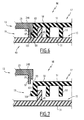
- the third dashboard according to the invention 96 shown in Figures 6 and 7 differs from the first dashboard 11 in that the bottom 31 is attached to the lower end 39 of the connecting wall 29 by snapping or welding. Only the rear clamp 49 and the associated binding rib 63 are shown in these figures.
- the lower edge 39 of the connecting wall 29 delimits internally towards the housing 15 a recess for fixing the fixing rib 63.
- the rib 63 is devoid of intermediate portion and lower portion. It comprises at its lower end a bead 101 directed towards the outside of the housing 15.
- the bottom 31 and the clasping wall 45 are movable relative to the connecting wall 29, between an open insertion position of the lining 17 shown in FIG. 7, in which the bottom 31 is disposed away from the connecting wall 27, and a closed position for fixing the lining 17, in which the bottom 31 is attached to the connecting wall 27.
- the fixing position the bead 101 is received in the recess 99.
- rib 63 is sandwiched between the connecting wall 29 and the clasping wall 45.
- the lining 17 is disposed on the bottom 31.
- the fixing rib 63 is applied against the clasping wall 45 outside of the wall 45.
- the rib 63 is placed on the bottom 31, outside the wall 45.
- the lining 17 and the bottom 31 are moved towards the connecting wall 27.
- the rib 63 is then clamped between the connecting wall 29 and the clasping wall 45.
- the outer bead 101 is received in the housing. recess 99 to prevent detachment of the lining 17 along an axis perpendicular to the appearance surface of the skin.
- the bottom 31 is then fixed by welding or snapping on the wall 29.
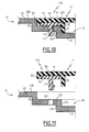
- the fourth dashboard 102 differs from the first dashboard 11 in that the clasping wall 45 is integral with a support 103 snap in the bottom 31 of the hollow region 25.
- the support 103 has a substantially flat base 105 and an outer region 107 in the form of a step at the end of which the wall 45 projects upwards.
- a snap lug 109 projects downwardly from the base 105.
- the support 103 and the gripping wall 45 are thus movable relative to the connecting wall 29 between an open position of insertion of the packing in which they are arranged away from the bottom 31, and a closed position of connection in which they are fixed in the bottom 31.
- the fastening rib 63 comprises, at its lower end, an inner bead 113 which protrudes towards the inside of the housing 15.
- the bottom 31 delimits a cavity 114 for receiving the base 105.
- a passage 115 for snapping through opens into the cavity 114.
- the support 103 and the clasping wall 45 are initially in the open position.
- the wall 45 is inserted into the undercut region defined by the fastening rib 63 and the bead 113.
- the bead 113 is then engaged under the step 107.
- the bearing rib 53 adjacent to the fastening rib 63 is wedged above the step 107.
- the lug 109 is inserted into the ratchet opening 115 and the base 105 is received in the cavity 114.
- the fixing rib 63 is clamped between the clasping wall 45 and the connecting wall 27.
- the bead 113 is wedged between the step 107 and the bottom 31.
- the fifth dashboard 116 differs from the first dashboard 11 in that the rigid cladding wall 45 is fixed to the lining 17 between the fixing rib 63 and the support rib. 53, before the insertion of the lining 17 in the housing 15.
- the height of the fastening rib 63 is less than the height of the support rib 53.
- the clasping wall 45 comprises a tab lug 117 which projects downwards.
- the clasping wall 45 is made for example by injection molding on the lining 17.
- the bottom 31 delimits a peripheral step 119 in the vicinity of the connecting wall 29.
- This step 119 delimits a through opening 121 which opens into its upper surface 123.
- the clasping wall 25 is movable relative to the connecting wall 29 between an open insertion position of the lining away from the bottom 31 and a closed position of connection, in which it is fixed in the bottom 31.
- the clasping wall 45 integral with the lining 17 is initially disposed in its open position away from the connecting wall 29 and the bottom 31.
- the latching lug 117 is inserted into the corresponding passage 121.
- the clasping wall 45 is placed on the upper surface 123 of the step 119, perpendicular to the connecting wall 29.
- the rib 63 is then clamped between the connecting wall 29 and the clasping wall 45.
- the rib adjacent bearing 53 is wedged against a lateral surface 125 of the step 119 perpendicular to the upper surface 123.
- a piece of motor vehicle equipment comprising a rigid frame 13 and a flexible lining 17 received in a housing 15 defined by the frame 13, in which the fixing of the lining 17 on the frame 13 is robust, and preserves the aesthetic appearance of the part obtained after fixing.
- the assembly of the lining 17 on the frame 13 is facilitated when the clamp 47, 49 comprises two walls movable relative to each other between an open position of placement of the lining 17 and a closed fastening position .
Landscapes
- Engineering & Computer Science (AREA)
- Mechanical Engineering (AREA)
- Chemical & Material Sciences (AREA)
- Combustion & Propulsion (AREA)
- Transportation (AREA)
- Vehicle Interior And Exterior Ornaments, Soundproofing, And Insulation (AREA)
- Automobile Manufacture Line, Endless Track Vehicle, Trailer (AREA)
- Body Structure For Vehicles (AREA)
Applications Claiming Priority (1)
| Application Number | Priority Date | Filing Date | Title |
|---|---|---|---|
| FR0503653A FR2884202B1 (fr) | 2005-04-12 | 2005-04-12 | Piece d'equipement pour vehicule automobile et procede de montage associe. |
Publications (2)
| Publication Number | Publication Date |
|---|---|
| EP1712429A2 true EP1712429A2 (de) | 2006-10-18 |
| EP1712429A3 EP1712429A3 (de) | 2007-06-20 |
Family
ID=35063217
Family Applications (1)
| Application Number | Title | Priority Date | Filing Date |
|---|---|---|---|
| EP06290586A Withdrawn EP1712429A3 (de) | 2005-04-12 | 2006-04-11 | Auto-Innenausstattungsteil und dazu gehöriges Montageverfahren |
Country Status (2)
| Country | Link |
|---|---|
| EP (1) | EP1712429A3 (de) |
| FR (1) | FR2884202B1 (de) |
Cited By (3)
| Publication number | Priority date | Publication date | Assignee | Title |
|---|---|---|---|---|
| EP2022660A1 (de) * | 2007-08-01 | 2009-02-11 | Ford Global Technologies, LLC | Automobilarmaturensystem |
| EP3228503A4 (de) * | 2014-12-05 | 2018-05-30 | Toyoda Iron Works Co., Ltd. | Innenverkleidung für ein fahrzeug |
| US10293762B2 (en) | 2014-11-26 | 2019-05-21 | Toyota Iron Works Co., Ltd. | Vehicular interior component, vehicular interior panel, and vehicular composite interior component |
Families Citing this family (3)
| Publication number | Priority date | Publication date | Assignee | Title |
|---|---|---|---|---|
| PL232922B1 (pl) * | 2017-09-12 | 2019-08-30 | Zamel Spolka Z Ograniczona Odpowiedzialnoscia | Sposób łączenia ramek opraw oświetleniowych |
| JP2024084395A (ja) * | 2022-12-13 | 2024-06-25 | 株式会社Subaru | 車両の座席前のパネル部材 |
| JP2024084396A (ja) * | 2022-12-13 | 2024-06-25 | 株式会社Subaru | 車両の座席前のパネル部材 |
Family Cites Families (5)
| Publication number | Priority date | Publication date | Assignee | Title |
|---|---|---|---|---|
| US5813693A (en) * | 1996-02-26 | 1998-09-29 | Trw Vechiclesafety Systems Inc. | Releasable attachment for air bag deployment door |
| JP2000043614A (ja) * | 1998-07-28 | 2000-02-15 | Inoac Corp | インストルメントパネル |
| DE10047271A1 (de) * | 2000-09-23 | 2002-04-11 | Volkswagen Ag | Säulenverkleidung im Innenraum eines Kraftfahrzeuges |
| US6581958B2 (en) * | 2001-04-17 | 2003-06-24 | Autoliv Asp, Inc. | Energy managed airbag cover |
| FR2828856B1 (fr) * | 2001-08-22 | 2003-12-05 | Sai Automotive Allibert Ind | Dispositif destine a masquer les jeux entre une planche de bord et un element d'habillage lie a une colonne de direction reglable |
-
2005
- 2005-04-12 FR FR0503653A patent/FR2884202B1/fr not_active Expired - Fee Related
-
2006
- 2006-04-11 EP EP06290586A patent/EP1712429A3/de not_active Withdrawn
Cited By (5)
| Publication number | Priority date | Publication date | Assignee | Title |
|---|---|---|---|---|
| EP2022660A1 (de) * | 2007-08-01 | 2009-02-11 | Ford Global Technologies, LLC | Automobilarmaturensystem |
| US7735905B2 (en) | 2007-08-01 | 2010-06-15 | Ford Global Technologies, Llc | Automotive vehicle instrument panel system |
| US10293762B2 (en) | 2014-11-26 | 2019-05-21 | Toyota Iron Works Co., Ltd. | Vehicular interior component, vehicular interior panel, and vehicular composite interior component |
| EP3228503A4 (de) * | 2014-12-05 | 2018-05-30 | Toyoda Iron Works Co., Ltd. | Innenverkleidung für ein fahrzeug |
| US10059282B2 (en) | 2014-12-05 | 2018-08-28 | Toyoda Iron Works Co., Ltd. | Vehicular interior panel |
Also Published As
| Publication number | Publication date |
|---|---|
| EP1712429A3 (de) | 2007-06-20 |
| FR2884202A1 (fr) | 2006-10-13 |
| FR2884202B1 (fr) | 2007-06-29 |
Similar Documents
| Publication | Publication Date | Title |
|---|---|---|
| EP2352925B1 (de) | Verfahren zur montage eines teiles auf einem profilstrang, vorrichtung zur zwischenbefestigung eines teiles auf einem profilstrang, verglasung und verwendung einer solchen vorrichtung | |
| JP4054892B2 (ja) | 車両用ドアの車内側ウエザーストリップ | |
| EP2750935B1 (de) | Fahrzeugsicherheitsvorrichtung | |
| US8001727B2 (en) | Sealing molding with insert for forming closeout surface | |
| JP2015502291A (ja) | 固定された車両のウィンドウガラスに部品を接合するための成形要素 | |
| FR2585638A1 (fr) | Panneau de plafond coulissant pour toit ouvrant de vehicule automobile | |
| EP2900499B1 (de) | Verglasung mit verkapselter profildichtung und angeschlossener komponente an der dichtung, befestigungselement für die verglasung befestigter komponenten und verfahren zur herstellung der verglasung | |
| EP3655271B1 (de) | Verglasungseinheit mit schieberille und verfahren zur herstellung der verglasungseinheit | |
| US10081394B2 (en) | Mounting structure of vehicular resin component | |
| FR2884202A1 (fr) | Piece d'equipement pour vehicule automobile et procede de montage associe. | |
| EP2015968A1 (de) | Auskleidung für eine kraftfahrzeugkomponente und entsprechende komponente | |
| WO2007128921A1 (fr) | Piece d'equipement pour vehicule automobile et vehicule automobile associe | |
| JP2005271659A (ja) | 自動車用ガラスラン | |
| JP2003104068A (ja) | ウエザーストリップの取付構造 | |
| WO2011095746A2 (fr) | Ensemble d'équipement de véhicule automobile et procédé de montage associé | |
| EP2785563B1 (de) | Anordnung einer lateralen auskleidung für einen gepäckraum | |
| EP3720738B1 (de) | Verkleidung für fahrzeugtürrahmen | |
| EP1798112B1 (de) | Verfahren zum Spritzgiessen eines Ausstattungsteiles sowie danach hergestelltes Ausstattungsteil | |
| FR2869005A1 (fr) | Piece d'equipement pour vehicule automobile, procede de realisation et vehicule automobile associes. | |
| EP1095762A1 (de) | Verfahren zur Herstellung einer Verbundplatte, insbesondere ein Fahrzeugdach oder Fussboden eines industriellen Fahrzeugs sowie nach diesem Verfahren hergestellte Platte | |
| WO2020229741A1 (fr) | Butée de surclaquage pour capot de véhicule automobile | |
| JP4250842B2 (ja) | 自動車用部品の固定構造 | |
| JP4735232B2 (ja) | ウエザストリップ及びその製造方法 | |
| EP2246212B1 (de) | Fahrzeugklappe mit einem Dichtungselement | |
| EP4725773A1 (de) | Frontstossfängerbaugruppe für ein kraftfahrzeug |
Legal Events
| Date | Code | Title | Description |
|---|---|---|---|
| PUAI | Public reference made under article 153(3) epc to a published international application that has entered the european phase |
Free format text: ORIGINAL CODE: 0009012 |
|
| AK | Designated contracting states |
Kind code of ref document: A2 Designated state(s): AT BE BG CH CY CZ DE DK EE ES FI FR GB GR HU IE IS IT LI LT LU LV MC NL PL PT RO SE SI SK TR |
|
| AX | Request for extension of the european patent |
Extension state: AL BA HR MK YU |
|
| PUAL | Search report despatched |
Free format text: ORIGINAL CODE: 0009013 |
|
| AK | Designated contracting states |
Kind code of ref document: A3 Designated state(s): AT BE BG CH CY CZ DE DK EE ES FI FR GB GR HU IE IS IT LI LT LU LV MC NL PL PT RO SE SI SK TR |
|
| AX | Request for extension of the european patent |
Extension state: AL BA HR MK YU |
|
| 17P | Request for examination filed |
Effective date: 20071121 |
|
| 17Q | First examination report despatched |
Effective date: 20071220 |
|
| AKX | Designation fees paid |
Designated state(s): DE ES FR |
|
| STAA | Information on the status of an ep patent application or granted ep patent |
Free format text: STATUS: THE APPLICATION IS DEEMED TO BE WITHDRAWN |
|
| 18D | Application deemed to be withdrawn |
Effective date: 20081103 |