EP1712496A1 - Dispositif de prehension d'un recipient avec maintien d'une partie epaulee de celui-ci - Google Patents
Dispositif de prehension d'un recipient avec maintien d'une partie epaulee de celui-ci Download PDFInfo
- Publication number
- EP1712496A1 EP1712496A1 EP06290560A EP06290560A EP1712496A1 EP 1712496 A1 EP1712496 A1 EP 1712496A1 EP 06290560 A EP06290560 A EP 06290560A EP 06290560 A EP06290560 A EP 06290560A EP 1712496 A1 EP1712496 A1 EP 1712496A1
- Authority
- EP
- European Patent Office
- Prior art keywords
- jaws
- container
- neck
- support member
- gripping
- Prior art date
- Legal status (The legal status is an assumption and is not a legal conclusion. Google has not performed a legal analysis and makes no representation as to the accuracy of the status listed.)
- Withdrawn
Links
- 239000000463 material Substances 0.000 abstract description 2
- 239000012611 container material Substances 0.000 description 1
- 238000009434 installation Methods 0.000 description 1
- 230000035515 penetration Effects 0.000 description 1
- 230000000284 resting effect Effects 0.000 description 1
- 230000000717 retained effect Effects 0.000 description 1
- 238000007789 sealing Methods 0.000 description 1
Images

Classifications
-
- B—PERFORMING OPERATIONS; TRANSPORTING
- B67—OPENING, CLOSING OR CLEANING BOTTLES, JARS OR SIMILAR CONTAINERS; LIQUID HANDLING
- B67B—APPLYING CLOSURE MEMBERS TO BOTTLES JARS, OR SIMILAR CONTAINERS; OPENING CLOSED CONTAINERS
- B67B3/00—Closing bottles, jars or similar containers by applying caps
- B67B3/20—Closing bottles, jars or similar containers by applying caps by applying and rotating preformed threaded caps
- B67B3/206—Means for preventing rotation of the container or cap
-
- B—PERFORMING OPERATIONS; TRANSPORTING
- B65—CONVEYING; PACKING; STORING; HANDLING THIN OR FILAMENTARY MATERIAL
- B65G—TRANSPORT OR STORAGE DEVICES, e.g. CONVEYORS FOR LOADING OR TIPPING, SHOP CONVEYOR SYSTEMS OR PNEUMATIC TUBE CONVEYORS
- B65G29/00—Rotary conveyors, e.g. rotating discs, arms, star-wheels or cones
-
- B—PERFORMING OPERATIONS; TRANSPORTING
- B65—CONVEYING; PACKING; STORING; HANDLING THIN OR FILAMENTARY MATERIAL
- B65G—TRANSPORT OR STORAGE DEVICES, e.g. CONVEYORS FOR LOADING OR TIPPING, SHOP CONVEYOR SYSTEMS OR PNEUMATIC TUBE CONVEYORS
- B65G47/00—Article or material-handling devices associated with conveyors; Methods employing such devices
- B65G47/74—Feeding, transfer, or discharging devices of particular kinds or types
- B65G47/84—Star-shaped wheels or devices having endless travelling belts or chains, the wheels or devices being equipped with article-engaging elements
- B65G47/846—Star-shaped wheels or wheels equipped with article-engaging elements
- B65G47/847—Star-shaped wheels or wheels equipped with article-engaging elements the article-engaging elements being grippers
-
- B—PERFORMING OPERATIONS; TRANSPORTING
- B65—CONVEYING; PACKING; STORING; HANDLING THIN OR FILAMENTARY MATERIAL
- B65G—TRANSPORT OR STORAGE DEVICES, e.g. CONVEYORS FOR LOADING OR TIPPING, SHOP CONVEYOR SYSTEMS OR PNEUMATIC TUBE CONVEYORS
- B65G2201/00—Indexing codes relating to handling devices, e.g. conveyors, characterised by the type of product or load being conveyed or handled
- B65G2201/02—Articles
- B65G2201/0235—Containers
- B65G2201/0244—Bottles
-
- B—PERFORMING OPERATIONS; TRANSPORTING
- B65—CONVEYING; PACKING; STORING; HANDLING THIN OR FILAMENTARY MATERIAL
- B65G—TRANSPORT OR STORAGE DEVICES, e.g. CONVEYORS FOR LOADING OR TIPPING, SHOP CONVEYOR SYSTEMS OR PNEUMATIC TUBE CONVEYORS
- B65G2201/00—Indexing codes relating to handling devices, e.g. conveyors, characterised by the type of product or load being conveyed or handled
- B65G2201/02—Articles
- B65G2201/0235—Containers
- B65G2201/0244—Bottles
- B65G2201/0247—Suspended bottles
-
- B—PERFORMING OPERATIONS; TRANSPORTING
- B65—CONVEYING; PACKING; STORING; HANDLING THIN OR FILAMENTARY MATERIAL
- B65G—TRANSPORT OR STORAGE DEVICES, e.g. CONVEYORS FOR LOADING OR TIPPING, SHOP CONVEYOR SYSTEMS OR PNEUMATIC TUBE CONVEYORS
- B65G51/00—Conveying articles through pipes or tubes by fluid flow or pressure; Conveying articles over a flat surface, e.g. the base of a trough, by jets located in the surface
- B65G51/02—Directly conveying the articles, e.g. slips, sheets, stockings, containers or workpieces, by flowing gases
- B65G51/03—Directly conveying the articles, e.g. slips, sheets, stockings, containers or workpieces, by flowing gases over a flat surface or in troughs
- B65G51/035—Directly conveying the articles, e.g. slips, sheets, stockings, containers or workpieces, by flowing gases over a flat surface or in troughs for suspended articles, e.g. bottles
Definitions
- the present invention relates to a device for gripping containers which can be used in particular in container sealing installations.
- Containers more particularly concerned comprise a body having a shoulder portion surmounted by a neck having a projecting flange.
- a gripping device for such containers generally comprises a support member having a lateral opening for receiving a portion of the neck and forming a support for the flange and two jaws mounted movable relative to the support member for clamping the neck or the collar in order to hold the container on the support element.
- a gripping device comprising a support member having a lateral opening for receiving a portion of the neck and a projecting upper surface of which point or sharp blades extend to bite the underside of the collar.
- An external guide holds the neck in the lateral opening.
- the screwing head carrying the cap is applied to the neck so as to exert on the neck a sufficient force to ensure the penetration of the tips or blades in the collar and prevent rotation of the container during screwing.
- the pressure exerted by the screwing head generates a relatively large friction of the cap on the neck. This friction increases the torque resistant to screwing the plug and is difficult to control, making it difficult to obtain uniform tightening torques.
- An object of the invention is to provide a simple means for effectively maintaining the container without acting on the upper part of the neck of the container.
- a device for gripping a container comprising a shoulder portion surmounted by a neck having a projecting flange, the device comprising a support element having a lateral opening for receiving a part of the neck and form a support for the flange, two jaws being mounted movable relative to the support member to maintain the container on the support member, the jaws extending under the support member and having a lower face of support on the shoulder part of the container.
- the jaws exert on the shoulder portion a force tending to apply the collar on the support member while maintaining the neck in the lateral opening of the support member.
- the gripping device that will be described is intended for holding containers generally designated 1, having a shoulder portion 2 surmounted by a neck 3 having a flange 4 extending projecting.
- the gripping device generally designated at 10, comprises a rigid support member 11 having a lateral opening 12 arranged to receive the part of the neck extending under the flange, the flange resting on an upper face 13 of the support element. 11.
- the gripping device also comprises two jaws, generally designated at 14, 15, connected to the support element 11 by a hinge pin 16 so that the jaws 14, 15 extend under the support element and are movable. between an open position and a closed position.
- Each jaw 14, 15 here has a curved shape and has a lower housing 17, 18 for receiving a lining 19, 20 having a truncated cone segment surface 28, 29 for forming a lower surface of the jaw 14, 15.
- the lining 19, 20 is retained in the lower housing 17, 18 by a plate 21, 22 screwed under the jaw 14, 15.
- the jaw 14 extends beyond the axis of articulation 16 by an appendage 23 supporting a pivoting roller 24 of axis parallel to the hinge axis 16 of the jaws.
- the pivoting roller 24 extends above the appendage 23.
- the plate 22 of the jaw 15 extends beyond the axis of articulation by an appendage 25 carrying a pivoting roller 26 of axis parallel to the articulation pin 16.
- the pivoting roller 26 extends below appendix 25.
- the gripping device further comprises a resilient return member of the jaws in the open position.
- the elastic return member here is a helical torsion spring 27 centered on the hinge pin 16 and having integral end portions of the jaws 14, 15.
- FIG. 2 shows a platform 30 mounted in a manner known per se for pivoting on a frame that is not shown and provided with a plurality of gripping devices 10.
- the gripping devices 10 are fixed under the platform 30 by the hinge axis 16, the support member 11 being immobilized in rotation relative to the platform.
- a cam 31 is fixed to the frame to extend under the platform.
- the cam 31 comprises two superimposed profiles for cooperating respectively with the pivoting rollers 24, 26 so as to bring the jaws 14, 15 from their open position (visible in FIG. 1 on the gripping device 10 carrying the index a) towards their closed position (visible in Figure 1 on the gripper 10 bearing the index b).
- the fittings are made of a relatively flexible material to improve the contact of the gaskets with the shoulder portion and adhering to the container material to prevent rotation of the container. This is all the more advantageous as the lower surface of the jaws in contact with the shoulder portion is large, which limits the application force of the flange on the support member.
- the ends of the jaws here advantageously bear on the shoulder portion 2 on one side thereof opposite the support member 11, which tends to push the neck 3 in the lateral opening 12 of the element support 11.
- the roller 24 of the gripping device considered is located above the roller 26 of the gripping device adjacent to the jaw 14 of the gripping device considered while, on the other side, the roller 26 of the device This gripping device is located below the roller 24 of the gripping device adjacent to the jaw 15 of the gripping device in question. It is thus possible to make a platform with particularly close gripping devices.
- the jaws may have different structures from those described.
- the appendages supporting the pivoting rollers may be in the same plane.
- the control means of the jaws may be other than a cam and comprise an actuator, such as a jack, associated with each gripping device.
- bearing surfaces on the shoulder portions can be made directly on the jaws.
- the bearing surfaces may have different shapes from those described, these forms favoring the application of a force downwards by the jaws on the shoulder portion during the closure of the jaws. These surfaces act as a cam on the shouldered portion to apply the flange to the support member.
- sharp reliefs may be provided on the upper surface of the support member to bite into the flange of the container under the force exerted by the jaws.
- the gaskets may then have a lower coefficient of friction on the container.
Landscapes
- Engineering & Computer Science (AREA)
- Mechanical Engineering (AREA)
- Sealing Of Jars (AREA)
Abstract
Description
- La présente invention concerne un dispositif de préhension de récipients qui est utilisable notamment dans les installations de bouchage de récipients. Les récipients plus particulièrement concernés comportent un corps possédant une partie épaulée surmontée d'un goulot ayant une collerette en saillie.
- Un dispositif de préhension de tels récipients comporte généralement un élément support présentant une ouverture latérale pour recevoir une partie du goulot et former un appui pour la collerette et deux mâchoires montées mobiles par rapport à l'élément support pour serrer le goulot ou la collerette afin de maintenir le récipient sur l'élément support. Ces dispositifs de préhension sont d'utilisation délicate notamment dans les installations de bouchage de récipients où l'espace disponible autour du goulot est relativement restreint pour ne pas gêner la mise en place du bouchon sur le goulot du récipient.
- Pour les bouteilles en matière plastique, il est connu un dispositif de préhension comportant un élément support présentant une ouverture latérale pour recevoir une partie du goulot et une face supérieure en saillie de laquelle s'étendent des pointes ou des lames acérées pour mordre le dessous de la collerette. Un guide externe maintient le goulot dans l'ouverture latérale. Lors du vissage, la tête de vissage portant le bouchon est appliquée sur le goulot de manière à exercer sur le goulot un effort suffisant pour assurer la pénétration des pointes ou des lames dans la collerette et empêcher la rotation du récipient lors du vissage. Cependant, la pression exercée par la tête de vissage engendre une friction relativement importante du bouchon sur le goulot. Cette friction augmente le couple résistant au vissage du bouchon et est difficilement maîtrisable, rendant délicate l'obtention de couples de serrage homogènes.
- Un but de l'invention est de fournir un moyen simple permettant un maintien efficace du récipient sans agir sur la partie supérieure du goulot du récipient.
- A cet effet, on prévoit, selon l'invention, un dispositif de préhension d'un récipient comportant une partie épaulée surmontée d'un goulot ayant une collerette en saillie, le dispositif comportant un élément support présentant une ouverture latérale pour recevoir une partie du goulot et former un appui pour la collerette, deux mâchoires étant montées mobiles par rapport à l'élément support pour assurer un maintien du récipient sur l'élément support, les mâchoires s'étendant sous l'élément support et comportant une face inférieure d'appui sur la partie épaulée du récipient.
- Ainsi, les mâchoires exercent sur la partie épaulée un effort tendant à appliquer la collerette sur l'élément support tout en maintenant le goulot dans l'ouverture latérale de l'élément support.
- D'autres caractéristiques et avantages de l'invention ressortiront à la lecture de la description qui suit d'un mode de réalisation particulier non limitatif de l'invention.
- Il sera fait référence aux dessins annexés parmi lesquels :
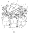
- la figure 1 est une vue partielle en perspective, avec écorché, d'une plate-forme équipée de dispositifs de préhension conformes à l'invention.
- la figure 2 est une vue éclatée en perspective d'un tel dispositif de préhension.
- En référence aux figures, le dispositif de préhension qui va être décrit est destiné au maintien de récipients généralement désigné en 1, comportant une partie épaulée 2 surmontée d'un goulot 3 ayant une collerette 4 s'étendant en saillie.
- Le dispositif de préhension, généralement désigné en 10, comprend un élément support 11, rigide, présentant une ouverture latérale 12 agencée pour recevoir la partie du goulot s'étendant sous la collerette, la collerette reposant sur une face supérieure 13 de l'élément support 11.
- Le dispositif de préhension comprend également deux mâchoires, généralement désignées en 14, 15, reliées à l'élément support 11 par un axe d'articulation 16 de telle manière que les mâchoires 14, 15 s'étendent sous l'élément support et soient mobiles entre une position ouverte et une position fermée.
- Chaque mâchoire 14, 15 a ici une forme recourbée et présente un logement inférieur 17, 18 pour recevoir une garniture 19, 20 ayant une surface 28, 29 en segment de tronc de cône destinée à former une surface inférieure de la mâchoire 14, 15. La garniture 19, 20 est retenue dans le logement inférieur 17, 18 par une plaque 21, 22 vissée sous la mâchoire 14, 15. La mâchoire 14 se prolonge au-delà de l'axe d'articulation 16 par un appendice 23 supportant un galet pivotant 24 d'axe parallèle à l'axe d'articulation 16 des mâchoires. Le galet pivotant 24 s'étend au-dessus de l'appendice 23. La plaque 22 de la mâchoire 15 se prolonge au-delà de l'axe d'articulation par un appendice 25 portant un galet pivotant 26 d'axe parallèle à l'axe d'articulation 16. Le galet pivotant 26 s'étend en-dessous de l'appendice 25.
- Le dispositif de préhension comprend en outre un organe de rappel élastique des mâchoires en position ouverte. L'organe de rappel élastique est ici un ressort hélicoïdal de torsion 27 centré sur l'axe d'articulation 16 et ayant des portions d'extrémité solidaires des mâchoires 14, 15.
- Il est représenté à la figure 2 une plate-forme 30 montée de façon connue en elle-même pour pivoter sur un bâti non représenté et pourvue d'une pluralité de dispositifs de préhension 10.
- Les dispositifs de préhension 10 sont fixés sous la plate-forme 30 par l'axe d'articulation 16, l'élément support 11 étant immobilisé en rotation par rapport à la plate-forme.
- Une came 31 est fixée au bâti pour s'étendre sous la plate-forme. La came 31 comporte deux profils superposés pour coopérer respectivement avec les galets pivotants 24, 26 de manière à amener les mâchoires 14, 15 de leur position ouverte (visible à la figure 1 sur le dispositif de préhension 10 portant l'indice a) vers leur position fermée (visible à la figure 1 sur le dispositif de préhension 10 portant l'indice b).
- Lorsque les mâchoires sont fermées, elles exercent sur la partie épaulée un effort dirigé vers le bas qui tend à appliquer la collerette 4 sur la face supérieure 13 de l'élément support 11. Les garnitures sont en un matériau relativement souple pour améliorer le contact des garnitures avec la partie épaulée et adhérant au matériau du récipient pour empêcher une rotation du récipient. Ceci est d'autant plus avantageux que la surface inférieure des mâchoires en contact avec la partie épaulée est grande, ce qui permet de limiter l'effort d'application de la collerette sur l'élément support. En outre, les extrémités des mâchoires prennent ici avantageusement appui sur la partie épaulée 2 d'un côté de celle-ci opposé à l'élément support 11, ce qui tend à pousser le goulot 3 dans l'ouverture latérale 12 de l'élément support 11.
- On notera, en considérant un dispositif de préhension de la figure 1, que comme les galets 24, 26 sont disposés à des niveaux différents, le galet 24 du dispositif de préhension considéré se trouve au-dessus du galet 26 du dispositif de préhension adjacent à la mâchoire 14 du dispositif de préhension considéré tandis que, de l'autre côté, le galet 26 du dispositif de préhension considéré se trouve en dessous du galet 24 du dispositif de préhension adjacent à la mâchoire 15 du dispositif de préhension considéré. Il est ainsi possible de réaliser une plate-forme avec des dispositifs de préhension particulièrement rapprochés.
- Bien entendu, l'invention n'est pas limitée au mode de réalisation décrit et on peut y apporter des variantes de réalisation sans sortir du cadre de l'invention tel que défini par les revendications.
- En particulier, les mâchoires peuvent avoir des structures différentes de celles décrites. Ainsi, lorsque les dispositifs de préhension sont destinés à occuper des positions relativement espacées sur une plate-forme, les appendices supportant les galets pivotants peuvent être dans un même plan. De plus, les moyens de commande des mâchoires peuvent être autres qu'une came et comprendre un actionneur, tel qu'un vérin, associé à chaque dispositif de préhension.
- En outre, les surfaces d'appui sur les parties épaulées peuvent être réalisées directement sur les mâchoires. Les surfaces d'appui peuvent avoir des formes différentes de celles décrites, ces formes favorisant l'application d'un effort vers le bas par les mâchoires sur la partie épaulée lors de la fermeture des mâchoires. Ces surfaces agissent comme une came sur la partie épaulée pour appliquer la collerette sur l'élément support.
- De plus, des reliefs acérés peuvent être prévus sur la surface supérieure de l'élément support pour mordre dans la collerette du récipient sous l'effort exercé par les mâchoires. Les garnitures peuvent alors présenter un plus faible coefficient de frottement sur le récipient.
Claims (6)
- Dispositif de préhension d'un récipient (1) comportant une partie épaulée (2) surmontée d'un goulot (3) ayant une collerette (4) en saillie, le dispositif comportant un élément support (11) présentant une ouverture latérale (12) pour recevoir une partie du goulot et former un appui pour la collerette, deux mâchoires (14, 15) étant montées mobiles par rapport à l'élément support pour assurer un maintien du récipient sur l'élément support, caractérisé en ce que les mâchoires s'étendent sous l'élément support et comportent une surface inférieure (28, 29) d'appui sur la partie épaulée du récipient.
- Dispositif selon la revendication 1, caractérisé en ce que la surface inférieure (28, 29) a une forme en segment de tronc de cône.
- Dispositif selon la revendication 1, caractérisé en ce que la surface inférieure (28, 29) appartient à une garniture (19, 20) montée de façon amovible sur chaque mâchoire (14, 15).
- Dispositif selon la revendication 1, caractérisé en ce qu'il comprend un moyen de rappel élastique (27) des mâchoires (14, 15) en position ouverte.
- Dispositif selon la revendication 1, caractérisé en ce que les mâchoires (14, 15) sont reliées l'une à l'autre par un axe d'articulation (16) et se prolongent au-delà de cet axe d'articulation par des appendices (23, 25) desquels sont solidaires des galets (24, 26) pour coopérer avec au moins une came (31).
- Dispositif selon la revendication 1, caractérisé en ce que la surface inférieure (28, 29) présente un coefficient de frottement suffisant pour permettre une immobilisation en rotation du récipient.
Applications Claiming Priority (1)
| Application Number | Priority Date | Filing Date | Title |
|---|---|---|---|
| FR0503770A FR2884450B1 (fr) | 2005-04-15 | 2005-04-15 | Dispositif de prehension d'un recipient avec maintien d'une partie epaulee de celui-ci |
Publications (1)
| Publication Number | Publication Date |
|---|---|
| EP1712496A1 true EP1712496A1 (fr) | 2006-10-18 |
Family
ID=35456962
Family Applications (1)
| Application Number | Title | Priority Date | Filing Date |
|---|---|---|---|
| EP06290560A Withdrawn EP1712496A1 (fr) | 2005-04-15 | 2006-04-06 | Dispositif de prehension d'un recipient avec maintien d'une partie epaulee de celui-ci |
Country Status (2)
| Country | Link |
|---|---|
| EP (1) | EP1712496A1 (fr) |
| FR (1) | FR2884450B1 (fr) |
Cited By (9)
| Publication number | Priority date | Publication date | Assignee | Title |
|---|---|---|---|---|
| ITTO20100367A1 (it) * | 2010-04-30 | 2011-10-31 | Arol Spa | Dispositivo di presa per macchine tappatrici automatiche |
| EP2653436A1 (fr) * | 2012-04-20 | 2013-10-23 | Krones AG | Dispositif pour recevoir des bouteilles pourvues d'une collerette dans une capsuleuse |
| WO2014043768A1 (fr) | 2012-09-19 | 2014-03-27 | Index-6, Limited Liability Company | Dispositif doté d'éléments de support pouvant être changés pour la préhension et le support de conteneurs |
| CN105540147A (zh) * | 2016-02-04 | 2016-05-04 | 成都泓睿科技有限责任公司 | 液体检测的垂直式输送装置 |
| EP3153417A1 (fr) * | 2015-10-07 | 2017-04-12 | Toyo Jidoki Co., Ltd. | Dispositif préhenseur |
| IT201700047740A1 (it) * | 2017-05-03 | 2018-11-03 | Arol Spa | Dispositivo di presa e centraggio di bottiglie per impianti di tappatura |
| IT202000014836A1 (it) | 2020-06-22 | 2021-12-22 | Arol Spa | Dispositivo di manipolazione di contenitori per impianti di tappatura |
| CN114506617A (zh) * | 2022-01-20 | 2022-05-17 | 中国航天科工集团七三一医院 | 一种抓取器 |
| EP4512754A1 (fr) * | 2023-08-21 | 2025-02-26 | Körber Pharma, Inc. | Dispositif de préhension, ensemble de transport et procédé de transport d'un récipient |
Citations (3)
| Publication number | Priority date | Publication date | Assignee | Title |
|---|---|---|---|---|
| US5598859A (en) * | 1994-12-16 | 1997-02-04 | Krones Ag Hermann Kronseder Maschinenfabrik | Cleaning machine for receptacles |
| US6302172B1 (en) * | 1999-03-26 | 2001-10-16 | Serac Group | Device for supporting a receptacle in a cantilevered-out position |
| WO2003078285A1 (fr) * | 2002-03-18 | 2003-09-25 | S.I.P.A. Societa' Industrializzazione Progettazione E Automazione S.P.A. | Systeme de prehension pour bouteilles et analogue |
-
2005
- 2005-04-15 FR FR0503770A patent/FR2884450B1/fr not_active Expired - Fee Related
-
2006
- 2006-04-06 EP EP06290560A patent/EP1712496A1/fr not_active Withdrawn
Patent Citations (3)
| Publication number | Priority date | Publication date | Assignee | Title |
|---|---|---|---|---|
| US5598859A (en) * | 1994-12-16 | 1997-02-04 | Krones Ag Hermann Kronseder Maschinenfabrik | Cleaning machine for receptacles |
| US6302172B1 (en) * | 1999-03-26 | 2001-10-16 | Serac Group | Device for supporting a receptacle in a cantilevered-out position |
| WO2003078285A1 (fr) * | 2002-03-18 | 2003-09-25 | S.I.P.A. Societa' Industrializzazione Progettazione E Automazione S.P.A. | Systeme de prehension pour bouteilles et analogue |
Cited By (23)
| Publication number | Priority date | Publication date | Assignee | Title |
|---|---|---|---|---|
| CN102234022B (zh) * | 2010-04-30 | 2014-03-05 | 阿罗尔股份有限公司 | 用于自动瓶顶部提升机的夹持装置 |
| EP2383221A1 (fr) * | 2010-04-30 | 2011-11-02 | Arol S.p.A. | Dispositif de préhension de machine à capsuler automatique |
| CN102234022A (zh) * | 2010-04-30 | 2011-11-09 | 阿罗尔股份有限公司 | 用于自动瓶顶部提升机的夹持装置 |
| US8439413B2 (en) | 2010-04-30 | 2013-05-14 | Arol S.P.A. | Gripping device for automatic bottle-topping machines |
| TWI551517B (zh) * | 2010-04-30 | 2016-10-01 | 亞諾爾股份有限公司 | 用於自動瓶口加蓋機械之夾持裝置 |
| ITTO20100367A1 (it) * | 2010-04-30 | 2011-10-31 | Arol Spa | Dispositivo di presa per macchine tappatrici automatiche |
| CN103373681A (zh) * | 2012-04-20 | 2013-10-30 | 克罗内斯股份公司 | 用于在封口机中接纳带有颈环的瓶子的装置 |
| CN103373681B (zh) * | 2012-04-20 | 2016-07-06 | 克罗内斯股份公司 | 用于在封口机中接纳带有颈环的瓶子的装置及螺纹封口机 |
| EP2653436A1 (fr) * | 2012-04-20 | 2013-10-23 | Krones AG | Dispositif pour recevoir des bouteilles pourvues d'une collerette dans une capsuleuse |
| WO2014043768A1 (fr) | 2012-09-19 | 2014-03-27 | Index-6, Limited Liability Company | Dispositif doté d'éléments de support pouvant être changés pour la préhension et le support de conteneurs |
| EP3153417A1 (fr) * | 2015-10-07 | 2017-04-12 | Toyo Jidoki Co., Ltd. | Dispositif préhenseur |
| CN106915500A (zh) * | 2015-10-07 | 2017-07-04 | 东洋自动机株式会社 | 机械爪装置 |
| US9987754B2 (en) | 2015-10-07 | 2018-06-05 | Toyo Jidoki Co., Ltd. | Gripper device |
| CN106915500B (zh) * | 2015-10-07 | 2019-05-14 | 东洋自动机株式会社 | 机械爪装置 |
| CN105540147A (zh) * | 2016-02-04 | 2016-05-04 | 成都泓睿科技有限责任公司 | 液体检测的垂直式输送装置 |
| WO2018203242A1 (fr) * | 2017-05-03 | 2018-11-08 | Arol S.P.A. | Dispositif de préhension et de centrage de bouteilles pour installations de capsulage |
| IT201700047740A1 (it) * | 2017-05-03 | 2018-11-03 | Arol Spa | Dispositivo di presa e centraggio di bottiglie per impianti di tappatura |
| CN110603222A (zh) * | 2017-05-03 | 2019-12-20 | Ft系统公司 | 封盖设备用的夹持瓶子并对其进行定心的装置 |
| US11753286B2 (en) | 2017-05-03 | 2023-09-12 | Ft System Srl | Device for gripping and centring bottles for capping installations |
| IT202000014836A1 (it) | 2020-06-22 | 2021-12-22 | Arol Spa | Dispositivo di manipolazione di contenitori per impianti di tappatura |
| US12252383B2 (en) | 2020-06-22 | 2025-03-18 | Arol S.P.A. | Handling device for containers in capping installations |
| CN114506617A (zh) * | 2022-01-20 | 2022-05-17 | 中国航天科工集团七三一医院 | 一种抓取器 |
| EP4512754A1 (fr) * | 2023-08-21 | 2025-02-26 | Körber Pharma, Inc. | Dispositif de préhension, ensemble de transport et procédé de transport d'un récipient |
Also Published As
| Publication number | Publication date |
|---|---|
| FR2884450B1 (fr) | 2007-06-22 |
| FR2884450A1 (fr) | 2006-10-20 |
Similar Documents
| Publication | Publication Date | Title |
|---|---|---|
| FR2824542A1 (fr) | Pince de prehension de recipients et procede de transport correspondant | |
| EP1497223B1 (fr) | Dispositif de prehension de recipients a commande excentrique | |
| FR2882710A1 (fr) | Support pour gobelet pour automobile | |
| EP1165427A1 (fr) | Dispositif de support en porte-a-faux d'un recipient | |
| FR2884450A1 (fr) | Dispositif de prehension d'un recipient avec maintien d'une partie epaulee de celui-ci | |
| EP3634173B1 (fr) | Pot pour produit cosmétique | |
| FR2543919A1 (fr) | Capuchon de fermeture d'un recipient de liquide, et dispositif de commande d'un tel capuchon | |
| FR2482939A1 (fr) | Dispositif pourvu d'une tete de scellement chauffable pour scellement etanche de l'ouverture d'un recipient, notamment d'un recipient en verre | |
| EP0797718B1 (fr) | Arret de porte provisoire pour charniere d'une porte de vehicule automobile et dispositif de fixation d'un tel arret de porte provisoire | |
| EP1479617B1 (fr) | Dispositif de muselet et application au bouchage d'un col de bouteille | |
| FR2599011A1 (fr) | Dispositif pour l'entrainement d'un film par une chaine de transport. | |
| FR3006886A1 (fr) | Dispositif de connexion de deux tiges d'arthrodese intervertebrale | |
| EP0468899B1 (fr) | Système de fixation démontable d'un élément par rapport à un organe fixe, ledit élément étant notamment un enjoliveur de roue de véhicule | |
| EP1705129B1 (fr) | Bouchon en matière plastique | |
| FR2838152A1 (fr) | Charniere amelioree et bouchon comportant une telle charniere | |
| EP0188957A1 (fr) | Diffuseur en matière plastique pour récipient sous pression | |
| EP4053033A1 (fr) | Bouchon verseur orientable | |
| FR2460851A1 (fr) | Fermeture de bouteille | |
| FR2582636A1 (fr) | Pince pour l'ouverture de bocaux pressurises | |
| EP1729359B1 (fr) | Dispositif de retenue et de connexion pour pile | |
| EP3560396B1 (fr) | Dispositif de fixation d'un feutre d'essuyage et ensemble qui le comporte | |
| FR2670767A1 (fr) | Dispositif pour desserrer et ouvrir les bouchons visses sur des recipients. | |
| EP1602152A1 (fr) | Borne a vis debrayable | |
| EP1082264A1 (fr) | Ustensile pour deboucher des recipients a couvercle visse | |
| EP1602608A1 (fr) | Dispositif pour entraíner en continu une bande en matière déformable |
Legal Events
| Date | Code | Title | Description |
|---|---|---|---|
| PUAI | Public reference made under article 153(3) epc to a published international application that has entered the european phase |
Free format text: ORIGINAL CODE: 0009012 |
|
| AK | Designated contracting states |
Kind code of ref document: A1 Designated state(s): AT BE BG CH CY CZ DE DK EE ES FI FR GB GR HU IE IS IT LI LT LU LV MC NL PL PT RO SE SI SK TR |
|
| AX | Request for extension of the european patent |
Extension state: AL BA HR MK YU |
|
| 17P | Request for examination filed |
Effective date: 20070322 |
|
| AKX | Designation fees paid |
Designated state(s): AT BE BG CH CY CZ DE DK EE ES FI FR GB GR HU IE IS IT LI LT LU LV MC NL PL PT RO SE SI SK TR |
|
| GRAP | Despatch of communication of intention to grant a patent |
Free format text: ORIGINAL CODE: EPIDOSNIGR1 |
|
| STAA | Information on the status of an ep patent application or granted ep patent |
Free format text: STATUS: THE APPLICATION IS DEEMED TO BE WITHDRAWN |
|
| 18D | Application deemed to be withdrawn |
Effective date: 20090116 |