EP1712497A1 - Anlage zum pneumatischen Fördern von staubförmigem und/oder feinkörnigem Fördergut - Google Patents
Anlage zum pneumatischen Fördern von staubförmigem und/oder feinkörnigem Fördergut Download PDFInfo
- Publication number
- EP1712497A1 EP1712497A1 EP05007926A EP05007926A EP1712497A1 EP 1712497 A1 EP1712497 A1 EP 1712497A1 EP 05007926 A EP05007926 A EP 05007926A EP 05007926 A EP05007926 A EP 05007926A EP 1712497 A1 EP1712497 A1 EP 1712497A1
- Authority
- EP
- European Patent Office
- Prior art keywords
- connection
- delivery
- gas
- additional gas
- valve
- Prior art date
- Legal status (The legal status is an assumption and is not a legal conclusion. Google has not performed a legal analysis and makes no representation as to the accuracy of the status listed.)
- Granted
Links
- 239000013590 bulk material Substances 0.000 title description 2
- 239000000463 material Substances 0.000 claims abstract description 19
- 239000012528 membrane Substances 0.000 claims description 7
- 238000001514 detection method Methods 0.000 claims description 3
- 238000009434 installation Methods 0.000 claims 2
- 210000004379 membrane Anatomy 0.000 description 6
- 230000007704 transition Effects 0.000 description 2
- 238000007664 blowing Methods 0.000 description 1
- 238000004140 cleaning Methods 0.000 description 1
- 238000002347 injection Methods 0.000 description 1
- 239000007924 injection Substances 0.000 description 1
- 230000001105 regulatory effect Effects 0.000 description 1
Images

Classifications
-
- B—PERFORMING OPERATIONS; TRANSPORTING
- B65—CONVEYING; PACKING; STORING; HANDLING THIN OR FILAMENTARY MATERIAL
- B65G—TRANSPORT OR STORAGE DEVICES, e.g. CONVEYORS FOR LOADING OR TIPPING, SHOP CONVEYOR SYSTEMS OR PNEUMATIC TUBE CONVEYORS
- B65G53/00—Conveying materials in bulk through troughs, pipes or tubes by floating the materials or by flow of gas, liquid or foam
- B65G53/34—Details
- B65G53/66—Use of indicator or control devices, e.g. for controlling gas pressure, for controlling proportions of material and gas, for indicating or preventing jamming of material
Definitions
- the invention relates to a system for the pneumatic conveying of dusty and / or fine-grained material to be conveyed with a delivery container with material inlet, a delivery line, a conveying gas supply, an additional gas supply and a control for the conveying gas.
- Such systems for the pneumatic conveying of dust-like material to be conveyed are known.
- the dust-like conveyed material is fluidized by a conveying gas and transported in this state with the conveying gas through the conveying line.
- a control or regulation for influencing the pneumatic conveyor is also already known.
- the control for the delivery gas is effected by a pressure sensor in the delivery line, whose electrical signals are used to influence the supplied to the length of the delivery line at different locations additional gas, possibly the material supply and the conveying gas supply. That is, if a delivery line starts to become dusty, the pressure in the delivery line increases.
- the electrical pressure signals are then used to control the conveying gas supply and the additional gas supply and possibly the material supply. If the delivery line threatens to become clogged, the feed gas supply is regulated down, so that less material is fed back. For this, the additional gas supply is increased, so that a larger air flow is generated, which counteracts the blockage.
- This control device is expensive not only because of the pressure sensor and the long signal line for transmitting the pressure signals. Also, the control unit and possibly the program for the control unit are expensive and the whole system is vulnerable.
- the invention is therefore the object of developing a system for the pneumatic conveying of dusty and / or fine-grained material so that it does not require expensive pressure sensors and signal lines and electronic controls, easy to use even by untrained personnel, and cost to create and Is operating.
- the control of the delivery gas and / or the additional gas supply in the field of pressure detection takes place mechanically. Due to the fact that the regulation takes place in the area of pressure detection, susceptible signal lines are superfluous. Due to the mechanical control, the system is designed for the pneumatic conveying of dust-like conveyed material without complicated electronic controls.
- a valve is provided for the regulation of the amount of conveying gas, that the valve has at least one connection for the compressed gas supply, at least one connection for the conveying gas and at least one connection for the additional gas, that the connection for the conveying gas via the delivery container with the delivery line is in communication and that the valve, depending on the pressure at the connection for the conveying gas distributes the compressed air supply to the connections for the conveying gas and the connections for the additional gas.
- the compressed air supply at the connection for the conveying air is reduced and increased at the connection for the additional air. If the pressure at the connection for the conveying air continues to increase, then ultimately the compressed air supply Redirected from the connection for the conveying air to the connection for the additional air, so that no more material is conveyed and can be blown over the additional air, the lines.
- connection for the additional air is directly connected to the delivery line.
- the additional air can be fed into the delivery line at several points.
- valve has a device for setting the maximum delivery pressure. This setting is also done mechanically. If the maximum set delivery pressure is exceeded, the compressed air supply is no longer blown through the connection for the delivery air into the delivery tank but via the connection for the additional air directly into the delivery line. This transition may be fluent, as stated above.
- the valve is constructed in such a way that, until the maximum delivery pressure is reached, the compressed air supply is connected to the connection for the delivery air and if the set maximum delivery pressure is exceeded, the compressed air supply, possibly flowing, is connected to the connection for the additional air.
- an additional gas valve which has a connection for the additional gas. Furthermore, it has a connection for a measuring line and a connection for the additional gas discharge.
- the measuring line preferably has a small cross section relative to the line for the additional gas discharge. Both the connection for the measuring line and the connection for the additional gas discharge are connected directly to the delivery line.
- the additional gas valve distributes the additional gas supply to the connection for the measuring line and to the connection depending on the pressure in the delivery line, determined at the connection of the measuring line for the additional gas discharge. This ensures that when the pressure in the measuring line rises above a predetermined value, the additional gas can be blown directly via the additional gas discharge in the delivery line. Again, the transition can be fluent.
- the additional gas valve has a device for setting the maximum delivery pressure and that until reaching the maximum delivery pressure, the additional gas is connected to the connection of the measuring line and that when exceeding the maximum delivery pressure, the additional gas supply is connected to the connection for the additional gas discharge ,
- This additional gas valve ensures that no electrical pressure sensor and electrical controls are necessary to blow the delivery line if necessary.
- valves have a membrane, which is acted upon on the one hand by a spring and on the other hand by the pressure prevailing at the connection for the conveying air or by the pressure prevailing at the measuring port of the delivery line, and in that the pressure membrane with a double-acting valve stem connected is.
- the diaphragm moves. With this diaphragm moves a valve stem, which shuts off the path from the compressed air supply to the connection for the conveying air or to the measuring line and thereby releases the way to the connection for the additional air or to the connection for the additional exhaust air.
- the spring is mechanically adjustable in its spring force.
- the spring force by a simple possibly scaled dial the spring force and thus the maximum pressure can be set, in which a, possibly creeping, switching from blowing into the delivery container for direct injection and cleaning of the delivery line takes place.
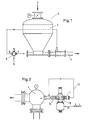
- FIG. 1 shows a system 1 for the pneumatic conveying of dust-like and / or fine-grained material to be conveyed with a delivery container 2.
- the delivery container 2 has a material inlet 3.
- a delivery line 4 is connected.
- a conveying gas supply 5 takes place to a valve 6.
- the valve 6 has a connection 7 for the conveying gas and, like a connection 8 for an additional gas supply.
- the connection 8 for the additional gas supply is connected directly to the delivery line 4.
- FIG. 2 shows the delivery line 4, to which an additional gas valve 9 is connected.
- the additional gas valve 9 is connected via the terminal 10 additional gas.
- a measuring line 12 is connected, which is directly connected to the delivery line 4 in connection.
- the connection 13 for conveying gas removal is likewise connected directly to the delivery line 4.
- FIG. 3 shows a valve 6 or 9 according to the invention. It has a conveying gas feed 5 or additional gas feed 8.
- the valve 6, 9 further has a connection 7, 11 for the conveying gas or for the measuring line 12.
- the valve 6, 9 has a connection 8, 13 for the additional gas or the additional gas discharge.
- the setting device 14 operates via a spring 15 on a membrane 16. On the opposite side of the spring 16 of the diaphragm acting at the terminal 7, 11 pressure from the delivery line 4 and measuring line 12 acts. If this pressure is less than the set spring pressure, so compressed gas from the port 5, 8 via the valve 6, 9 to the port 7, 11 passed. As the pressure at port 7, 11 becomes greater than the set spring force, diaphragm 16 shifts upward, as shown in FIG.
- a valve stem 17 is arranged on the membrane 16. This valve stem 17 closes by its movement on the one hand, the opening 18 shown in Figure 3 and on the other hand opens the opening 19 shown in Figure 4. Thus, compressed air from the port 5, 8 to the port 8, 13 arrive. The pressure gas present at a constant pressure at the connection 5, 8 is blown directly into the delivery line 4 from the connection 8, 13.
Landscapes
- Engineering & Computer Science (AREA)
- Mechanical Engineering (AREA)
- Air Transport Of Granular Materials (AREA)
- Paper (AREA)
- Crucibles And Fluidized-Bed Furnaces (AREA)
- Heat Treatments In General, Especially Conveying And Cooling (AREA)
Abstract
Description
- Anlage zum pneumatischen Fördern von staubförmigem und/oder feinkörnigem Fördergut
- Die Erfindung betrifft eine Anlage zum pneumatischen Fördern von staubförmigem und/oder feinkörnigem Fördergut mit einem Förderbehälter mit Materialzulauf, einer Förderleitung, einer Fördergaszufuhr, einer Zusatzgaszufuhr sowie einer Regelung für das Fördergas.
- Derartige Anlagen zum pneumatischen Fördern von staubförmigem Fördergut, seien es nun feine oder grobe oder auch gemischte Stäube bzw. feinkörniges Schüttgut, sind bekannt. Hier wird das staubförmige Fördergut durch ein Fördergas fluidisiert und in diesen Zustand mit dem Fördergas durch die Förderleitung transportiert. Es ist auch schon eine Regelung bzw. Steuerung zum Beeinflussen des pneumatischen Förderers bekannt. Die Regelung für das Fördergas erfolgt durch einen Druckaufnehmer in der Förderleitung, dessen elektrische Signale für die Beeinflussung der auf die Länge der Förderleitung an verschiedenen Stellen zugeführten Zusatzgases, eventuell die Materialzufuhr sowie die Fördergaszufuhr herangezogen werden. Beginnt sich nämlich eine Förderleitung mit Staub zuzusetzen, so erhöht sich der Druck in der Förderleitung. Die elektrischen Drucksignale werden dann zur Steuerung der Fördergaszufuhr sowie der Zusatzgaszufuhr und ggf. der Materialzufuhr verwendet. Droht die Förderleitung zu verstopfen, so wird die Fördergaszufuhr herunter geregelt, so dass weniger Material nachgefördert wird. Dafür wird die Zusatzgaszufuhr erhöht, damit eine größere Luftströmung erzeugt wird, die der Verstopfung entgegenwirkt.
- Diese Regelvorrichtung ist nicht nur wegen des Druckaufnehmers und der langen Signalleitung zur Übermittlung der Drucksignale aufwendig. Auch die Regeleinheit und ggf. das Programm für die Regeleinheit sind teuer und die ganze Anlage ist anfällig.
- Der Erfindung liegt daher die Aufgabe zugrunde, eine Anlage zum pneumatischen Fördern von staubförmigem und/oder feinkörnigem Fördergut so weiterzubilden, dass sie ohne aufwendige Drucksensoren und Signalleitungen sowie elektronische Regelungen auskommt, leicht, auch von ungelerntem Personal zu bedienen ist, und kostengünstig zu Erstellen und Betreiben ist.
- Zur Lösung der Aufgabe wird vorgeschlagen, dass die Regelung der Fördergasmenge und/oder der Zusatzgaszufuhrmenge im Bereich der Druckerfassung mechanisch erfolgt. Dadurch, dass die Regelung im Bereich der Druckerfassung erfolgt sind anfällige Signalleitungen überflüssig. Durch die mechanische Regelung kommt die Anlage zum pneumatischen Fördern von staubförmigem Fördergut ohne aufwändige elektronische Regelungen aus.
- Von Vorteil ist, dass für die Regelung der Fördergasmenge ein Ventil vorgesehen ist, dass das Ventil mindestens einen Anschluss für die Druckgaszufuhr, mindestens einen Anschluss für das Fördergas sowie mindestens einen Anschluss für das Zusatzgas aufweist, dass der Anschluss für das Fördergas über den Förderbehälter mit der Förderleitung in Verbindung steht und dass das Ventil in Abhängigkeit vom Druck am Anschluss für das Fördergas die Druckluftzufuhr auf die Anschlüsse für das Fördergas und die Anschlüsse für das Zusatzgas verteilt.
- Steigt der Druck am Anschluss für das Fördergas, z.B. einer Förderluft über ein dem Ventil vorgegebenen Druck hinaus, so wird die Druckluftzufuhr am Anschluss für die Förderluft reduziert und am Anschluss für die Zusatzluft erhöht. Steigt der Druck am Anschluss für die Förderluft weiter, so wird letztendlich die Druckluftzufuhr vom Anschluss für die Förderluft auf den Anschluss für die Zusatzluft umgeleitet, so dass kein weiteres Material mehr gefördert wird und über die Zusatzluft die Leitungen freigeblasen werden können.
- Dazu hat sich bewährt, dass der Anschluss für die Zusatzluft direkt mit der Förderleitung in Verbindung steht. Die Zusatzluft kann an mehreren Stellen in die Förderleitung eingespeist werden.
- Nachahmenswert ist, dass das Ventil eine Einrichtung zur Einstellung des maximalen Förderdrucks aufweist. Auch diese Einstellung erfolgt mechanisch. Wird der maximal eingestellte Förderdruck überstiegen, wird die Druckluftzufuhr nicht mehr über den Anschluss für die Förderluft in den Förderbehälter sondern über den Anschluss für die Zusatzluft direkt in die Förderleitung geblasen. Dieser Übergang kann, wie oben ausgeführt, fließend sein.
- Das Ventil ist so aufgebaut, dass bis zum Erreichen des maximalen Förderdrucks die Druckluftzufuhr mit dem Anschluss für die Förderluft verbunden ist und dass beim Übersteigen des eingestellten maximalen Förderdrucks die Druckluftzufuhr, ggf. fließend, mit dem Anschluss für die Zusatzluft verbunden wird.
- Es besteht auch die Möglichkeit, die Zusatzgaszufuhr direkt im Bereich des Anschlusses der Zusatzgaszufuhr an der Förderleitung mechanisch zu regeln. Dazu ist ein Zusatzgasventil vorgesehen, das einen Anschluss für das Zusatzgas aufweist. Weiterhin besitzt es einen Anschluss für eine Messleitung und einen Anschluss für die Zusatzgasabfuhr. Die Messleitung weist vorzugsweise gegenüber der Leitung für die Zusatzgasabfuhr einen kleinen Querschnitt auf. Sowohl der Anschluss für die Messleitung als auch der Anschluss für die Zusatzgasabfuhr sind direkt mit der Förderleitung verbunden. Das Zusatzgasventil verteilt in Abhängigkeit vom Druck in der Förderleitung, ermittelt am Anschluss der Messleitung, die Zusatzgaszufuhr zum Anschluss für die Messleitung und zum Anschluss für die Zusatzgasabfuhr. Damit wird erreicht, dass dann, wenn der Druck in der Messleitung über einen vorgegebenen Wert steigt, das Zusatzgas direkt über die Zusatzgasabfuhr in die Förderleitung geblasen werden kann. Auch hier kann der Übergang fließend sein.
- Von Vorteil ist dabei, dass das Zusatzgasventil eine Einrichtung zur Einstellung des maximalen Förderdrucks aufweist und dass bis zum Erreichen des maximalen Förderdrucks die Zusatzgaszufuhr mit dem Anschluss der Messleitung verbunden ist und dass beim Überschreiten des maximalen Förderdrucks die Zusatzgaszufuhr mit dem Anschluss für die Zusatzgasabfuhr verbunden ist. Auch dieses Zusatzgasventil gewährleistet, dass keine elektrischen Druckaufnehmer und elektrischen Steuerungen notwendig sind, um die Förderleitung ggf. freiblasen zu können.
- Es hat sich bewährt, dass die Ventile eine Membran aufweisen, die einerseits durch eine Feder und andererseits durch den an dem Anschluss für die Förderluft bzw. durch den an dem Messanschluss herrschenden Druck der Förderleitung beaufschlagt ist, und dass die Druckmembran mit einem doppelt wirkenden Ventilschaft verbunden ist.
- Übersteigt der Druck am Anschluss für die Förderluft bzw. am Messanschluss die Kraft der Feder, so bewegt sich die Membran. Mit dieser Membran bewegt sich ein Ventilschaft, der den Weg von der Druckluftzufuhr zum Anschluss für die Förderluft bzw. zur Messleitung absperrt und dafür den Weg zum Anschluss für die Zusatzluft bzw. zum Anschluss für die Zusatzabluft freigibt.
- Von Vorteil ist, dass die Feder in ihrer Federkraft mechanisch einstellbar ist. Hier kann durch ein einfaches ggf. skaliertes Wählrad die Federkraft und damit der maximale Druck eingestellt werden, bei dem eine, ggf. schleichende, Umschaltung von dem Einblasen in den Förderbehälter zum direkten Einblasen und Reinigen der Förderleitung erfolgt.
-
- Figur 1
- eine erfindungsgemäße Anlage zum Fördern von staubförmigem und/oder feinkörnigem Fördergut,
- Figur 2
- eine Anbindung eines Zusatzgasventils an die Förderleitung,
- Figur 3
- ein erfindungsgemäßes Ventil, bei dem die Druckluftzufuhr über das Ventil zum Anschluss für die Förderluft erfolgt und
- Figur 4
- ein erfindungsgemäßes Ventil, bei dem die Druckluftzufuhr über das Ventil zum Anschluss für die Zusatzluft erfolgt.
- Figur 1 zeigt eine Anlage 1 zum pneumatischen Fördern von staubförmigem und/oder feinkörnigem Fördergut mit einem Förderbehälter 2. Der Förderbehälter 2 weist einen Materialzulauf 3 auf. Am Förderbehälter 2 ist eine Förderleitung 4 angeschlossen. Eine Fördergaszufuhr 5 erfolgt zu einem Ventil 6. Das Ventil 6 weist einen Anschluss 7 für das Fördergas sowie wie einen Anschluss 8 für eine Zusatzgaszufuhr auf. Der Anschluss 8 für die Zusatzgaszufuhr ist direkt mit der Förderleitung 4 verbunden.
- Figur 2 zeigt die Förderleitung 4, an die ein Zusatzgasventil 9 angeschlossen ist. Dem Zusatzgasventil 9 wird über den Anschluss 10 Zusatzgas aufgeschaltet. Am Anschluss 11 ist eine Messleitung 12 angeschlossen, die direkt mit der Förderleitung 4 in Verbindung steht. Der Anschluss 13 für die Fördergasabfuhr ist ebenfalls direkt mit der Förderleitung 4 verbunden.
- Figur 3 zeigt ein erfindungsgemäßes Ventil 6 bzw. 9. Es weist eine Fördergaszufuhr 5 bzw. Zusatzgaszufuhr 8 auf. Das Ventil 6, 9 besitzt weiterhin einen Anschluss 7, 11 für das Fördergas bzw. für die Messleitung 12. Zudem weist das Ventil 6, 9 einen Anschluss 8, 13 für das Zusatzgas bzw. die Zusatzgasabfuhr auf. Über eine Einstellvorrichtung 14 lässt sich der maximale Förderdruck einstellen. Die Einstellvorrichtung 14 arbeitet über eine Feder 15 auf eine Membran 16. Auf die der Feder entgegengesetzten Seite der Membran 16 wirkt der am Anschluss 7, 11 anstehende Druck aus der Förderleitung 4 bzw. Messleitung 12. Ist dieser Druck kleiner als der eingestellte Federdruck, so wird Druckgas vom Anschluss 5, 8 über das Ventil 6, 9 zum Anschluss 7, 11 geleitet. Sowie der Druck am Anschluss 7, 11 größer wird als die eingestellte Federkraft, verschiebt sich die Membran 16 nach oben, wie dies Figur 4 zeigt.
- Wie Figur 4 zu entnehmen ist, ist an der Membran 16 ein Ventilschaft 17 angeordnet. Dieser Ventilschaft 17 schließt durch seine Bewegung einerseits die in Figur 3 dargestellte Öffnung 18 und öffnet andererseits die in Figur 4 dargestellte Öffnung 19. Damit kann Druckluft vom Anschluss 5, 8 zum Anschluss 8, 13 gelangen. Das mit einem konstanten Druck am Anschluss 5, 8 anstehende Druckgas wird vom Anschluss 8, 13 direkt in die Förderleitung 4 geblasen.
- Bezugszeichenübersicht
- 1. Anlage
- 2. Förderbehälter
- 3. Materialzulauf
- 4. Förderleitung
- 5. Fördergaszufuhr
- 6. Ventil
- 7. Anschluss für Fördergas
- 8. Anschluss Zusatzgas
- 9. Zusatzgasventil
- 10. Anschluss Zusatzgaszufuhr 11.Anschluss Messleitung
- 12. Messleitung
- 13. Anschluss Zusatzgasabfuhr
- 14. Einstellvorrichtung
- 15. Feder
- 16. Membran
- 17. Ventilschaft
- 18. Öffnung
- 19. Öffnung
Claims (11)
- Anlage (1) zum pneumatischen Fördern von staubförmigem und/oder feinkörnigem Fördergut mit einem Förderbehälter (2) mit Materialzulauf (3), einer Förderleitung (4), einer Fördergaszufuhr (5), einer Zusatzgaszufuhr sowie einer Regelung für das Fördergas,
dadurch gekennzeichnet,
dass die Regelung der Fördergasmenge und/oder der Zusatzgaszufuhrmenge im Bereich der Druckerfassung mechanisch erfolgt. - Anlage nach Anspruch 1,
dadurch gekennzeichnet,
dass für die Regelung der Fördergasmenge ein Ventil (6) vorgesehen ist, dass das Ventil (6) mindestens einen Anschluss für die Fördergaszufuhr (5), mindestens einen Anschluss (7) zur Abgabe des Fördergases sowie mindestens einen Anschluss (8) für das Zusatzgas aufweist, dass der Anschluss (7) über den Förderbehälter (2) mit der Förderleitung (4) in Verbindung steht und dass das Ventil (6) in Abhängigkeit vom Druck am Anschluss (7) für das Fördergas die Fördergaszufuhr zwischen dem Anschluss (7) für das Fördergas und dem Anschluss (8) für das Zusatzgas verteilt. - Anlage nach Anspruch 2.
dadurch gekennzeichnet,
dass der Anschluss (8) für das Zusatzgas direkt mit der Förderleitung (4) in Verbindung steht. - Anlage nach Anspruch 2 oder 3,
dadurch gekennzeichnet,
dass das Ventil (6) eine Vorrichtung (14) zur Einstellung des maximalen Förderdrucks aufweist. - Anlage nach Anspruch 4,
dadurch gekennzeichnet,
dass bis zum Erreichen des maximalen Förderdrucks die Druckgaszufuhr mit dem Anschluss (7) für das Fördergas verbunden ist und dass beim Überschreiten des maximalen Förderdrucks die Druckgaszufuhr mit dem Anschluss (8) für das Zusatzgasverbunden ist. - Anlage nach Anspruch 1,
dadurch gekennzeichnet,
dass für die Regelung der Zusatzgaszufuhr ein Zusatzgasventil (9) vorgesehen ist, dass das Zusatzgasventil (9) einen Anschluss (10) für das Zusatzgas, einen Anschluss (11) für eine Messleitung (12) und einen Anschluss (13) für die Zusatzgasabfuhr aufweist, dass der Anschluss (13) für die Messleitung (12) und der Anschluss (13) für die Zusatzgasabfuhr direkt mit der Förderleitung (4) verbunden sind und dass das Zusatzgasventil (9) in Abhängigkeit vom Druck in der Förderleitung (4) das Zusatzgas auf den Anschluss (11) für die Messleitung (12) und den Anschluss (13) für die Zusatzgasabfuhr verteilt. - Anlagen nach Anspruch 6,
dadurch gekennzeichnet,
dass der Querschnitt der Messleitung gegenüber dem Querschnitt der Leitung für die Zusatzgasabfuhr klein ist. - Anlagen nach Anspruch 6 oder 7,
dadurch gekennzeichnet,
dass das Ventil (9) eine Vorrichtung (14) zur Einstellung des maximalen Förderdrucks aufweist. - Anlage nach Anspruch 8,
dadurch gekennzeichnet,
dass bis zum Erreichen des maximalen Förderdrucks die Druckgaszufuhr mit dem Anschluss (11) für die Messleitung (12) verbunden ist und dass beim Überschreiten des maximalen Förderdrucks die Zusatzgaszufuhr mit dem Anschluss (13) für die Zusatzgasabfuhr verbunden ist. - Anlage nach einem der Ansprüche 1 bis 9,
dadurch gekennzeichnet, dass die Ventile (6, 9) eine Membran (16) aufweisen, die einerseits durch eine Feder (15) und andererseits durch den am Anschluss (7, 11) für das Fördergas bzw. am Anschluss der Messleitung (12) herrschenden Druck der Förderleitung (4) beaufschlagt ist und dass die Membran (16) mit einem doppelt wirkenden Ventilschaft (17) verbunden ist. - Anlage nach Anspruch 10,
dadurch gekennzeichnet,
dass die Feder (15) in ihrer Federkraft einstellbar ist.
Priority Applications (3)
| Application Number | Priority Date | Filing Date | Title |
|---|---|---|---|
| AT05007926T ATE401276T1 (de) | 2005-04-12 | 2005-04-12 | Anlage zum pneumatischen fördern von staubförmigem und/oder feinkörnigem fördergut |
| EP05007926A EP1712497B1 (de) | 2005-04-12 | 2005-04-12 | Anlage zum pneumatischen Fördern von staubförmigem und/oder feinkörnigem Fördergut |
| DE502005004728T DE502005004728D1 (de) | 2005-04-12 | 2005-04-12 | Anlage zum pneumatischen Fördern von staubförmigem und/oder feinkörnigem Fördergut |
Applications Claiming Priority (1)
| Application Number | Priority Date | Filing Date | Title |
|---|---|---|---|
| EP05007926A EP1712497B1 (de) | 2005-04-12 | 2005-04-12 | Anlage zum pneumatischen Fördern von staubförmigem und/oder feinkörnigem Fördergut |
Publications (2)
| Publication Number | Publication Date |
|---|---|
| EP1712497A1 true EP1712497A1 (de) | 2006-10-18 |
| EP1712497B1 EP1712497B1 (de) | 2008-07-16 |
Family
ID=34935005
Family Applications (1)
| Application Number | Title | Priority Date | Filing Date |
|---|---|---|---|
| EP05007926A Expired - Lifetime EP1712497B1 (de) | 2005-04-12 | 2005-04-12 | Anlage zum pneumatischen Fördern von staubförmigem und/oder feinkörnigem Fördergut |
Country Status (3)
| Country | Link |
|---|---|
| EP (1) | EP1712497B1 (de) |
| AT (1) | ATE401276T1 (de) |
| DE (1) | DE502005004728D1 (de) |
Cited By (2)
| Publication number | Priority date | Publication date | Assignee | Title |
|---|---|---|---|---|
| CN110271868A (zh) * | 2018-03-13 | 2019-09-24 | 红塔烟草(集团)有限责任公司 | 一种固体物料输送的截止装置 |
| CN115849012A (zh) * | 2022-11-18 | 2023-03-28 | 中冶南方(湖南)工程技术有限公司 | 焦粉气力输送方法及系统 |
Citations (2)
| Publication number | Priority date | Publication date | Assignee | Title |
|---|---|---|---|---|
| GB1360424A (en) * | 1971-09-03 | 1974-07-17 | Ind Pneumatic Systems Inc | Conveying of fluidized material |
| DE3042201A1 (de) * | 1980-11-08 | 1982-06-16 | Schaad, Hans-Julius, 4600 Dortmund | Verfahren zum pneumatischen foerdern und dosieren fuerpulverfoermige, in einem treibgasstrom mitgefuehrte pulverpartikel und einrichtung zur durchfuehrung des verfahrens |
-
2005
- 2005-04-12 AT AT05007926T patent/ATE401276T1/de not_active IP Right Cessation
- 2005-04-12 DE DE502005004728T patent/DE502005004728D1/de not_active Expired - Lifetime
- 2005-04-12 EP EP05007926A patent/EP1712497B1/de not_active Expired - Lifetime
Patent Citations (2)
| Publication number | Priority date | Publication date | Assignee | Title |
|---|---|---|---|---|
| GB1360424A (en) * | 1971-09-03 | 1974-07-17 | Ind Pneumatic Systems Inc | Conveying of fluidized material |
| DE3042201A1 (de) * | 1980-11-08 | 1982-06-16 | Schaad, Hans-Julius, 4600 Dortmund | Verfahren zum pneumatischen foerdern und dosieren fuerpulverfoermige, in einem treibgasstrom mitgefuehrte pulverpartikel und einrichtung zur durchfuehrung des verfahrens |
Cited By (2)
| Publication number | Priority date | Publication date | Assignee | Title |
|---|---|---|---|---|
| CN110271868A (zh) * | 2018-03-13 | 2019-09-24 | 红塔烟草(集团)有限责任公司 | 一种固体物料输送的截止装置 |
| CN115849012A (zh) * | 2022-11-18 | 2023-03-28 | 中冶南方(湖南)工程技术有限公司 | 焦粉气力输送方法及系统 |
Also Published As
| Publication number | Publication date |
|---|---|
| DE502005004728D1 (de) | 2008-08-28 |
| EP1712497B1 (de) | 2008-07-16 |
| ATE401276T1 (de) | 2008-08-15 |
Similar Documents
| Publication | Publication Date | Title |
|---|---|---|
| DE69804959T2 (de) | Verfahren und vorrichtung zum transport von schüttgut, körnigem material oder pulverförmigem material | |
| DE10039564A1 (de) | Vorrichtung zum Fördern von Schüttgut | |
| DE3529144C2 (de) | ||
| DE3225449C2 (de) | Verfahren und Vorrichtung zum Messen und/oder Regeln des Massestromes von Feststoffteilchen | |
| DE2855751A1 (de) | Einrichtung zum pneumatischen beschicken einer behaelterwaage | |
| EP0603601B1 (de) | Vorrichtung zum pneumatischen Fördern von Schüttgut | |
| DE811578C (de) | Pneumatische Foerderanlage mit mehreren an ein gemeinsames Geblaese angeschlossenen Foerderrohren, insbesondere fuer Muehlen mit mehreren Passagen | |
| DE3323739C2 (de) | Vorrichtung zur Pfropfenförderung von Schüttgut | |
| EP1712497B1 (de) | Anlage zum pneumatischen Fördern von staubförmigem und/oder feinkörnigem Fördergut | |
| DE4109960A1 (de) | Verfahren und anlage zur pneumatischen saugfoerderung von schuettgut | |
| DE3109111A1 (de) | "anlage zum eingeben von kohle in metallurgische prozessgefaesse mit einer vielzahl von einblasstellen und verfahren zum betreiben der anlage" | |
| EP1129019B1 (de) | Verfahren und vorrichtung zur pneumatischen förderung von schüttgut | |
| DE102013101385A1 (de) | Pelletstaubabsaugung | |
| DE2363505A1 (de) | Aufgabevorrichtung einer druckluftfoerderanlage fuer schuettgut | |
| EP0417444A2 (de) | Vorrichtung zum Ausschleusen von feinkörnigen Feststoffen | |
| DE102012014866B4 (de) | Steuereinheit für Ventile zur gleichzeitigen Vor- und Minderdruckregelung in Dampferzeugern | |
| EP3691950B1 (de) | Strömungseinrichtung und verfahren zum steuern und/oder einstellen eines gegendrucks in einer pneumatischen sandfördervorrichtung für ein schienenfahrzeug und sandfördervorrichtung mit einer strömungseinrichtung | |
| DE2618541A1 (de) | Filterabscheider fuer eine pneumatische foerderanlage | |
| DE3407402A1 (de) | Pneumatisches foerderverfahren fuer fliessfaehige schuettgueter | |
| DE3024743C2 (de) | Regelvorrichtung für eine pneumatische Förderanlage | |
| DE3219813C2 (de) | Vorrichtung zum Fördern pulverförmiger Stoffe von einem unter Druck stehenden Behälter zu einer Abgabestelle | |
| DE926417C (de) | Vorrichtung zur Entnahme von Schuettgut aus einem Vorratsbunker | |
| DE1809067B2 (de) | Anlage, insbesondere zum Kühlen von Schüttgut | |
| DE2906206C2 (de) | Anordnung und Ausbildung eines Sichters in einer Saugluftförderanlage | |
| DE320568C (de) | Sichtvorrichtung zum Entstauben oder zum Klassieren von trocknem Gute, wie Kohle, Mineralien, Korn u. dgl. |
Legal Events
| Date | Code | Title | Description |
|---|---|---|---|
| PUAI | Public reference made under article 153(3) epc to a published international application that has entered the european phase |
Free format text: ORIGINAL CODE: 0009012 |
|
| AK | Designated contracting states |
Kind code of ref document: A1 Designated state(s): AT BE BG CH CY CZ DE DK EE ES FI FR GB GR HU IE IS IT LI LT LU MC NL PL PT RO SE SI SK TR |
|
| AX | Request for extension of the european patent |
Extension state: AL BA HR LV MK YU |
|
| 17P | Request for examination filed |
Effective date: 20070410 |
|
| AKX | Designation fees paid |
Designated state(s): AT BE BG CH CY CZ DE DK EE ES FI FR GB GR HU IE IS IT LI LT LU MC NL PL PT RO SE SI SK TR |
|
| 17Q | First examination report despatched |
Effective date: 20070605 |
|
| GRAP | Despatch of communication of intention to grant a patent |
Free format text: ORIGINAL CODE: EPIDOSNIGR1 |
|
| GRAS | Grant fee paid |
Free format text: ORIGINAL CODE: EPIDOSNIGR3 |
|
| GRAA | (expected) grant |
Free format text: ORIGINAL CODE: 0009210 |
|
| AK | Designated contracting states |
Kind code of ref document: B1 Designated state(s): AT BE BG CH CY CZ DE DK EE ES FI FR GB GR HU IE IS IT LI LT LU MC NL PL PT RO SE SI SK TR |
|
| REG | Reference to a national code |
Ref country code: GB Ref legal event code: FG4D Free format text: NOT ENGLISH |
|
| REG | Reference to a national code |
Ref country code: CH Ref legal event code: EP |
|
| REF | Corresponds to: |
Ref document number: 502005004728 Country of ref document: DE Date of ref document: 20080828 Kind code of ref document: P |
|
| REG | Reference to a national code |
Ref country code: IE Ref legal event code: FG4D Free format text: LANGUAGE OF EP DOCUMENT: GERMAN |
|
| NLV1 | Nl: lapsed or annulled due to failure to fulfill the requirements of art. 29p and 29m of the patents act | ||
| PG25 | Lapsed in a contracting state [announced via postgrant information from national office to epo] |
Ref country code: PT Free format text: LAPSE BECAUSE OF FAILURE TO SUBMIT A TRANSLATION OF THE DESCRIPTION OR TO PAY THE FEE WITHIN THE PRESCRIBED TIME-LIMIT Effective date: 20081216 Ref country code: NL Free format text: LAPSE BECAUSE OF FAILURE TO SUBMIT A TRANSLATION OF THE DESCRIPTION OR TO PAY THE FEE WITHIN THE PRESCRIBED TIME-LIMIT Effective date: 20080716 Ref country code: LT Free format text: LAPSE BECAUSE OF FAILURE TO SUBMIT A TRANSLATION OF THE DESCRIPTION OR TO PAY THE FEE WITHIN THE PRESCRIBED TIME-LIMIT Effective date: 20080716 Ref country code: IS Free format text: LAPSE BECAUSE OF FAILURE TO SUBMIT A TRANSLATION OF THE DESCRIPTION OR TO PAY THE FEE WITHIN THE PRESCRIBED TIME-LIMIT Effective date: 20081116 Ref country code: ES Free format text: LAPSE BECAUSE OF FAILURE TO SUBMIT A TRANSLATION OF THE DESCRIPTION OR TO PAY THE FEE WITHIN THE PRESCRIBED TIME-LIMIT Effective date: 20081027 |
|
| PG25 | Lapsed in a contracting state [announced via postgrant information from national office to epo] |
Ref country code: FI Free format text: LAPSE BECAUSE OF FAILURE TO SUBMIT A TRANSLATION OF THE DESCRIPTION OR TO PAY THE FEE WITHIN THE PRESCRIBED TIME-LIMIT Effective date: 20080716 Ref country code: BG Free format text: LAPSE BECAUSE OF FAILURE TO SUBMIT A TRANSLATION OF THE DESCRIPTION OR TO PAY THE FEE WITHIN THE PRESCRIBED TIME-LIMIT Effective date: 20081016 Ref country code: SI Free format text: LAPSE BECAUSE OF FAILURE TO SUBMIT A TRANSLATION OF THE DESCRIPTION OR TO PAY THE FEE WITHIN THE PRESCRIBED TIME-LIMIT Effective date: 20080716 |
|
| REG | Reference to a national code |
Ref country code: IE Ref legal event code: FD4D |
|
| PG25 | Lapsed in a contracting state [announced via postgrant information from national office to epo] |
Ref country code: IE Free format text: LAPSE BECAUSE OF FAILURE TO SUBMIT A TRANSLATION OF THE DESCRIPTION OR TO PAY THE FEE WITHIN THE PRESCRIBED TIME-LIMIT Effective date: 20080716 Ref country code: DK Free format text: LAPSE BECAUSE OF FAILURE TO SUBMIT A TRANSLATION OF THE DESCRIPTION OR TO PAY THE FEE WITHIN THE PRESCRIBED TIME-LIMIT Effective date: 20080716 Ref country code: EE Free format text: LAPSE BECAUSE OF FAILURE TO SUBMIT A TRANSLATION OF THE DESCRIPTION OR TO PAY THE FEE WITHIN THE PRESCRIBED TIME-LIMIT Effective date: 20080716 |
|
| PLBE | No opposition filed within time limit |
Free format text: ORIGINAL CODE: 0009261 |
|
| STAA | Information on the status of an ep patent application or granted ep patent |
Free format text: STATUS: NO OPPOSITION FILED WITHIN TIME LIMIT |
|
| PG25 | Lapsed in a contracting state [announced via postgrant information from national office to epo] |
Ref country code: CZ Free format text: LAPSE BECAUSE OF FAILURE TO SUBMIT A TRANSLATION OF THE DESCRIPTION OR TO PAY THE FEE WITHIN THE PRESCRIBED TIME-LIMIT Effective date: 20080716 Ref country code: SK Free format text: LAPSE BECAUSE OF FAILURE TO SUBMIT A TRANSLATION OF THE DESCRIPTION OR TO PAY THE FEE WITHIN THE PRESCRIBED TIME-LIMIT Effective date: 20080716 Ref country code: RO Free format text: LAPSE BECAUSE OF FAILURE TO SUBMIT A TRANSLATION OF THE DESCRIPTION OR TO PAY THE FEE WITHIN THE PRESCRIBED TIME-LIMIT Effective date: 20080716 |
|
| 26N | No opposition filed |
Effective date: 20090417 |
|
| PG25 | Lapsed in a contracting state [announced via postgrant information from national office to epo] |
Ref country code: IT Free format text: LAPSE BECAUSE OF FAILURE TO SUBMIT A TRANSLATION OF THE DESCRIPTION OR TO PAY THE FEE WITHIN THE PRESCRIBED TIME-LIMIT Effective date: 20080716 |
|
| BERE | Be: lapsed |
Owner name: FORDER- UND ANLAGENTECHNIK G.M.B.H. Effective date: 20090430 |
|
| REG | Reference to a national code |
Ref country code: CH Ref legal event code: PL |
|
| GBPC | Gb: european patent ceased through non-payment of renewal fee |
Effective date: 20090412 |
|
| REG | Reference to a national code |
Ref country code: FR Ref legal event code: ST Effective date: 20091231 |
|
| PG25 | Lapsed in a contracting state [announced via postgrant information from national office to epo] |
Ref country code: CH Free format text: LAPSE BECAUSE OF NON-PAYMENT OF DUE FEES Effective date: 20090430 Ref country code: LI Free format text: LAPSE BECAUSE OF NON-PAYMENT OF DUE FEES Effective date: 20090430 Ref country code: SE Free format text: LAPSE BECAUSE OF FAILURE TO SUBMIT A TRANSLATION OF THE DESCRIPTION OR TO PAY THE FEE WITHIN THE PRESCRIBED TIME-LIMIT Effective date: 20081016 |
|
| PG25 | Lapsed in a contracting state [announced via postgrant information from national office to epo] |
Ref country code: MC Free format text: LAPSE BECAUSE OF NON-PAYMENT OF DUE FEES Effective date: 20090430 Ref country code: FR Free format text: LAPSE BECAUSE OF NON-PAYMENT OF DUE FEES Effective date: 20091222 Ref country code: GB Free format text: LAPSE BECAUSE OF NON-PAYMENT OF DUE FEES Effective date: 20090412 |
|
| PG25 | Lapsed in a contracting state [announced via postgrant information from national office to epo] |
Ref country code: BE Free format text: LAPSE BECAUSE OF NON-PAYMENT OF DUE FEES Effective date: 20090430 Ref country code: PL Free format text: LAPSE BECAUSE OF FAILURE TO SUBMIT A TRANSLATION OF THE DESCRIPTION OR TO PAY THE FEE WITHIN THE PRESCRIBED TIME-LIMIT Effective date: 20080716 |
|
| PG25 | Lapsed in a contracting state [announced via postgrant information from national office to epo] |
Ref country code: AT Free format text: LAPSE BECAUSE OF NON-PAYMENT OF DUE FEES Effective date: 20090412 |
|
| PG25 | Lapsed in a contracting state [announced via postgrant information from national office to epo] |
Ref country code: GR Free format text: LAPSE BECAUSE OF FAILURE TO SUBMIT A TRANSLATION OF THE DESCRIPTION OR TO PAY THE FEE WITHIN THE PRESCRIBED TIME-LIMIT Effective date: 20081017 |
|
| PG25 | Lapsed in a contracting state [announced via postgrant information from national office to epo] |
Ref country code: LU Free format text: LAPSE BECAUSE OF NON-PAYMENT OF DUE FEES Effective date: 20090412 |
|
| PG25 | Lapsed in a contracting state [announced via postgrant information from national office to epo] |
Ref country code: HU Free format text: LAPSE BECAUSE OF FAILURE TO SUBMIT A TRANSLATION OF THE DESCRIPTION OR TO PAY THE FEE WITHIN THE PRESCRIBED TIME-LIMIT Effective date: 20090117 |
|
| PGFP | Annual fee paid to national office [announced via postgrant information from national office to epo] |
Ref country code: DE Payment date: 20110421 Year of fee payment: 7 |
|
| PG25 | Lapsed in a contracting state [announced via postgrant information from national office to epo] |
Ref country code: TR Free format text: LAPSE BECAUSE OF FAILURE TO SUBMIT A TRANSLATION OF THE DESCRIPTION OR TO PAY THE FEE WITHIN THE PRESCRIBED TIME-LIMIT Effective date: 20080716 |
|
| PG25 | Lapsed in a contracting state [announced via postgrant information from national office to epo] |
Ref country code: CY Free format text: LAPSE BECAUSE OF FAILURE TO SUBMIT A TRANSLATION OF THE DESCRIPTION OR TO PAY THE FEE WITHIN THE PRESCRIBED TIME-LIMIT Effective date: 20080716 |
|
| REG | Reference to a national code |
Ref country code: DE Ref legal event code: R119 Ref document number: 502005004728 Country of ref document: DE Effective date: 20121101 |
|
| PG25 | Lapsed in a contracting state [announced via postgrant information from national office to epo] |
Ref country code: DE Free format text: LAPSE BECAUSE OF NON-PAYMENT OF DUE FEES Effective date: 20121101 |