EP1712686A2 - Elément de connection, en particulier pour treillis d'armature - Google Patents
Elément de connection, en particulier pour treillis d'armature Download PDFInfo
- Publication number
- EP1712686A2 EP1712686A2 EP06007242A EP06007242A EP1712686A2 EP 1712686 A2 EP1712686 A2 EP 1712686A2 EP 06007242 A EP06007242 A EP 06007242A EP 06007242 A EP06007242 A EP 06007242A EP 1712686 A2 EP1712686 A2 EP 1712686A2
- Authority
- EP
- European Patent Office
- Prior art keywords
- connecting element
- element according
- sections
- wire mesh
- wire
- Prior art date
- Legal status (The legal status is an assumption and is not a legal conclusion. Google has not performed a legal analysis and makes no representation as to the accuracy of the status listed.)
- Granted
Links
Images
Classifications
-
- F—MECHANICAL ENGINEERING; LIGHTING; HEATING; WEAPONS; BLASTING
- F16—ENGINEERING ELEMENTS AND UNITS; GENERAL MEASURES FOR PRODUCING AND MAINTAINING EFFECTIVE FUNCTIONING OF MACHINES OR INSTALLATIONS; THERMAL INSULATION IN GENERAL
- F16B—DEVICES FOR FASTENING OR SECURING CONSTRUCTIONAL ELEMENTS OR MACHINE PARTS TOGETHER, e.g. NAILS, BOLTS, CIRCLIPS, CLAMPS, CLIPS OR WEDGES; JOINTS OR JOINTING
- F16B12/00—Jointing of furniture or the like, e.g. hidden from exterior
- F16B12/10—Jointing of furniture or the like, e.g. hidden from exterior using pegs, bolts, tenons, clamps, clips, or the like
- F16B12/28—Jointing of furniture or the like, e.g. hidden from exterior using pegs, bolts, tenons, clamps, clips, or the like for metal furniture parts
- F16B12/32—Jointing of furniture or the like, e.g. hidden from exterior using pegs, bolts, tenons, clamps, clips, or the like for metal furniture parts using clamps, clips, wedges, sliding bolts, or the like
-
- A—HUMAN NECESSITIES
- A47—FURNITURE; DOMESTIC ARTICLES OR APPLIANCES; COFFEE MILLS; SPICE MILLS; SUCTION CLEANERS IN GENERAL
- A47B—TABLES; DESKS; OFFICE FURNITURE; CABINETS; DRAWERS; GENERAL DETAILS OF FURNITURE
- A47B55/00—Cabinets, racks or shelf units, having essential features of rigid construction
- A47B55/02—Cabinets, racks or shelf units, having essential features of rigid construction made of wire
-
- E—FIXED CONSTRUCTIONS
- E02—HYDRAULIC ENGINEERING; FOUNDATIONS; SOIL SHIFTING
- E02D—FOUNDATIONS; EXCAVATIONS; EMBANKMENTS; UNDERGROUND OR UNDERWATER STRUCTURES
- E02D29/00—Independent underground or underwater structures; Retaining walls
- E02D29/02—Retaining or protecting walls
- E02D29/0208—Gabions
-
- E—FIXED CONSTRUCTIONS
- E04—BUILDING
- E04C—STRUCTURAL ELEMENTS; BUILDING MATERIALS
- E04C5/00—Reinforcing elements, e.g. for concrete; Auxiliary elements therefor
- E04C5/01—Reinforcing elements of metal, e.g. with non-structural coatings
- E04C5/02—Reinforcing elements of metal, e.g. with non-structural coatings of low bending resistance, i.e. of essentially one-dimensional [1D] or two-dimensional [2D] extent
- E04C5/04—Mats
-
- E—FIXED CONSTRUCTIONS
- E04—BUILDING
- E04C—STRUCTURAL ELEMENTS; BUILDING MATERIALS
- E04C5/00—Reinforcing elements, e.g. for concrete; Auxiliary elements therefor
- E04C5/16—Auxiliary parts for reinforcements, e.g. connectors, spacers, stirrups
- E04C5/162—Connectors or means for connecting parts for reinforcements
- E04C5/163—Connectors or means for connecting parts for reinforcements the reinforcements running in one single direction
-
- F—MECHANICAL ENGINEERING; LIGHTING; HEATING; WEAPONS; BLASTING
- F16—ENGINEERING ELEMENTS AND UNITS; GENERAL MEASURES FOR PRODUCING AND MAINTAINING EFFECTIVE FUNCTIONING OF MACHINES OR INSTALLATIONS; THERMAL INSULATION IN GENERAL
- F16B—DEVICES FOR FASTENING OR SECURING CONSTRUCTIONAL ELEMENTS OR MACHINE PARTS TOGETHER, e.g. NAILS, BOLTS, CIRCLIPS, CLAMPS, CLIPS OR WEDGES; JOINTS OR JOINTING
- F16B2/00—Friction-grip releasable fastenings
- F16B2/20—Clips, i.e. with gripping action effected solely by the inherent resistance to deformation of the material of the fastening
- F16B2/26—Clips, i.e. with gripping action effected solely by the inherent resistance to deformation of the material of the fastening of pliable, non-resilient material, e.g. plant tie
Definitions
- the invention relates to a connecting element, preferably for wire mesh, according to the preamble of claim 1.
- wire baskets from wire meshes.
- the wire mesh are connected to each other with fasteners in the form of closing, hooks, eyes and the like. Eyelets as fasteners are initially open and are bent after hanging in the wire mesh with tools and optionally welded. A loosening of the wire mesh is possible only with destruction of the eyelets.
- the invention has the object of providing the generic connection element in such a way that it is easy to assemble and securely holds together the interconnected parts.
- the connecting element according to the invention can be easily mounted because it is open.
- the connecting element is placed on the parts to be joined so that they into the insertion opening between the limb body portions can reach. They are offset from one another and have a distance from each other which corresponds approximately to the thickness of the part to be hooked.
- the connecting element Since the insertion opens into the suspension opening, the connecting element is moved so that the Detectiveierde part of the insertion enters the suspension opening. Then, the connecting element according to the invention can be rotated so that the parts to be hooked get into the suspension opening. Since the link body portions are arranged offset from one another, the connecting member must be rotated after placement on the parts to be hooked, so that they pass from the insertion into the suspension opening. Thus, the connecting element can be easily put on. When mounted, it sits securely on the interconnected parts. In normal use, the connecting element is no longer in the position that it needs to hang. Since the connecting element is open even in the mounted position, it can be removed at any time without special tools if necessary.
- the sections limit the suspension opening.
- At least one of the sections is provided with at least one locking part. It is advantageous if both sections have at least one locking part. It serves as an additional safeguard that the hinged part can not get out of the suspension hole in the insertion during relative movements between it and the connecting element.
- the locking part seen in side view of the connecting element, protrudes into its suspension opening.
- This locking part provides an additional safeguard against unintentional unhooking. Should the hinged part reach the area of the base body sections, the blocking parts prevent the parts to be hooked from entering the insertion opening.
- the locking member is advantageously at an obtuse angle to the body portion, whereby an additional security against unintentional unhooking is achieved.
- the blocking part is formed integrally with the main body portion.
- the blocking part can be produced for example by a turn of the body portion.
- connecting element in one piece as a whole. It can then be made very simple and inexpensive, for example, by a wire section.
- the body portions preferably connect to arc portions. As a result, the parts suspended in the connecting element can easily perform any required relative movements to the connecting element.
- the bow sections advantageously connect the body portions to an opposing body portion.
- the arcuate portions are preferably in acute angles to each other lying planes, so that the connecting element has a restricted shape. Because of this design, the overlapping body portions can be easily manufactured.
- the arc sections and the associated base body sections each lie in a plane.
- the arc sections with the adjoining basic body sections and the blocking parts are thus in the planes lying at an acute angle to one another.
- the connecting element therefore has a front view V-shape.
- the hinged parts in the connecting element in spite of the locking parts still have plenty of opportunities for movement, the locking parts end at a distance from the bow sections.
- the body portions are at the same height.
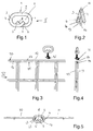
- the connecting element has a main body 1, which is designed as an open ring.
- the main body has a straight section 2, which merges into semi-circular arc sections 3, 4 at both ends.
- the arcuate section 3 merges into a straight leg section 5 lying parallel to the section 2, the free end 6 of which runs at an obtuse angle in the direction of the main body section 2.
- the arcuate portion 4 also merges into a straight leg portion 7 lying parallel to the portion 2, the free end 8 of which runs at an obtuse angle in the direction of the opposite base body portion 2.
- the straight, equal length and at the same height adjacent leg portions 5 and 7 extend to about half the length of the connecting element, seen in side view of FIG. 1.
- the angled ends 6, 8 are approximately at right angles to each other and protrude, seen in side view, in the insertion opening 9 of the connecting element.
- the distance between the free ends 6, 8 and the opposite base body portion 2 is greater than the projection of the free ends 6, 8 via their leg portions 5, 7, which define an insertion opening 16. It opens into the suspension opening 9.
- the connecting element is formed in a restricted manner (FIG. 2).
- the arc sections 3, 4 are according to the setting at an acute Schränkungsungs ⁇ to each other.
- the bow portion 3, the leg portion 5 and the free end 6 are in this case with their longitudinal axes in a common plane.
- the arc section 4, the leg portion 7 and the free end 8 are with their longitudinal axes in a common Level.
- the arc section 3 and the arc section 4 are opposite to each other with respect to the base body portion 2 obliquely.
- the arc sections 3, 4 have a distance from each other, which is advantageously slightly larger than the thickness of the wire rods of the wire mesh to be joined together.
- two wire mesh 10 and 11 are releasably connected to each other with the connecting element. They each consist of vertically intersecting wire mesh rods.
- the wire mesh 10, 11 may of course also have a different design. For example, they are initially rotated by 180 ° relative to one another (FIGS. 3 and 4). Subsequently, the connecting element is placed with its open side on the edge 12 of the two adjacent wire mesh.
- the section between the two leg sections 5, 7 is so large that the two wire meshes 10, 12 with their upper edge 12 forming wires 13, 14 can pass between the two leg sections 5, 7 (FIG. 2). So that these wires 13, 14 are superposed, the two wire meshes 10, 11, as is apparent from Figs.
- the connecting element Since the grid wires 13, 14 can be hung in the connecting element only in the twisted position of the connecting element at the raised free ends 6, 8 of the leg sections 5, 7, despite the simple connection of the wire mesh 10, 11 ensures with the connecting element, that the wire mesh can not inadvertently come off the connector. In normal use of the two wire mesh 10, 11, the connecting element is no longer in a position that it would need to mount or unmount. For high connection security wear the oblique wire ends 6, 8 at. If the wire mesh and / or the connecting element perform such relative movements to one another that the grid wires 13, 14 should slide along the arch sections 3, 4 in the direction of the leg sections 5, 7, they come to rest on the free ends 6, 8.
- the free ends 6, 8 are on the one hand so short that they do not affect the mobility of the connecting element relative to the wire meshes 10, 11, on the other hand, however, ensure that reliably prevented by relative movements between the connecting element and the wire meshes 10, 11 unintentional unhooking becomes.
- the connecting element can be attached without tools on the spot by a simple plug-in operation on the wire meshes 10, 11 and, if necessary, be released from them again.
- the connecting element can be produced very easily.
- the connecting element does not have to be fastened, as shown in the exemplary embodiment, to an edge-side grid wire 13, 14.
- the connecting element can also be mounted in a grid wire lying in the surface of the wire grid 10, 11.
- the connecting element is elongated. It may well have any other suitable outline. It is only essential that this connecting element is limited so formed that for the assembly of this connecting element on the wire mesh 10, 11 two assembly movements are necessary, namely first the mating process and then the rotation process. These two different movements of the connecting element, the simple yet secure attachment to the wire mesh is achieved.
- the connecting element is advantageously bent from a wire, but may also be made of any other suitable material, for example, a cast material or a hard plastic. Since the connecting element advantageously has no bending elasticity, there is also no risk that the connecting element is bent with a corresponding application of force and releases the hinged wire mesh.
Landscapes
- Engineering & Computer Science (AREA)
- Architecture (AREA)
- Civil Engineering (AREA)
- General Engineering & Computer Science (AREA)
- Structural Engineering (AREA)
- Environmental & Geological Engineering (AREA)
- Mining & Mineral Resources (AREA)
- Paleontology (AREA)
- General Life Sciences & Earth Sciences (AREA)
- Life Sciences & Earth Sciences (AREA)
- Mechanical Engineering (AREA)
- Catching Or Destruction (AREA)
- Sheet Holders (AREA)
- Vehicle Step Arrangements And Article Storage (AREA)
- Hooks, Suction Cups, And Attachment By Adhesive Means (AREA)
Applications Claiming Priority (1)
| Application Number | Priority Date | Filing Date | Title |
|---|---|---|---|
| DE200520005959 DE202005005959U1 (de) | 2005-04-14 | 2005-04-14 | Verbindungselement, vorzugsweise für Drahtgitter |
Publications (3)
| Publication Number | Publication Date |
|---|---|
| EP1712686A2 true EP1712686A2 (fr) | 2006-10-18 |
| EP1712686A3 EP1712686A3 (fr) | 2008-12-17 |
| EP1712686B1 EP1712686B1 (fr) | 2011-09-21 |
Family
ID=34684410
Family Applications (1)
| Application Number | Title | Priority Date | Filing Date |
|---|---|---|---|
| EP06007242A Expired - Lifetime EP1712686B1 (fr) | 2005-04-14 | 2006-04-06 | Elément de connection, en particulier pour treillis d'armature |
Country Status (3)
| Country | Link |
|---|---|
| EP (1) | EP1712686B1 (fr) |
| AT (1) | ATE525531T1 (fr) |
| DE (1) | DE202005005959U1 (fr) |
Families Citing this family (1)
| Publication number | Priority date | Publication date | Assignee | Title |
|---|---|---|---|---|
| US8266771B2 (en) * | 2008-10-09 | 2012-09-18 | Scott Jr Coley A | Twist type fence tie |
Citations (1)
| Publication number | Priority date | Publication date | Assignee | Title |
|---|---|---|---|---|
| DE20308938U1 (de) | 2003-06-07 | 2003-09-04 | Lechtenböhmer, Hans, 47441 Moers | Sicherheitsanker für bewehrte Bodenkörper |
Family Cites Families (4)
| Publication number | Priority date | Publication date | Assignee | Title |
|---|---|---|---|---|
| NL123348C (fr) * | 1963-07-10 | |||
| US3840947A (en) * | 1972-04-11 | 1974-10-15 | Keystone Consolidated Ind Inc | Gabion connector |
| GB8910229D0 (en) * | 1989-05-04 | 1989-06-21 | Caydale Investments Limited | Fastening gun |
| CA2311916C (fr) * | 2000-06-19 | 2003-08-05 | Abraham Sacks | Treillis-lattis metallique ameliore |
-
2005
- 2005-04-14 DE DE200520005959 patent/DE202005005959U1/de not_active Expired - Lifetime
-
2006
- 2006-04-06 EP EP06007242A patent/EP1712686B1/fr not_active Expired - Lifetime
- 2006-04-06 AT AT06007242T patent/ATE525531T1/de active
Patent Citations (1)
| Publication number | Priority date | Publication date | Assignee | Title |
|---|---|---|---|---|
| DE20308938U1 (de) | 2003-06-07 | 2003-09-04 | Lechtenböhmer, Hans, 47441 Moers | Sicherheitsanker für bewehrte Bodenkörper |
Also Published As
| Publication number | Publication date |
|---|---|
| DE202005005959U1 (de) | 2005-06-16 |
| EP1712686A3 (fr) | 2008-12-17 |
| ATE525531T1 (de) | 2011-10-15 |
| EP1712686B1 (fr) | 2011-09-21 |
Similar Documents
| Publication | Publication Date | Title |
|---|---|---|
| DE2356289C2 (de) | Laschenkette für Kegelscheibengetriebe | |
| DE3617911C2 (fr) | ||
| DE202012100670U1 (de) | Handwerkzeug mit Schwenkwinkelverstellung | |
| DE3310917C2 (fr) | ||
| DE9109791U1 (de) | Plastik-Clip zur Blindbefestigung von weichelastischen Flachkörpern | |
| EP3771847B1 (fr) | Attache de courroie et courroie | |
| DE3234028C2 (de) | Reifen- und Gleitschutznetz für Fahrzeugreifen | |
| DE2536922B2 (de) | Doppelgelenk zur verbindung von drei elementen eines faltbaren gestells | |
| EP2305889B1 (fr) | Corbeille en fil métallique et entretoise pour l'utilisation dans des corbeilles en fil métallique | |
| DE2353418A1 (de) | Fassungsvorrichtung | |
| EP1712686B1 (fr) | Elément de connection, en particulier pour treillis d'armature | |
| DE1605672B2 (de) | Verschlussglied fuer reifengleitschutzketten von fahrzeugen | |
| DE69308598T2 (de) | Filterelement | |
| DE3715435C2 (fr) | ||
| DE10304514B4 (de) | Fixierteil für eine Schlauchschelle | |
| DE2358889A1 (de) | Schluesselbund | |
| DE8906198U1 (de) | Federanschlußglied | |
| DE202004002161U1 (de) | Verkürzungsklaue | |
| DE102015000490A1 (de) | Befestigungselement | |
| DE1290767B (de) | Aufhaengeeinrichtung fuer Rohrleitungen mit zwei Schellenteilen aus Bandstahl und einem Hakenverschluss | |
| DE2747153C2 (de) | Schwimmrahmen und/oder Bremsträger von Scheibenbremsen | |
| DE2746626C2 (de) | Gleitschutzkette für Fahrzeugreifen, insbesondere Spurkreuzketten | |
| DE19641991C1 (de) | Drahtspange zum Magazinieren von Sicherungsringen | |
| EP0292845B1 (fr) | Classeur pour feuilles mobiles | |
| DE812363C (de) | Kupplung fuer Gerueststangen und aehnliche Konstruktionselemente |
Legal Events
| Date | Code | Title | Description |
|---|---|---|---|
| PUAI | Public reference made under article 153(3) epc to a published international application that has entered the european phase |
Free format text: ORIGINAL CODE: 0009012 |
|
| AK | Designated contracting states |
Kind code of ref document: A2 Designated state(s): AT BE BG CH CY CZ DE DK EE ES FI FR GB GR HU IE IS IT LI LT LU LV MC NL PL PT RO SE SI SK TR |
|
| AX | Request for extension of the european patent |
Extension state: AL BA HR MK YU |
|
| PUAL | Search report despatched |
Free format text: ORIGINAL CODE: 0009013 |
|
| AK | Designated contracting states |
Kind code of ref document: A3 Designated state(s): AT BE BG CH CY CZ DE DK EE ES FI FR GB GR HU IE IS IT LI LT LU LV MC NL PL PT RO SE SI SK TR |
|
| AX | Request for extension of the european patent |
Extension state: AL BA HR MK YU |
|
| 17P | Request for examination filed |
Effective date: 20090430 |
|
| 17Q | First examination report despatched |
Effective date: 20090702 |
|
| AKX | Designation fees paid |
Designated state(s): AT BE BG CH CY CZ DE DK EE ES FI FR GB GR HU IE IS IT LI LT LU LV MC NL PL PT RO SE SI SK TR |
|
| GRAP | Despatch of communication of intention to grant a patent |
Free format text: ORIGINAL CODE: EPIDOSNIGR1 |
|
| GRAS | Grant fee paid |
Free format text: ORIGINAL CODE: EPIDOSNIGR3 |
|
| GRAA | (expected) grant |
Free format text: ORIGINAL CODE: 0009210 |
|
| AK | Designated contracting states |
Kind code of ref document: B1 Designated state(s): AT BE BG CH CY CZ DE DK EE ES FI FR GB GR HU IE IS IT LI LT LU LV MC NL PL PT RO SE SI SK TR |
|
| REG | Reference to a national code |
Ref country code: GB Ref legal event code: FG4D Free format text: NOT ENGLISH |
|
| REG | Reference to a national code |
Ref country code: DE Ref legal event code: R081 Ref document number: 502006010205 Country of ref document: DE Owner name: AXEL FRIEDHOFF GMBH & CO. KG, DE Free format text: FORMER OWNER: ROTHFUSS, THOMAS, 71735 EBERDINGEN, DE |
|
| REG | Reference to a national code |
Ref country code: CH Ref legal event code: EP |
|
| REG | Reference to a national code |
Ref country code: IE Ref legal event code: FG4D Free format text: LANGUAGE OF EP DOCUMENT: GERMAN |
|
| REG | Reference to a national code |
Ref country code: DE Ref legal event code: R096 Ref document number: 502006010205 Country of ref document: DE Effective date: 20111117 |
|
| REG | Reference to a national code |
Ref country code: NL Ref legal event code: VDEP Effective date: 20110921 |
|
| PG25 | Lapsed in a contracting state [announced via postgrant information from national office to epo] |
Ref country code: FI Free format text: LAPSE BECAUSE OF FAILURE TO SUBMIT A TRANSLATION OF THE DESCRIPTION OR TO PAY THE FEE WITHIN THE PRESCRIBED TIME-LIMIT Effective date: 20110921 Ref country code: SE Free format text: LAPSE BECAUSE OF FAILURE TO SUBMIT A TRANSLATION OF THE DESCRIPTION OR TO PAY THE FEE WITHIN THE PRESCRIBED TIME-LIMIT Effective date: 20110921 Ref country code: LT Free format text: LAPSE BECAUSE OF FAILURE TO SUBMIT A TRANSLATION OF THE DESCRIPTION OR TO PAY THE FEE WITHIN THE PRESCRIBED TIME-LIMIT Effective date: 20110921 |
|
| LTIE | Lt: invalidation of european patent or patent extension |
Effective date: 20110921 |
|
| PG25 | Lapsed in a contracting state [announced via postgrant information from national office to epo] |
Ref country code: SI Free format text: LAPSE BECAUSE OF FAILURE TO SUBMIT A TRANSLATION OF THE DESCRIPTION OR TO PAY THE FEE WITHIN THE PRESCRIBED TIME-LIMIT Effective date: 20110921 Ref country code: CY Free format text: LAPSE BECAUSE OF FAILURE TO SUBMIT A TRANSLATION OF THE DESCRIPTION OR TO PAY THE FEE WITHIN THE PRESCRIBED TIME-LIMIT Effective date: 20110921 Ref country code: LV Free format text: LAPSE BECAUSE OF FAILURE TO SUBMIT A TRANSLATION OF THE DESCRIPTION OR TO PAY THE FEE WITHIN THE PRESCRIBED TIME-LIMIT Effective date: 20110921 Ref country code: GR Free format text: LAPSE BECAUSE OF FAILURE TO SUBMIT A TRANSLATION OF THE DESCRIPTION OR TO PAY THE FEE WITHIN THE PRESCRIBED TIME-LIMIT Effective date: 20111222 |
|
| REG | Reference to a national code |
Ref country code: IE Ref legal event code: FD4D |
|
| PG25 | Lapsed in a contracting state [announced via postgrant information from national office to epo] |
Ref country code: IS Free format text: LAPSE BECAUSE OF FAILURE TO SUBMIT A TRANSLATION OF THE DESCRIPTION OR TO PAY THE FEE WITHIN THE PRESCRIBED TIME-LIMIT Effective date: 20120121 Ref country code: IE Free format text: LAPSE BECAUSE OF FAILURE TO SUBMIT A TRANSLATION OF THE DESCRIPTION OR TO PAY THE FEE WITHIN THE PRESCRIBED TIME-LIMIT Effective date: 20110921 Ref country code: CZ Free format text: LAPSE BECAUSE OF FAILURE TO SUBMIT A TRANSLATION OF THE DESCRIPTION OR TO PAY THE FEE WITHIN THE PRESCRIBED TIME-LIMIT Effective date: 20110921 Ref country code: SK Free format text: LAPSE BECAUSE OF FAILURE TO SUBMIT A TRANSLATION OF THE DESCRIPTION OR TO PAY THE FEE WITHIN THE PRESCRIBED TIME-LIMIT Effective date: 20110921 |
|
| PG25 | Lapsed in a contracting state [announced via postgrant information from national office to epo] |
Ref country code: PT Free format text: LAPSE BECAUSE OF FAILURE TO SUBMIT A TRANSLATION OF THE DESCRIPTION OR TO PAY THE FEE WITHIN THE PRESCRIBED TIME-LIMIT Effective date: 20120123 Ref country code: PL Free format text: LAPSE BECAUSE OF FAILURE TO SUBMIT A TRANSLATION OF THE DESCRIPTION OR TO PAY THE FEE WITHIN THE PRESCRIBED TIME-LIMIT Effective date: 20110921 Ref country code: RO Free format text: LAPSE BECAUSE OF FAILURE TO SUBMIT A TRANSLATION OF THE DESCRIPTION OR TO PAY THE FEE WITHIN THE PRESCRIBED TIME-LIMIT Effective date: 20110921 Ref country code: EE Free format text: LAPSE BECAUSE OF FAILURE TO SUBMIT A TRANSLATION OF THE DESCRIPTION OR TO PAY THE FEE WITHIN THE PRESCRIBED TIME-LIMIT Effective date: 20110921 Ref country code: NL Free format text: LAPSE BECAUSE OF FAILURE TO SUBMIT A TRANSLATION OF THE DESCRIPTION OR TO PAY THE FEE WITHIN THE PRESCRIBED TIME-LIMIT Effective date: 20110921 Ref country code: IT Free format text: LAPSE BECAUSE OF FAILURE TO SUBMIT A TRANSLATION OF THE DESCRIPTION OR TO PAY THE FEE WITHIN THE PRESCRIBED TIME-LIMIT Effective date: 20110921 |
|
| PLBE | No opposition filed within time limit |
Free format text: ORIGINAL CODE: 0009261 |
|
| STAA | Information on the status of an ep patent application or granted ep patent |
Free format text: STATUS: NO OPPOSITION FILED WITHIN TIME LIMIT |
|
| PG25 | Lapsed in a contracting state [announced via postgrant information from national office to epo] |
Ref country code: DK Free format text: LAPSE BECAUSE OF FAILURE TO SUBMIT A TRANSLATION OF THE DESCRIPTION OR TO PAY THE FEE WITHIN THE PRESCRIBED TIME-LIMIT Effective date: 20110921 |
|
| 26N | No opposition filed |
Effective date: 20120622 |
|
| REG | Reference to a national code |
Ref country code: DE Ref legal event code: R097 Ref document number: 502006010205 Country of ref document: DE Effective date: 20120622 |
|
| BERE | Be: lapsed |
Owner name: ROTHFUSS, THOMAS, DIPL. ING. Effective date: 20120430 |
|
| PG25 | Lapsed in a contracting state [announced via postgrant information from national office to epo] |
Ref country code: MC Free format text: LAPSE BECAUSE OF NON-PAYMENT OF DUE FEES Effective date: 20120430 |
|
| REG | Reference to a national code |
Ref country code: CH Ref legal event code: PL |
|
| GBPC | Gb: european patent ceased through non-payment of renewal fee |
Effective date: 20120406 |
|
| REG | Reference to a national code |
Ref country code: FR Ref legal event code: ST Effective date: 20121228 |
|
| PG25 | Lapsed in a contracting state [announced via postgrant information from national office to epo] |
Ref country code: GB Free format text: LAPSE BECAUSE OF NON-PAYMENT OF DUE FEES Effective date: 20120406 Ref country code: CH Free format text: LAPSE BECAUSE OF NON-PAYMENT OF DUE FEES Effective date: 20120430 Ref country code: LI Free format text: LAPSE BECAUSE OF NON-PAYMENT OF DUE FEES Effective date: 20120430 Ref country code: BE Free format text: LAPSE BECAUSE OF NON-PAYMENT OF DUE FEES Effective date: 20120430 |
|
| PG25 | Lapsed in a contracting state [announced via postgrant information from national office to epo] |
Ref country code: FR Free format text: LAPSE BECAUSE OF NON-PAYMENT OF DUE FEES Effective date: 20120430 |
|
| PG25 | Lapsed in a contracting state [announced via postgrant information from national office to epo] |
Ref country code: ES Free format text: LAPSE BECAUSE OF FAILURE TO SUBMIT A TRANSLATION OF THE DESCRIPTION OR TO PAY THE FEE WITHIN THE PRESCRIBED TIME-LIMIT Effective date: 20120101 |
|
| REG | Reference to a national code |
Ref country code: AT Ref legal event code: MM01 Ref document number: 525531 Country of ref document: AT Kind code of ref document: T Effective date: 20120406 |
|
| PG25 | Lapsed in a contracting state [announced via postgrant information from national office to epo] |
Ref country code: BG Free format text: LAPSE BECAUSE OF FAILURE TO SUBMIT A TRANSLATION OF THE DESCRIPTION OR TO PAY THE FEE WITHIN THE PRESCRIBED TIME-LIMIT Effective date: 20111221 |
|
| PG25 | Lapsed in a contracting state [announced via postgrant information from national office to epo] |
Ref country code: AT Free format text: LAPSE BECAUSE OF NON-PAYMENT OF DUE FEES Effective date: 20120406 |
|
| PG25 | Lapsed in a contracting state [announced via postgrant information from national office to epo] |
Ref country code: TR Free format text: LAPSE BECAUSE OF FAILURE TO SUBMIT A TRANSLATION OF THE DESCRIPTION OR TO PAY THE FEE WITHIN THE PRESCRIBED TIME-LIMIT Effective date: 20110921 |
|
| PG25 | Lapsed in a contracting state [announced via postgrant information from national office to epo] |
Ref country code: LU Free format text: LAPSE BECAUSE OF NON-PAYMENT OF DUE FEES Effective date: 20120406 |
|
| PG25 | Lapsed in a contracting state [announced via postgrant information from national office to epo] |
Ref country code: HU Free format text: LAPSE BECAUSE OF FAILURE TO SUBMIT A TRANSLATION OF THE DESCRIPTION OR TO PAY THE FEE WITHIN THE PRESCRIBED TIME-LIMIT Effective date: 20060406 |
|
| PGFP | Annual fee paid to national office [announced via postgrant information from national office to epo] |
Ref country code: DE Payment date: 20150624 Year of fee payment: 10 |
|
| REG | Reference to a national code |
Ref country code: DE Ref legal event code: R082 Ref document number: 502006010205 Country of ref document: DE Representative=s name: JACKISCH-KOHL UND KOHL, DE Ref country code: DE Ref legal event code: R081 Ref document number: 502006010205 Country of ref document: DE Owner name: AXEL FRIEDHOFF GMBH & CO. KG, DE Free format text: FORMER OWNER: ROTHFUSS, THOMAS, 71735 EBERDINGEN, DE |
|
| REG | Reference to a national code |
Ref country code: DE Ref legal event code: R119 Ref document number: 502006010205 Country of ref document: DE |
|
| PG25 | Lapsed in a contracting state [announced via postgrant information from national office to epo] |
Ref country code: DE Free format text: LAPSE BECAUSE OF NON-PAYMENT OF DUE FEES Effective date: 20161101 |