EP1712704A2 - Profil de boîtier et son procédé de fabrication - Google Patents
Profil de boîtier et son procédé de fabrication Download PDFInfo
- Publication number
- EP1712704A2 EP1712704A2 EP06251386A EP06251386A EP1712704A2 EP 1712704 A2 EP1712704 A2 EP 1712704A2 EP 06251386 A EP06251386 A EP 06251386A EP 06251386 A EP06251386 A EP 06251386A EP 1712704 A2 EP1712704 A2 EP 1712704A2
- Authority
- EP
- European Patent Office
- Prior art keywords
- board
- dowelling
- channel
- profile
- casing profile
- Prior art date
- Legal status (The legal status is an assumption and is not a legal conclusion. Google has not performed a legal analysis and makes no representation as to the accuracy of the status listed.)
- Withdrawn
Links
Images


Classifications
-
- A—HUMAN NECESSITIES
- A47—FURNITURE; DOMESTIC ARTICLES OR APPLIANCES; COFFEE MILLS; SPICE MILLS; SUCTION CLEANERS IN GENERAL
- A47B—TABLES; DESKS; OFFICE FURNITURE; CABINETS; DRAWERS; GENERAL DETAILS OF FURNITURE
- A47B96/00—Details of cabinets, racks or shelf units not covered by a single one of groups A47B43/00 - A47B95/00; General details of furniture
- A47B96/20—Furniture panels or like furniture elements
- A47B96/202—Furniture panels or like furniture elements with a continuous layer allowing folding
-
- E—FIXED CONSTRUCTIONS
- E04—BUILDING
- E04F—FINISHING WORK ON BUILDINGS, e.g. STAIRS, FLOORS
- E04F17/00—Vertical ducts; Channels, e.g. for drainage
- E04F17/08—Vertical ducts; Channels, e.g. for drainage for receiving utility lines, e.g. cables, pipes
-
- A—HUMAN NECESSITIES
- A47—FURNITURE; DOMESTIC ARTICLES OR APPLIANCES; COFFEE MILLS; SPICE MILLS; SUCTION CLEANERS IN GENERAL
- A47B—TABLES; DESKS; OFFICE FURNITURE; CABINETS; DRAWERS; GENERAL DETAILS OF FURNITURE
- A47B96/00—Details of cabinets, racks or shelf units not covered by a single one of groups A47B43/00 - A47B95/00; General details of furniture
- A47B96/20—Furniture panels or like furniture elements
- A47B96/202—Furniture panels or like furniture elements with a continuous layer allowing folding
- A47B2096/203—Profiled sections
- A47B2096/204—Profiled sections using an insert
-
- E—FIXED CONSTRUCTIONS
- E04—BUILDING
- E04F—FINISHING WORK ON BUILDINGS, e.g. STAIRS, FLOORS
- E04F19/00—Other details of constructional parts for finishing work on buildings
Definitions
- the present invention relates to a casing profile, in particular for boxing-in building structures such as pipework, radiators, electrical cables and the like or for use in the manufacture of furniture, and to a method of manufacturing same.
- casings for pipework, cables, radiators and similar coverings may be manufactured on site using paneling and standard joinery techniques.
- casings tend to have a rough and ready appearance that must be disguised by painting.
- prefabricated casings can be used.
- Casings of this type are manufactured by post-forming plywood panels into profiles using conventional steaming techniques. The exterior of these post-formed profiles is then finished using veneers, as desired.
- Standard prefabricated casing lengths of this type are produced along with corner fittings, stop ends and the like so that finished casings can then be fitted on site to suit any particular application.
- Such casings have an attractive finished appearance without requiring additional decoration.
- a casing profile for boxing-in building structures or for use in the manufacture of furniture, comprising a board with an angled cross-section, at least one joint of which is formed by the wrapping of the board around dowelling, the board defining a channel in one side thereof in which the dowelling is located and is adhered to the board, the bottom of the channel being formed by a flexible thickness of the board that has been folded around the dowelling such that the other side of the board opposite the channel defines an unbroken curving surface.
- the other side of the board has been veneered.
- the dowelling is of circular cross-section.
- the board is comprised of a medium-density fibreboard (MDF).
- MDF medium-density fibreboard
- the dowelling is also comprised of a medium-density fibreboard (MDF).
- MDF medium-density fibreboard
- the grain of the dowelling is arranged to lie across the joint of the casing profile.
- a method of manufacturing a casing profile for boxing-in building structures or for use in the manufacture of furniture comprising the steps of routing a linear channel across one side of a board to a depth such that the bottom of the channel is formed by a flexible thickness of the board ; supporting dowelling in a length comparable to the length of the linear channel; applying an adhesive either to one or to both the surface of the linear channel and the surface of the dowelling; positioning the board so that the supported dowelling is inserted into the channel; wrapping the board around the dowelling such that the board then has an angled cross-section and the other side of the board opposite the channel defines an unbroken curving surface; and applying pressure to the other side of the board along the length of the dowelling to ensure adhesion between dowelling and the board for a predetermined time sufficient to set the adhesive.
- the method comprises the additional initial step of applying a veneer to the other side of the board prior to the routing of the linear channel.
- the method comprises the further step of routing the sides of the linear channel so that they have a part-circular profile with a curvature the same as that of the dowelling.
- the dowelling is provided with at least one slot or hole to enable it to be connected to a support.
- the dowelling is provided with a linear groove that runs along its length.
- the support comprises a spring-loaded locator tool.
- the adhesive is applied to the dowelling in a linear bead along its length.
- the adhesive is applied only to the surface of the linear channel.
- the pressure is applied to the other side of the board using a compressible tool that exerts substantially the same pressure along the length of the dowelling.
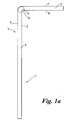
- an L-shaped casing profile 1 comprises a board 2 with an angled cross-section defining a first leg 3 and a second leg 4.
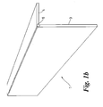
- the joint 5 between the two legs is formed by the wrapping of the board 2 around dowelling 6 the aim being that the side 7 of the board 2 opposite that side 8 in contact with the dowelling 6 defines an unbroken curving surface around the joint 5.
- This means that the profile 1 when viewed from the side 7 give the appearance of a post-formed article with a pleasing finish. This is all the more the case if the side 7 of the casing profile 1 is veneered with wood or a decorative foil, which may comprise a paper, vinyl or melamine foil (see Figs 2 -4).
- the dowelling 6 is preferably of circular cross-section and is located in a channel 9 formed in the side 8 and is adhered to the board 2 by an appropriate adhesive.
- the bottom 10 of the channel 9 is formed by a flexible thickness of the board 1 that has been folded around the dowelling 6 so that the side 7 of the profile 1 is unbroken. This is accomplished as described below.
- both the board 2 and the dowelling 6 are made from medium-density fibreboard (MDF).
- MDF medium-density fibreboard
- the board 2 will have a thickness between 9 mm and 15 mm inclusive and the dowelling 6 will have been cut from MDF board of between one and one third and one and one half the thickness so that its diameter is also of a similar dimension.
- dowelling 6 of MDF it is important that the grain of the dowelling 6 is arranged to lie across the joint 5 of the casing profile at an angle to the two legs 3, 4 of the joint 5. This ensures that the dowelling 6 can withstand pressure applied to the faces of the legs 3, 4 of the casing profile 1 without splitting.
- the casing profile 1 can be manufactured as will now be described.
- the flat board 2 from which the profile 1 is to be made must first be covered on one side 7 with a desired veneer 11 that must be flexible.
- the veneer 11 is adhered to the board 2 in a conventional fashion.
- the opposite side 8 of the board 2 is routed to provide the linear channel 9.
- the depth of the channel 9 must be such that the bottom 10 of the channel 9 is formed by a flexible thickness of the board 2 and veneer 11.
- the bottom of the channel has an overall thickness of around 0.3 mm. However, this thickness varies dependent on the thickness of the veneer 11.
- the board 2 In most cases very little of the MDF is left covering the veneer 11 at the bottom of the channel 9 but is important to have at least a thin MDF skin over the veneer 11 so that there is an MDF to MDF bond with the dowelling 6. The same would apply were the board 2 to be made of another material, such as a plastic.
- the width of the channel 9 determines the extent to which the board 2 can be wrapped around the dowelling 6 and therefore determines the angle formed by the legs 3 and 4 of the casing profile 1. This dimension can therefore be varied according to the angle required and the thickness of the board 2.
- the dowelling 6 preferably has a circular cross-section, the sides 12 of the channel 9 are routed so that they also have a part-circular profile with a curvature the same as that of the dowelling 6.
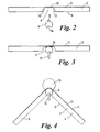
- the dowelling 6 should be cut to the same length as the length of the board 2 and the channel 9. It should then be prepared so that it can be supported by a locator tool 13 (see Fig. 3) whilst the casing profile 1 is made. Preferably, therefore, it is provided with a linear groove 14 or spaced holes or slots into which a portion or portions of the tool 13 can be inserted so that the dowelling can be supported along the whole of its length.
- the doweling 6 should then be located on the tool 13 and a bead of adhesive 15 applied along its length on the opposite side to the groove 14 and the tool 13. Alternatively of in addition, adhesive is applied over the surface of the channel 9 in the board 2.
- the dowelling 6 may be manufactured from MDF boards. In this case it is important that the grain of the dowelling 6 is arranged to lie in a direction parallel with the surfaces 7 and 8 of the board 2 as shown in Figs. 2 and 3 so that in the finished casing profile 1 it lies at an angle to the legs 3 and 4 for the reasons described above.
- the board 2 can be positioned above it as shown in Fig. 2.
- the board 2 can then be lowered so that the supported dowelling 6 is inserted into the channel 9, as shown in Fig. 3.
- a compressible top tool 16 can then be lowered against the upper side 7 of the board 2 directly opposite to the dowelling 6, as shown in Fig. 4.
- Such a top tool 16 may comprise a foam-rubber pressure pad supported in a header (not shown) that applies substantially the same pressure along the length of the dowelling 6.
- the top tool 16 forces the flexible bottom 10 of the channel to wrap around the dowelling 6 and therefore forces the board 2 into an angled cross-section.
- the bead of adhesive 15 is smoothed out and spread over the surface of the dowelling 6.
- the top tool 16 is adapted to apply sufficient pressure to ensure adhesion between the dowelling 6 and the board 6 for a predetermined time sufficient to set the adhesive 15. This is dependent on the adhesive 15 used. In this regard, it is envisaged that a PVA glue will be appropriate for MDF boards 2 and dowelling 6 but it will be appreciated that any suitable adhesive could be applied. Some adhesives may be used that can be cured by exposing the casing profile 1 to radio frequency radiation or similar. This could speed up manufacture of the profile 1. Also, the locator tool 13 is preferably spring-loaded in order to take up any slight variations in the positioning and linearity of the various components and tools being used.
- casing profile 1 can be removed from the locator tool 13 either to enable addition joints to be formed or to be ready for use.
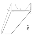
- casing profiles 1 with U-shaped (Fig. 5), C-shaped (Fig. 6) and r-shaped (see Figs. 7 and 8) cross-sectional profiles can be manufactured by the method described above.
- the profiles shown in Figs. 5, 6 and 8 all require two joints 5 to be made in the board 2. All but the C-shaped profile shown in Fig. 6 have the advantage that they will readily nest, facilitating storage prior to installation.
- a further advantage of the present invention over conventional post-formed casings is that the radius of the angled cross-section of the profile can be considerably smaller in the present invention than in post-formed casings.
- the smallest radius that can be post-formed using steaming techniques is typically around 27 mm whereas in the present invention the radius can be as small as 8 mm.
- This enables neater and less bulky casing profiles to be produced.
- the veneering step in the method is easier to accomplish and results in a more successful finish.
- the application of a veneer is usually the last step in the manufacturing process after the profile has been post-formed. This is trickier to carry out successfully.
- casing profiles according to the invention respectively can be used to box-in building structures such as pipework, radiators, electrical cables and other similar fixtures in buildings as required. Large profiles can also be produced as radiator covers. Also, the profiles could be used in the manufacture of furniture, in particular built-in furniture.
- Joining profiles and end-pieces can also be manufactured to match the profiles. It will be appreciated that as the outside surface of the casing profile 1 around the joint 5 is an unbroken curving, in most cases veneered, surface that the profile gives the appearance of being made from post-formed laminates whereas this is not, in fact, the case. As such laminates do not have to be used, the cost of the casing profile 1 is significantly reduced whilst not compromising the attractiveness of its appearance.
Landscapes
- Engineering & Computer Science (AREA)
- Architecture (AREA)
- Civil Engineering (AREA)
- Structural Engineering (AREA)
- Furniture Connections (AREA)
- Tables And Desks Characterized By Structural Shape (AREA)
Applications Claiming Priority (1)
| Application Number | Priority Date | Filing Date | Title |
|---|---|---|---|
| GBGB0505278.2A GB0505278D0 (en) | 2005-03-15 | 2005-03-15 | Casing profile and a method of manufacturing same |
Publications (2)
| Publication Number | Publication Date |
|---|---|
| EP1712704A2 true EP1712704A2 (fr) | 2006-10-18 |
| EP1712704A3 EP1712704A3 (fr) | 2008-06-04 |
Family
ID=34509083
Family Applications (1)
| Application Number | Title | Priority Date | Filing Date |
|---|---|---|---|
| EP06251386A Withdrawn EP1712704A3 (fr) | 2005-03-15 | 2006-03-15 | Profil de boîtier et son procédé de fabrication |
Country Status (2)
| Country | Link |
|---|---|
| EP (1) | EP1712704A3 (fr) |
| GB (2) | GB0505278D0 (fr) |
Citations (6)
| Publication number | Priority date | Publication date | Assignee | Title |
|---|---|---|---|---|
| US2092883A (en) | 1935-02-18 | 1937-09-14 | Rca Corp | Drive system |
| GB520911A (en) | 1938-11-04 | 1940-05-07 | Richard Hubert Crouch | Improvement in round corners for use in cabinet work |
| DE7115696U (de) | 1971-12-30 | Philips Gmbh | Gehäuse für ein technisches Gerät | |
| GB1502218A (en) | 1975-05-22 | 1978-02-22 | Philips Electronic Associated | Cabinet comprising an enclosure and an assembly of panels for forming the enclosure |
| DE8704894U1 (de) | 1987-04-02 | 1988-05-05 | Fa. Buhmann, 7988 Wangen | Innenausbauelement |
| GB2290052A (en) | 1994-06-06 | 1995-12-13 | Kimberly Clark Co | Stretched-thinned film and nonwoven laminate |
Family Cites Families (8)
| Publication number | Priority date | Publication date | Assignee | Title |
|---|---|---|---|---|
| US2092833A (en) * | 1936-10-13 | 1937-09-14 | Richard H Crouch | Round corner |
| GB721086A (en) * | 1952-02-15 | 1954-12-29 | Ejner Robert Tjorn | Improvements in and relating to a method for the production of a fashioned piece of linoleum and apparatus for use in carrying out the method |
| FR2431585A1 (fr) * | 1978-07-21 | 1980-02-15 | Telemecanique Electrique | Couvre-joint deformable, en particulier pour plinthes electriques |
| EP0437660A1 (fr) * | 1990-01-18 | 1991-07-24 | Helmitin Gmbh | Bande de bordure en linoléum |
| ES2107599T3 (es) * | 1992-10-29 | 1997-12-01 | Helmut Wedi | Procedimiento para la fabricacion de productos angulares semiacabados a partir de placas compuestas laminadas. |
| DE9422277U1 (de) * | 1994-05-26 | 1999-09-23 | BHF-Beschichtungswerk B. Hagedorn GmbH & Co., 37696 Marienmünster | Faltplatte, insbesondere Hartfaserplatte |
| GB2290051A (en) * | 1994-06-07 | 1995-12-13 | Tannoy Ltd | Forming panel corners |
| GB9618611D0 (en) * | 1996-09-06 | 1996-10-16 | Itw Ltd | Edge-protectors |
-
2005
- 2005-03-15 GB GBGB0505278.2A patent/GB0505278D0/en not_active Ceased
-
2006
- 2006-03-15 EP EP06251386A patent/EP1712704A3/fr not_active Withdrawn
- 2006-03-15 GB GB0605190A patent/GB2424231B/en not_active Expired - Fee Related
Patent Citations (6)
| Publication number | Priority date | Publication date | Assignee | Title |
|---|---|---|---|---|
| DE7115696U (de) | 1971-12-30 | Philips Gmbh | Gehäuse für ein technisches Gerät | |
| US2092883A (en) | 1935-02-18 | 1937-09-14 | Rca Corp | Drive system |
| GB520911A (en) | 1938-11-04 | 1940-05-07 | Richard Hubert Crouch | Improvement in round corners for use in cabinet work |
| GB1502218A (en) | 1975-05-22 | 1978-02-22 | Philips Electronic Associated | Cabinet comprising an enclosure and an assembly of panels for forming the enclosure |
| DE8704894U1 (de) | 1987-04-02 | 1988-05-05 | Fa. Buhmann, 7988 Wangen | Innenausbauelement |
| GB2290052A (en) | 1994-06-06 | 1995-12-13 | Kimberly Clark Co | Stretched-thinned film and nonwoven laminate |
Also Published As
| Publication number | Publication date |
|---|---|
| GB0605190D0 (en) | 2006-04-26 |
| GB2424231B (en) | 2010-01-27 |
| GB2424231A (en) | 2006-09-20 |
| GB0505278D0 (en) | 2005-04-20 |
| EP1712704A3 (fr) | 2008-06-04 |
Similar Documents
| Publication | Publication Date | Title |
|---|---|---|
| US11480204B2 (en) | Automated assembly | |
| CN100420554C (zh) | 镶面凸板元件其制造方法 | |
| JP3404039B2 (ja) | パネル及びこのパネルの製造方法 | |
| US4402170A (en) | Millwork member of folded construction | |
| US5271878A (en) | Insulating half-log panel | |
| US6584743B2 (en) | Decorative skirting (base) board or crown molding | |
| US20120227345A1 (en) | Universal door skin blank, method of manufacturing a door produced therewith, and door produced therefrom | |
| US6343454B1 (en) | Method of furniture assembly capable of securing and vertically adjusting and aligning edge moldings and trim to a surface | |
| US6740187B2 (en) | Method of producing a window section | |
| EP3079869B1 (fr) | Procédé pour fabriquer un élément de construction préfabriqué | |
| EP3192939A1 (fr) | Plinthe, systeme de décoration et procede de fabrication de plinthe | |
| EP1007306B1 (fr) | Procede de production d'une plaque en fibre de bois incurvee et plaque en fibre de bois ainsi produite | |
| CN111531966B (zh) | 家具用弧形板制作方法及家具用弧形板 | |
| WO2015087150A1 (fr) | Procédé permettant de fabriquer un panneau à structure en nid d'abeille et produit obtenu à partir ce celui-ci | |
| EP1712704A2 (fr) | Profil de boîtier et son procédé de fabrication | |
| JP2016070014A (ja) | パネル体、パネル体の製造方法、パネル体に用いる外装材の製造方法、および、扉構造体 | |
| JP2017053108A (ja) | 見切及び当該見切を用いる見切枠及び建具 | |
| US6399172B1 (en) | Hinged panel for furniture | |
| JP3359617B2 (ja) | 芯材および框材の製造方法 | |
| JP3407296B2 (ja) | 芯材および框材 | |
| JPH049125Y2 (fr) | ||
| CN208294366U (zh) | 具嵌入式装饰条的木质门扇结构 | |
| US20140311688A1 (en) | Clad slat | |
| CN118167176A (zh) | 一种面板组件、门扇及门扇的制作方法 | |
| JPH0357443Y2 (fr) |
Legal Events
| Date | Code | Title | Description |
|---|---|---|---|
| PUAI | Public reference made under article 153(3) epc to a published international application that has entered the european phase |
Free format text: ORIGINAL CODE: 0009012 |
|
| AK | Designated contracting states |
Kind code of ref document: A2 Designated state(s): AT BE BG CH CY CZ DE DK EE ES FI FR GB GR HU IE IS IT LI LT LU LV MC NL PL PT RO SE SI SK TR |
|
| AX | Request for extension of the european patent |
Extension state: AL BA HR MK YU |
|
| PUAL | Search report despatched |
Free format text: ORIGINAL CODE: 0009013 |
|
| AK | Designated contracting states |
Kind code of ref document: A3 Designated state(s): AT BE BG CH CY CZ DE DK EE ES FI FR GB GR HU IE IS IT LI LT LU LV MC NL PL PT RO SE SI SK TR |
|
| AX | Request for extension of the european patent |
Extension state: AL BA HR MK YU |
|
| 17P | Request for examination filed |
Effective date: 20081021 |
|
| AKX | Designation fees paid |
Designated state(s): AT BE BG CH CY CZ DE DK EE ES FI FR GB GR HU IE IS IT LI LT LU LV MC NL PL PT RO SE SI SK TR |
|
| STAA | Information on the status of an ep patent application or granted ep patent |
Free format text: STATUS: THE APPLICATION HAS BEEN WITHDRAWN |
|
| 18W | Application withdrawn |
Effective date: 20100311 |