EP1712850A2 - Heizkörper - Google Patents
Heizkörper Download PDFInfo
- Publication number
- EP1712850A2 EP1712850A2 EP06111641A EP06111641A EP1712850A2 EP 1712850 A2 EP1712850 A2 EP 1712850A2 EP 06111641 A EP06111641 A EP 06111641A EP 06111641 A EP06111641 A EP 06111641A EP 1712850 A2 EP1712850 A2 EP 1712850A2
- Authority
- EP
- European Patent Office
- Prior art keywords
- front portion
- edge portions
- heating element
- radiator
- radiator according
- Prior art date
- Legal status (The legal status is an assumption and is not a legal conclusion. Google has not performed a legal analysis and makes no representation as to the accuracy of the status listed.)
- Withdrawn
Links
- 238000010438 heat treatment Methods 0.000 title claims abstract description 58
- 239000002184 metal Substances 0.000 claims abstract description 4
- 230000001154 acute effect Effects 0.000 claims description 5
- 238000005259 measurement Methods 0.000 claims 1
- 230000000694 effects Effects 0.000 description 3
- LYCAIKOWRPUZTN-UHFFFAOYSA-N Ethylene glycol Chemical compound OCCO LYCAIKOWRPUZTN-UHFFFAOYSA-N 0.000 description 2
- 230000000670 limiting effect Effects 0.000 description 2
- 238000005516 engineering process Methods 0.000 description 1
- 239000013529 heat transfer fluid Substances 0.000 description 1
- WGCNASOHLSPBMP-UHFFFAOYSA-N hydroxyacetaldehyde Natural products OCC=O WGCNASOHLSPBMP-UHFFFAOYSA-N 0.000 description 1
- 239000007788 liquid Substances 0.000 description 1
- 239000000463 material Substances 0.000 description 1
- 230000000191 radiation effect Effects 0.000 description 1
- XLYOFNOQVPJJNP-UHFFFAOYSA-N water Substances O XLYOFNOQVPJJNP-UHFFFAOYSA-N 0.000 description 1
Images


Classifications
-
- F—MECHANICAL ENGINEERING; LIGHTING; HEATING; WEAPONS; BLASTING
- F24—HEATING; RANGES; VENTILATING
- F24H—FLUID HEATERS, e.g. WATER OR AIR HEATERS, HAVING HEAT-GENERATING MEANS, e.g. HEAT PUMPS, IN GENERAL
- F24H3/00—Air heaters
- F24H3/002—Air heaters using electric energy supply
- F24H3/004—Air heaters using electric energy supply with a closed circuit for a heat transfer liquid
Definitions
- the present invention relates to a heating radiator.
- heating radiators and heaters in general have acquired important design aspects in recent years.
- radiators which have a sparing style and are as flat as possible.
- the aim of the present invention is to provide a design-oriented heating radiator which has a particularly low thickness.
- an object of the present invention is to provide a heating radiator which has a reduced edge thickness and at the same time allows to increase the heat radiation effect, thus improving the overall yield of the radiator with respect to known types of comparable radiator.
- Another object of the present invention is to provide a heating radiator which is structurally simple and can be used with heating elements of various types without compromising its design particularities.
- Another object of the present invention is to provide a heating radiator which can be manufactured with known systems and technologies.
- a heating radiator characterized in that it comprises a substantially flat heating element, which is recessed within a jacket made of metal plate which is visible to the radiator user, said jacket being constituted by a front portion, from the side ends of which edge portions protrude which are folded so as to conceal the edge of said heating element, said heating element being in contact with said front portion and being comprised between said edge portions.
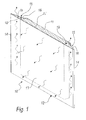
- a first embodiment of a heating radiator according to the invention is generally designated by the reference numeral 10.
- the radiator 10 comprises a heating element 11, which is of a substantially flat type, i.e. has a generally flat shape, and is embedded within a jacket 12, which is visible to the user of the radiator 10.
- the heating element 11 is shown in cross-section for explanatory reasons as if it were a single block; in practice, the heating element 11 can be constituted for example by an electric plate, by a shell-and-tube element within which hot water or a specifically-provided liquid, such as for example glycol, flows, heated by electrical resistors inside the shell-and-tube structure, or by other equivalent heating elements.
- the jacket 12 is constituted by a front portion 13, which is for example rectangular and from the side ends 14 of which edge portions 15 protrude.
- the jacket 12 is made of metal plate, which is folded at its ends so as to form the edge portions 15.
- the edge portions 15 taper outward.
- the outer surfaces 16 of the edge portions 15 form, in this embodiment, an acute angle ⁇ with the internal surface 17 of the front portion 13.
- edge portions 15 and the front portion 13 delimit corner portions; the heating element 11 is comprised between said corner portions.
- corner portions and the side of the heating element 11 delimit respective vertical interspaces 19, which are arranged laterally with respect to the heating element 11.
- Said heating element in practice is in contact with the front portion 13 and is comprised between the edge portions 15.
- the structure thus described shows that the width of the heating element 11 is less than the distance between the lateral ends 14 of the front portion 13 and therefore less than the overall radiating surface.
- the edge portions 15 also protrude from the lower and upper ends (not shown in the figures) of the front portion 13, so as to form in practice a continuous perimetric containment border for the heating element 11.
- Figures 1 and 2 illustrate an example of a first embodiment of the jacket 12; the heating element 11 is shown in broken lines and the radiated heat is shown schematically by a plurality of wavy arrows.
- edge portions 15 end with a bend 20 for the containment and abutment of the lateral end of the heating element 11 and have an end portion 21 which is parallel to the front portion 13 and is designed to lock in a sandwich-like fashion the heating element 11.
- the bend 20 forms a discontinuity on the region of the edge portion 15 which is inclined by the angle ⁇ on the internal surface of the plate-like front portion 13.
- FIG 3 illustrates an example of an alternative embodiment of the jacket, designated generally by the reference numeral 112, in which the containment and abutment bend described earlier is not present; in this case also, the heating element 111 is shown in broken lines.
- the edge portions 115 have an end region 121, which is simply folded with respect to the region of the edge portion 115 which is inclined by the angle ⁇ with respect to the internal surface of the front portion 113 and is parallel to the front portion 113 and adapted to lock in a sandwich-like fashion the heating element 111.
- lateral containment is provided by the region of the edge portion 115 which is inclined by the angle ⁇ with respect to the internal surface of the front portion 113.
- FIG. 4 illustrates another embodiment of the jacket, generally designated by the reference numeral 212; in this case also, the heating element 211 is shown in broken lines.
- edge portions 215 also taper outward; the edge portions 215 in fact have a first part 215a, which is inclined toward the wall to which the radiator is to be fixed, and a second tip part 215b, which is parallel to the front portion 213.
- FIG. 5 illustrates another embodiment of the jacket, generally designated by the reference numeral 312; in this case also, the heating element 311 is shown in broken lines.
- edge portions 315 also taper outward; the edge portions 315 in practice are formed by a portion 315a, which is bent in the shape of a circular arc, and a portion 315b, which is parallel to the front portion 313.
- FIG 6 illustrates another embodiment of the jacket, generally designated by the reference numeral 412; in this case also, the heating element 411 is shown in broken lines.
- the edge portions 415 are folded along a first region 415a, which is perpendicular to the front portion 413, and a second region 415b, which is perpendicular to the first portion 415a.
- the present invention in fact provides a radiator which is constituted by a flat heating element, which can be of various kinds and can have a low-quality aesthetic finish, and by a jacket, which covers said flat heating element and has a very low thickness.
- Such jacket does not compromise the flat appearance of the radiator as a whole and at the same time conceals the heating element, which therefore can be produced without a high-quality finish and therefore at a lower cost than an externally-finished heating element.
- the jacket allows to protect the heating element against impact, particularly in the edge regions; in these regions, the deformation in fact affects only the interspace of the jacket and does not affect the heating element.
- a radiating surface has been provided which has a larger area than the radiating surface of a plate which is perfectly superimposed on the heating element.
- the radiating surface of the front portion of the jacket which lies beyond the contact surface with the heating element is heated not only by conduction by the rest of the plate but also as an effect of the convection generated within the interspaces.
- the overall heat yield is higher than that of a plate which rests against a heating element of equal size.
- the depth of the jacket 12 is comprised preferably substantially, i.e. to a large extent, between 6% and 8% of the height of said jacket, while the horizontal dimensions or extensions of the projections on said plate-like front portion 13 of the edge portions 15 are comprised substantially between 1% and 2% of the height of the jacket 12.
- the acute angle ⁇ formed by the outer surfaces is preferably comprised for example substantially between 9° and 21°.
- the materials employed may be any according to requirements and to the state of the art.
Landscapes
- Engineering & Computer Science (AREA)
- Physics & Mathematics (AREA)
- Thermal Sciences (AREA)
- Chemical & Material Sciences (AREA)
- Combustion & Propulsion (AREA)
- Mechanical Engineering (AREA)
- General Engineering & Computer Science (AREA)
- Central Heating Systems (AREA)
- Domestic Hot-Water Supply Systems And Details Of Heating Systems (AREA)
- Resistance Heating (AREA)
Applications Claiming Priority (1)
| Application Number | Priority Date | Filing Date | Title |
|---|---|---|---|
| IT000026U ITPD20050026U1 (it) | 2005-04-13 | 2005-04-13 | Radiatore per uso riscaldamento |
Publications (2)
| Publication Number | Publication Date |
|---|---|
| EP1712850A2 true EP1712850A2 (de) | 2006-10-18 |
| EP1712850A3 EP1712850A3 (de) | 2007-07-25 |
Family
ID=36694136
Family Applications (1)
| Application Number | Title | Priority Date | Filing Date |
|---|---|---|---|
| EP06111641A Withdrawn EP1712850A3 (de) | 2005-04-13 | 2006-03-23 | Heizkörper |
Country Status (3)
| Country | Link |
|---|---|
| US (1) | US20060231548A1 (de) |
| EP (1) | EP1712850A3 (de) |
| IT (1) | ITPD20050026U1 (de) |
Families Citing this family (1)
| Publication number | Priority date | Publication date | Assignee | Title |
|---|---|---|---|---|
| CN112361437B (zh) * | 2020-12-01 | 2022-07-26 | 湖南全康电子科技有限公司 | 一种折叠式电暖气 |
Citations (1)
| Publication number | Priority date | Publication date | Assignee | Title |
|---|---|---|---|---|
| ITPD20050026A1 (it) | 2005-02-08 | 2006-08-09 | Pasta Technologies Srl | Attrezzatura per la produzione di ravioli e simili |
Family Cites Families (12)
| Publication number | Priority date | Publication date | Assignee | Title |
|---|---|---|---|---|
| US2460625A (en) * | 1945-10-31 | 1949-02-01 | William A Ellis | Baseboard room heater |
| US3582614A (en) * | 1967-11-03 | 1971-06-01 | Mabel W Zellers | Radiant heating module |
| US3612823A (en) * | 1970-01-08 | 1971-10-12 | Mearl E Ellison | Combined decorative picture and electric room-heating device |
| US3691345A (en) * | 1970-06-18 | 1972-09-12 | Continental Radiant Glass Heat | Radiant heater |
| US5138134A (en) * | 1984-02-10 | 1992-08-11 | Ellison Mearl E | Decorative wall hanging heater |
| AT386890B (de) * | 1984-03-23 | 1988-10-25 | Vogel & Noot Ag | Verkleidung fuer heizkoerper |
| DE8810045U1 (de) * | 1988-08-03 | 1988-09-29 | Kermi GmbH, 8350 Plattling | Plattenheizkörper mit Umrahmung |
| DE8907421U1 (de) * | 1989-06-19 | 1989-08-31 | Kermi GmbH, 8350 Plattling | Verkleidung für Heizkörper |
| US4922084A (en) * | 1989-08-28 | 1990-05-01 | Gerhard Hutter | Uni-directional heating apparatus |
| US5214739A (en) * | 1992-01-16 | 1993-05-25 | Nelson Thomas M | Localized heating unit for desks |
| DE29912593U1 (de) * | 1999-07-20 | 1999-11-04 | Ulamo Beheer B.V., Ulft | Frontpaneele |
| DE102004014606B3 (de) * | 2004-03-23 | 2005-08-11 | Wiemann Gmbh | Verkleidungsplatte für die Frontseite eines Heizkörpers sowie Verfahren zur Herstellung der Verkleidungsplatte |
-
2005
- 2005-04-13 IT IT000026U patent/ITPD20050026U1/it unknown
-
2006
- 2006-03-23 EP EP06111641A patent/EP1712850A3/de not_active Withdrawn
- 2006-03-27 US US11/389,204 patent/US20060231548A1/en not_active Abandoned
Patent Citations (1)
| Publication number | Priority date | Publication date | Assignee | Title |
|---|---|---|---|---|
| ITPD20050026A1 (it) | 2005-02-08 | 2006-08-09 | Pasta Technologies Srl | Attrezzatura per la produzione di ravioli e simili |
Also Published As
| Publication number | Publication date |
|---|---|
| ITPD20050026U1 (it) | 2006-10-14 |
| EP1712850A3 (de) | 2007-07-25 |
| US20060231548A1 (en) | 2006-10-19 |
Similar Documents
| Publication | Publication Date | Title |
|---|---|---|
| US9181747B2 (en) | Door for home appliance and method for manufacturing the same | |
| US8180205B2 (en) | Electrothermal oil radiator | |
| AU1636000A (en) | Independently operating mobile radiator | |
| EP2975976B1 (de) | Elektrischer reiskocher | |
| CN104279820B (zh) | 冰箱门体 | |
| EP1712850A2 (de) | Heizkörper | |
| CN207455259U (zh) | 一种led灯 | |
| WO2014076511A1 (en) | Construction of toaster (contact grill) or sandwich toaster with the use of heat reflection group | |
| CN109951972B (zh) | 壳体组件、终端设备及壳体组件的组装方法 | |
| JP6189677B2 (ja) | 加熱調理器 | |
| US12234998B1 (en) | Tamper-resistant baseboard heater cover assembly | |
| CN207560600U (zh) | 散热器 | |
| EP3851762B1 (de) | Flüssigkeitserhitzer | |
| CN210951425U (zh) | 电磁炉 | |
| CN101472441A (zh) | 散热器 | |
| CN202425271U (zh) | 一种热管固定座改良结构 | |
| CN220608161U (zh) | 一种改良防粘结构的煎盘 | |
| CN221946446U (zh) | 一种嵌入式的机箱结构 | |
| CN203789674U (zh) | 烹饪器具的外壳和烹饪器具 | |
| JP4028568B2 (ja) | グリル扉 | |
| CN205883809U (zh) | 回形散热器铝型材 | |
| CN210298117U (zh) | 一种带金属包边的ptc发热芯片 | |
| CN215914150U (zh) | 烹饪器具及其锅体 | |
| CN216976884U (zh) | 一种带辐射式电暖器 | |
| CN211959885U (zh) | 一种错落型散热片结构 |
Legal Events
| Date | Code | Title | Description |
|---|---|---|---|
| PUAI | Public reference made under article 153(3) epc to a published international application that has entered the european phase |
Free format text: ORIGINAL CODE: 0009012 |
|
| AK | Designated contracting states |
Kind code of ref document: A2 Designated state(s): AT BE BG CH CY CZ DE DK EE ES FI FR GB GR HU IE IS IT LI LT LU LV MC NL PL PT RO SE SI SK TR |
|
| AX | Request for extension of the european patent |
Extension state: AL BA HR MK YU |
|
| PUAL | Search report despatched |
Free format text: ORIGINAL CODE: 0009013 |
|
| AK | Designated contracting states |
Kind code of ref document: A3 Designated state(s): AT BE BG CH CY CZ DE DK EE ES FI FR GB GR HU IE IS IT LI LT LU LV MC NL PL PT RO SE SI SK TR |
|
| AX | Request for extension of the european patent |
Extension state: AL BA HR MK YU |
|
| RIC1 | Information provided on ipc code assigned before grant |
Ipc: F24D 19/06 20060101ALI20070619BHEP Ipc: F24D 13/04 20060101ALI20070619BHEP Ipc: F24H 3/00 20060101AFI20060801BHEP |
|
| 17P | Request for examination filed |
Effective date: 20080125 |
|
| 17Q | First examination report despatched |
Effective date: 20080225 |
|
| AKX | Designation fees paid |
Designated state(s): AT BE BG CH CY CZ DE DK EE ES FI FR GB GR HU IE IS IT LI LT LU LV MC NL PL PT RO SE SI SK TR |
|
| STAA | Information on the status of an ep patent application or granted ep patent |
Free format text: STATUS: THE APPLICATION IS DEEMED TO BE WITHDRAWN |
|
| 18D | Application deemed to be withdrawn |
Effective date: 20130429 |