EP1712871B1 - Vorrichtung zur Kopplung eines Granatwerfers mit einem automatischen Gewehr - Google Patents
Vorrichtung zur Kopplung eines Granatwerfers mit einem automatischen Gewehr Download PDFInfo
- Publication number
- EP1712871B1 EP1712871B1 EP05425213A EP05425213A EP1712871B1 EP 1712871 B1 EP1712871 B1 EP 1712871B1 EP 05425213 A EP05425213 A EP 05425213A EP 05425213 A EP05425213 A EP 05425213A EP 1712871 B1 EP1712871 B1 EP 1712871B1
- Authority
- EP
- European Patent Office
- Prior art keywords
- automatic rifle
- coupling
- grenade launcher
- barrel
- frame
- Prior art date
- Legal status (The legal status is an assumption and is not a legal conclusion. Google has not performed a legal analysis and makes no representation as to the accuracy of the status listed.)
- Expired - Lifetime
Links
- 238000010168 coupling process Methods 0.000 title claims abstract description 127
- 238000005859 coupling reaction Methods 0.000 title claims abstract description 127
- 230000008878 coupling Effects 0.000 title claims abstract description 113
- 230000002146 bilateral effect Effects 0.000 claims description 7
- 230000001419 dependent effect Effects 0.000 claims description 3
- 238000010304 firing Methods 0.000 description 3
- 230000001681 protective effect Effects 0.000 description 2
- 238000007792 addition Methods 0.000 description 1
- 238000007599 discharging Methods 0.000 description 1
- 230000003993 interaction Effects 0.000 description 1
- 238000004519 manufacturing process Methods 0.000 description 1
- 230000004048 modification Effects 0.000 description 1
- 238000012986 modification Methods 0.000 description 1
Images




Classifications
-
- F—MECHANICAL ENGINEERING; LIGHTING; HEATING; WEAPONS; BLASTING
- F41—WEAPONS
- F41C—SMALLARMS, e.g. PISTOLS, RIFLES; ACCESSORIES THEREFOR
- F41C27/00—Accessories; Details or attachments not otherwise provided for
- F41C27/06—Adaptations of smallarms for firing grenades, e.g. rifle grenades, or for firing riot-control ammunition; Barrel attachments therefor
Definitions
- the object of the present invention is a device for coupling a grenade launcher with an automatic rifle.
- the object of the present invention is a kit for an automatic rifle, a frame for an automatic rifle and a gun fore-end of an automatic rifle.
- the problem at the heart of the present invention is to provide a device for coupling a grenade launcher with an automatic rifle which has such structural and functional characteristics as to meet said need and, while overcoming said drawbacks mentioned with reference to the prior art.
- the carrying out of a mutual shape coupling a first portion of which is directly associated to the gun fore-end of the automatic rifle makes the weapon more compact, simpler and stronger. Furthermore the weapon strength is incremented by providing a rear and lower portion of the gun fore-end directly associated to the frame of the automatic rifle. This characteristic may be achieved either by a gun fore-end being integral and made as one piece with the rifle frame, or by a gun fore-end comprising a lower and rear portion adapted to define a rear and lower fastening point directly on the frame of the automatic rifle.
- Fig. 1 shows a schematic side view of a first embodiment of an automatic rifle and a coupling device in accordance with the present invention
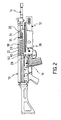
- Fig. 2 shows the automatic rifle from Fig. 1 associated to a grenade launcher
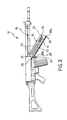
- Fig. 3 shows the automatic rifle from Fig. 1 in a mounting step
- Fig. 4 shows the automatic rifle from Fig. 1 in a different operating condition
- Fig. 5 shows a perspective view of a detail of the automatic rifle from Fig. 1 ;
- Fig. 6 shows a cut-away perspective view of the automatic rifle, grenade launcher and coupling device according to the present invention
- Fig. 7 shows a longitudinal sectional view of a detail from Fig. 2 ;
- Fig. 8 shows a sectional view according to line VII-VII from Fig. 7 ;
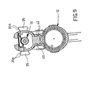
- Fig. 9 shows a sectional view according to line IX-IX from Fig. 7 ;
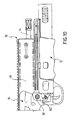
- Fig. 10 shows a schematic side view of a further embodiment of an automatic rifle, the grenade launcher and the coupling device in accordance with the present invention
- Fig. 11 shows the automatic rifle from Fig. 10 in which the grenade launcher has been omitted in order to highlight a part of the coupling device according to the present invention.
- FIG. 1 shows a schematic side view of a first embodiment of an automatic rifle 10 in accordance with the present invention.
- Fig. 2 shows automatic rifle 10 from Fig. 1 associated to grenade launcher 12.
- Fig. 3 shows the automatic rifle 10 from Fig. 1 in a mounting step, and finally
- Fig. 4 shows the automatic rifle from Fig. 1 in a different operating condition.
- a first aspect of the present invention relates to a device for coupling the grenade launcher 12 with the automatic rifle 10.
- this coupling device comprises a gun fore-end 18 of the automatic rifle, which is integral to the barrel 14 of the automatic rifle.
- Fig. 1-9 show a first embodiment of the coupling device according to the present invention in which the gun fore-end 18 is provided by means of an element being detached from the frame of the automatic rifle and adapted to be fastened to the frame and the barrel of the automatic rifle.
- the gun fore-end 18 is adapted to embrace the barrel 14 of the automatic rifle at the lower side and sideways thereof.
- Fig. 5 shows a perspective view of an exemplary embodiment of the gun fore-end 18, in which with 20 has been indicated a wrapping portion embracing the barrel of the automatic rifle at the lower side and sideways thereof.
- the wrapping portion 20 overhangs the barrel 14 of the automatic rifle on either side at least in one front portion 22 of the gun fore-end.
- wrapping walls 23 of the gun fore-end 18 are adapted to wrap the barrel 14 of the automatic rifle on either side.
- a rear and lower portion of the gun fore-end 18 is adapted to be directly fastened onto the frame 16 of the automatic rifle.
- this rear and lower portion of the gun fore-end comprises a tooth 24 extending on the lower and rear sides of the gun fore-end in order to be inserted in a slot, not shown, of the automatic rifle frame 16. This slot is located at the lower side of the barrel 14 of the automatic rifle.
- the tooth 24 extends in the lower and rear sides in a cantilever manner relative to the wrapping walls 23 of barrel 14.
- the tooth 24 is directly fastened onto the frame 16 of the automatic rifle in order to define a rear fastening point on the gun fore-end.
- this rear fastening point allows the gun fore-end to be free to rotate around an axis 26 transversal to the barrel of the automatic rifle ( Fig. 3 ).
- the rear fastening point comprises a coupling pivot 28 being transversally inserted between the gun fore-end 18 and the frame 16 of the automatic rifle, at tooth 24.
- the tooth 24 has a cross hole 30 in order to accommodate the coupling pivot 28 and the rifle frame comprises its respective side holes 31.
- the coupling between the coupling pivot 28 and the tooth 24 allows the gun fore-end to be free only to rotate around axis 26 between an inserting position of the tooth into the slot ( Fig. 3 ) and a mounting position of the gun fore-end 18 on the barrel 14 of the automatic rifle ( Fig. 1 ).
- the front portion 22 of the gun fore-end 18 has inserting seats 32 for a cross fastener 34 adapted to rest on the upper side of the barrel of the automatic rifle in order to fasten the front portion 22 of the gun fore-end.
- a cross fastener 34 is shown in which there is provided a portion 34a having a section conjugate to the shape of the inserting seat 32, for example "T-shaped".
- the portion 34a defines for example a striking element against the rifle barrel.
- the cross fastener 34 extends from one side to another of the front portion 22 of the gun fore-end 18, thus being firmly hung on the rifle barrel.
- the gun fore-end 18 is advantageously fastened to the front and upper sides of the barrel and directly to the rear and lower sides of the frame of the automatic rifle, at a lower area than the same barrel.
- the gun fore-end 18 comprises at least one sidetrack 35 adapted to accommodate some accessories such as front sights or other equipment.
- the sidetrack 35 is provided in the gun fore-end 18 as one piece.
- the sidetrack 35 has a "T-shaped" cross section preferably comprising sloping surfaces 35a adapted to define a bilateral fastening for the accessory.
- the sidetrack 35 has a plurality of notches 35b being located transversal to the rifle barrel at an outer surface of the track.
- the shape, size and arrangement of these notches are adapted to allow the accessories to be locked in certain positions along the length of the same track.
- the gun fore-end 18 comprises two sidetracks 35 either for mounting more accessories or in order to allow front sights or other accessories to be right or left mounted.
- the gun fore-end 18 has a first portion of mutual shape-coupling means externally between the frame of the grenade launcher and the gun fore-end.
- the gun fore-end is manufactured as one piece in polymeric material.
- a second portion of the mutual shape-coupling means, and accordingly the coupling device according to the present invention, is externally associated to a frame 36 of grenade launcher 12.
- the second portion of the mutual shape coupling means is provided in the frame 36 of the grenade launcher as one piece, for example manufactured in polymeric material.
- the first and second portions mutually slide one inside the other along a direction which is parallel to the barrel 14 of the automatic rifle in order to fasten the grenade launcher to the automatic rifle in a direction which is transversal to the barrel of the automatic rifle.
- the first portion comprises a track 38 being directly associated to the gun fore-end 18 and extending in the lower side of and parallel to barrel 14 of the automatic rifle between a front end 38a and a rear end 38b.
- the track 38 is provided as one piece with the gun fore-end 18.
- the second portion comprises a sliding seat 40 being defined in the frame 36 of the grenade launcher and extending in the upper side of the grenade launcher and parallel to the barrel 14 of the automatic rifle between a front end 40a and a rear end 40b.
- the sliding seat 40 is provided as one piece with the frame 36 of the grenade launcher.
- the sliding seat 40 is capable of being slidingly engaged on the track 38 from the front end 38a to the rear end 38b of the same track in order to fasten the grenade launcher to the automatic rifle in a direction which is transversal to the barrel of the automatic rifle. More precisely, the coupling between track 38 and sliding seat 40 causes the grenade launcher to be fastened onto the automatic rifle in a plane that is perpendicular to the barrel of the automatic rifle.
- the track 38 has a "T-shaped" cross section preferably comprising sloping surfaces 42 adapted to define a bilateral fastening which transversally locks the grenade launcher to the rifle barrel.
- the track 38 has a plurality of notches 44 being located transversal to the rifle barrel at an outer and lower surface of the track.
- the shape, sizes and arrangement of these notches are adapted to allow, in certain positions along the same track, accessories (not shown) to be locked, when the grenade launcher is not mounted on the automatic rifle.
- the gun fore-end comprises tooth 24
- this tooth is preferably arranged as a rear and lower extension of track 38.
- the tooth 24 is arranged as a rear and lower extension of the first portion of the mutual shape-coupling means.
- the rear and lower portion of the gun fore-end 18 adapted to be fastened directly onto the frame 16 of the automatic rifle is arranged as a rear and lower extension of track 38, or more generally the first portion of the mutual shape-coupling means.
- the track 38 extends in the lower side along the length of the wrapping walls 23 and the tooth 24 projects from the rear end of the track in a cantilever manner.
- the rear end of the sliding seat 40 defines an abutment surface 46 adapted to abut against a striking surface 48 associated to the gun fore-end.
- the striking surface 48 is located at a portion of the gun fore-end directly associated to frame 16 of the automatic rifle.
- the striking surface 48 is provided at the rear and lower portion of the gun fore-end adapted to be fastened directly onto the frame 16 of the automatic rifle.
- the striking surface 48 is defined by the same tooth extending in the lower side of track 38.
- the coupling device comprises interference means adapted to act as a constraint for the relative sliding motion between the automatic rifle and the grenade launcher, parallel to the barrel of the automatic rifle.
- the striking surface 48 is located, in an assembled position of the grenade launcher and the automatic rifle, at the front side of the interference means.
- the interference means comprise an interference pivot 50 being transversally inserted between frame 36 of the grenade launcher and gun fore-end 18.
- the interference pivot 50 is located at the rear side of the mutual abutment 46 and striking 48 surfaces of sliding seat 40 and track 38.
- the interference means transversally pass through said tooth.
- the tooth 24 comprises a housing slot 51 in order to accommodate the interference pivot 50.
- the cross hole 30 of tooth 24 adapted to accommodate the coupling pivot 28 is located at the rear side of the housing slot 51 of the interference pivot 50 of the interference means.
- the interference means comprise at least one elastic element 52 adapted to transversally lock the interference pivot 50 between the frame of the grenade launcher and the gun fore-end.
- the interference pivot 50 is hollow inside and the elastic element 52 is housed therein.
- a coupling portion 54 of the elastic element 52 is adapted to pass through an aperture 56 of the interference pivot 50 and be inserted into a recess 58, for example of the housing slot 51 of gun fore-end 18.
- the coupling device comprises at least one fastening wing 60 extending from the frame of the grenade launcher on the rear side of its respective sliding seat 40.
- the fastening wing comprises a housing 62 for the interference pivot 50.
- the frame 36 of the grenade launcher comprises two fastening wings 62 extending from the frame of the grenade launcher on the rear side and the opposite sides of their respective sliding seat 40.
- Each fastening wing 62 comprises a respective housing 62 for the interference pivot 50.
- the two fastening wings 62 are further adapted to be arranged externally on the opposite sides of the gun fore-end, for example at tooth 24, if provided.
- Fig. 3 shows a mounting step of the gun fore-end 18 on the automatic rifle.
- the tooth 24 has been inserted into its respective slot of the rifle frame and the coupling pivot 28 has been inserted into the side holes 31 of the frame and the cross hole 30 of tooth 24.
- a rear fastening point of the gun fore-end that allows the latter to be free to rotate around axis 26 in order to embrace the rifle barrel has been defined directly on the rifle frame.
- FIG. 1 shows the subsequent mounting step in which the gun fore-end is caused to rotate until it embraces the rifle barrel and is fastened onto the front and upper side of the latter.
- the cross fastener 34 is set into inserting seats 32 such that the gun fore-end 18 is hung on the front side of the rifle barrel.
- the thus arranged automatic rifle may be employed both with the grenade launcher 12 ( Fig. 2 ) and individually ( Fig. 1 or 4 ).
- a possible embodiment such as shown for example in Fig. 4 , provides a covering element 64 associated to the first portion of the mutual shape-coupling means.
- the covering element expands so as to cover at least one portion of track 38 and comprises a sliding seat, not shown, similar to the one provided in the frame 36 of grenade launcher 12.
- the covering element 64 is locked on the gun fore-end 18 by means of the interference pivot 50.
- a further aspect of the present invention relates to a kit comprising a gun fore-end 18 adapted to be mounted on an automatic rifle by a lower and rear fastening directly onto the rifle frame and a front and upper fastening being provided such that a front portion of the gun fore-end is hung on the front side of the rifle barrel.
- the kit further comprises either at least one covering element 64, or more covering elements being different from one another in shape, size, material, surface cover or other features.
- the kit further comprises at least one grenade launcher, the frame of which comprises a second portion of mutual shape-coupling means adapted to be coupled with a first portion of mutual shape-coupling means being associated to the gun fore-end, such as described above.
- a further aspect of the present invention relates to a kit comprising an automatic rifle, the frame of which comprises a gun fore-end, integrally and as one piece.
- the kit further either comprises at least one covering element 64, or more covering elements being different from one another in shape, size, material, surface cover or other features.
- the kit further comprises at least one grenade launcher, the frame of which comprises a second portion of mutual shape-coupling means adapted to be coupled with a first portion of mutual shape-coupling means associated to the gun fore-end, such as described above.
- the coupling portion according to the present invention enables to achieve an optimum compromise between lightness and resistance.
- the coupling device Since the first portion of shape coupling means is directly associated to the gun fore-end, the coupling device is made simpler and further adapted to be provided with a gun fore-end being manufactured as one piece.
- a track/sliding seat coupling facilitates and stabilizes the assembling, also due to the configuration of the cross section in which there are provided sloping surfaces adapted to provide a bilateral fastening between the rifle and the grenade launcher. Moreover both the track shape and the presence of the notches make the same track very versatile and adapted for the standardized use as a coupling element for accessories.
- the advantageous configuration of the interference means and particularly the arrangement thereof in a rear position relative to their respective abutment and striking surfaces facilitates the manufacture and the assembly, besides making the step of discharging the impulse due to the firing on the rifle frame more effective.
- a tooth 24 extending the track 38 and being inserted into and associated directly to the rifle frame on the lower side of the barrel is provided, thus making the mutual interaction between the abutment and striking surfaces even more effective and more resistant following the firing.
- the gun fore-end is mounted on the rifle frame by means of a rear and lower fastening point which allows the latter to rotate only around a cross axis, thereby making the gun fore-end positioning on the rifle barrel immediate and firm. Furthermore the gun fore-end is mounted onto the front and upper sides of the rifle barrel, thus making the fastening particularly firm due to the provision of two opposite points relative to the barrel.
- a further advantage of the coupling device according to the invention is the unusual structural simplicity of the latter, which allows the latter to be manufactured with a very low cost.
- Fig. 10 and Fig. 11 illustrate a different embodiment of the coupling device according to the present invention corresponding to what has been described above, except that the gun fore-end is made integral and as one piece with the frame 16 of the automatic rifle 10.
- the term "gun fore-end” will be employed in order to show the portion of frame 16 of automatic rifle 10 which corresponds to the gun fore-end 18 being described above, i.e. the portion embracing the barrel of the automatic rifle.
- the gun fore-end 18 also has a first portion of mutual shape coupling means on the outside thereof, between the frame 36 of the grenade launcher and the gun fore-end.
- the coupling device comprises a second portion of the mutual coupling means being externally associated to the frame 36 of the grenade launcher.
- the first and second portions are mutually sliding one inside the other along a direction which is parallel to the barrel of the automatic rifle in order to fasten the grenade launcher to the automatic rifle in a direction which is transversal to the barrel of the automatic rifle.
- the rear end 40b of sliding seat 40 defines the abutment surface 46 adapted to abut against the striking surface 48 located at a portion directly associated to a frame of the automatic rifle.
- the striking surface 48 is located at a portion made as one piece with the frame of the automatic rifle.
- the striking surface 48 is located, in an assembled position of the grenade launcher and the automatic rifle, at the front side of the interference means being adapted to provide a constraint for the relative sliding motion between the automatic rifle and the grenade launcher, parallel to the barrel of the automatic rifle.
- These interference means may comprise, for example, the interference pivot 50 such as described above.
- the interference pivot 50 is located on the rear side of the abutment and striking surfaces of the sliding seat and the track, respectively.
- the shape of the frame 36 of the grenade launcher may be similar to the one previously described.
- at least one fastening wing 60 extending from the frame of the grenade launcher on the rear side of its respective sliding seat and comprising a housing for the interference pivot.
- the present invention relates to a gun fore-end 18 adapted to be fastened directly onto a frame of the automatic rifle.
- the gun fore-end has externally a first portion of mutual shape-coupling means with a second portion externally associated to an additional device, such as a frame of a grenade launcher, an accessory or a covering element 64.
- the first and second portions are adapted to mutually slide one inside the other along a direction which is parallel to the barrel of the automatic rifle in order to fasten the additional device to the automatic rifle in a direction which is transversal to the barrel of the automatic rifle.
- the gun fore-end has a rear and lower portion adapted to be made integral directly to a frame of the automatic rifle such as to provide a lower fastening point as previously described.
- the rear and lower portion of the gun fore-end is provided in the shape of a tooth 24 such as described above.
- the present invention relates to a frame of an automatic rifle having a gun fore-end integrally and as one piece as described above.
- the portion defining the gun fore-end has externally a first portion of mutual shape-coupling means with a second portion externally associated to an additional device, such as a frame of a grenade launcher, an accessory or a covering element 64.
- the first and second portions are adapted to mutually slide one inside the other along a direction which is parallel to the barrel of the automatic rifle in order to fasten the additional device to the automatic rifle in a direction which is transversal to the barrel of the automatic rifle.
Landscapes
- Engineering & Computer Science (AREA)
- General Engineering & Computer Science (AREA)
- Toys (AREA)
- Telescopes (AREA)
Claims (57)
- Einrichtung zum Koppeln eines Granatwerfers (12) mit einem automatischen Gewehr (10), wobei die Koppeleinrichtung ein Pistolen-Vorderende (18) des automatischen Gewehrs (10) umfasst, welches fest an einem Rohr (14) des gleichen automatischen Gewehrs befestigt ist und welches ein erstes Teil einer gegenseitigen Formkoppeleinrichtung extern zwischen einem Rahmen (36) des Granatwerfers (12) und dem Pistolen-Vorderende (18) hat,
wobei die Koppeleinrichtung außerdem ein zweites Teil der gemeinsamen Koppeleinrichtung hat, welches extern mit einem Rahmen (36) des Granatwerfers (12) in Verbindung steht, und
wobei das erste und das zweite Teil innerhalb des anderen längs einer Richtung gegenseitig verschiebbar ist, welche parallel zum Rohr (14) des automatischen Gewehrs (10) ist, um eine zweiseitige Befestigung zwischen dem Granatwerfer (12) und dem automatischen Gewehr (10) in einer Ebene senkrecht zum Rohr (14) des automatischen Gewehrs (10) zu begrenzen;
wobei die Koppeleinrichtung dadurch gekennzeichnet ist, dass das zweite Teil der gegenseitigen Koppeleinrichtung eine Auflagerfläche (46) umfasst, die angepasst ist, gegen eine anschlagende Fläche (48) anzustoßen, welche mit dem Pistolen-Vorderende (18) verbunden ist, und in einem Bereich unmittelbar befestigt darauf oder als ein Stück mit einem Rahmen (16) des automatischen Gewehrs (10) angeordnet ist. - Einrichtung zum Koppeln eines Granatwerfers (12) mit einem automatischen Gewehr (10) nach Anspruch 1, wobei das erste Teil eine Bahn (38) umfasst, welche unmittelbar mit dem Pistolen-Vorderende (18) verbunden ist und sich auf der unteren Seite von und parallel zum Rohr (14) des automatischen Gewehrs (10) zwischen einem vorderen Ende (38a) und einem hinteren Ende (38b) erstreckt, und
wobei das zweite Teil einen Gleitsitz (40) umfasst, der in einem Rahmen (36) Granatwerfers (12) begrenzt ist und sich in der oberen Seite des Granatwerfers (12) und parallel zum Zylinder (14) des automatischen Gewehrs (10) zwischen einem vorderen Ende (40a) und einem hinteren Ende (40b) erstreckt, wobei der Gleitsitz (40) in der Lage ist, auf der Bahn (38) vom vorderen Ende (38a) zum hinteren Ende (38b) der Bahn gleitend in Eingriff zu sein, um den Granatwerfer (12) am automatischen Gewehr (10) in einer Richtung zu befestigen, welche quer zum Rohr (14) des automatischen Gewehrs (10) ist. - Einrichtung zum Koppeln eines Granatwerfers (12) mit einem automatischen Gewehr (10) nach Anspruch 2, wobei das hintere Ende des Gleitsitzes (40) eine Auflagerfläche (46) begrenzt, die angepasst ist, gegen eine anschlagende Fläche (48) anzustoßen, welche mit dem Pistolen-Vorderende (18) in Verbindung steht ist, und an einem Bereich unmittelbar verbunden mit einem Rahmen (16) des automatischen Gewehrs (10) angeordnet ist.
- Einrichtung zum Koppeln eines Granatwerfers (12) mit einem automatischen Gewehr (10) nach Anspruch 3, wobei die anschlagende Fläche (48) in einer montierten Position des Granatwerfers (12) und des automatischen Gewehrs (10) auf der vorderen Seite einer Eingreifeinrichtung angeordnet ist, die angepasst ist, einen Zwang zur relativen Gleitbewegung zwischen dem automatischen Gewehr (10) und dem Granatwerfer (12) parallel zum Rohr (14) des automatischen Gewehrs (10) auszuüben.
- Einrichtung zum Koppeln eines Granatwerfers (12) mit einem automatischen Gewehr (10) nach Anspruch 4, wobei die Eingreifeinrichtung einen Eingreifdrehzapfen (50) umfasst, der quer zwischen dem Rahmen (36) des Granatwerfers (12) und dem Pistolen-Vorderende (18) eingeführt ist.
- Einrichtung zum Koppeln eines Granatwerfers (12) mit einem automatischen Gewehr (10) nach Anspruch 5, wobei der Eingreifdrehzapfen (50) auf der hinteren Seite des gegenseitigen Auflagers (46) und anschlagenden Flächen (48) des Gleitsitzes (40) und der Bahn (38) angeordnet ist.
- Einrichtung zum Koppeln eines Granatwerfers (12) mit einem automatischen Gewehr (10) nach Anspruch 5 oder 6, wobei die Eingreifeinrichtung zumindest ein federndes Element (52) umfasst, welches angepasst ist, quer den Eingreifdrehzapfen (50) zwischen dem Rahmen (36) des Granatwerfers (12) und dem Pistolen-Vorderende (18) zu verriegeln.
- Einrichtung zum Koppeln eines Granatwerfers (12) mit einem automatischen Gewehr (10) nach Anspruch 7, wobei das federnde Element (52) innerhalb des Eingreifdrehzapfens (50) untergebracht ist und einen Koppelbereich (54) umfasst, der angepasst ist, durch eine Öffnung (56) des Eingreifdrehzapfens (50) zu laufen.
- Einrichtung zum Koppeln eines Granatwerfers (12) mit einem automatischen Gewehr (10) nach einem der Ansprüche 5 bis 8, welche zumindest einen Befestigungsflügel (60) umfasst, der sich vom Rahmen (36) des Granatwerfers (12) auf der hinteren Seite seines entsprechenden Gleitsitzes (40) ausdehnt und ein Gehäuse (62) für den Eingreifdrehzapfen (50) umfasst.
- Einrichtung zum Koppeln eines Granatwerfers (12) mit einem automatischen Gewehr (10) nach Anspruch 9, wobei der Rahmen (36) des Granatwerfers (12) zwei Befestigungsflügel (60) umfasst, welche sich vom Rahmen (36) des Granatwerfers (12) auf der hinteren Seite und auf den abgewandten Seiten seines entsprechenden Gleitsitzes (40) ausdehnen, und wobei die Befestigungsflügel (60) ihre entsprechenden Gehäuse (62) für den Eingreifdrehzapfen (50) umfassen und angepasst sind, auf ihren entsprechenden abgewandten Seiten des Pistolen-Vorderendes (18) angeordnet zu sein.
- Einrichtung zum Koppeln eines Granatwerfers (12) mit einem automatischen Gewehr (10) nach einem der Ansprüche 5 bis 10, wobei das Pistolen-Vorderende (18) einen Kamm (24) umfasst, der sich in die untere und die hintere Seite des Pistolen-Vorderendes (18) erstreckt, um in einen Schlitz eines Rahmens (16) des automatischen Gewehrs (10) eingeführt zu werden, der auf der unteren Seite des Rohrs (14) des gleichen automatischen Gewehrs (10) angeordnet ist, wobei der Kamm (24) einen Unterbringungsschlitz (51) für den Eingreifdrehzapfen (50) umfasst.
- Einrichtung zum Koppeln eines Granatwerfers (12) mit einem automatischen Gewehr (10) nach Anspruch 11, wobei der Kamm (24) an einer hinteren und unteren Ausdehnung der Bahn (38) angeordnet ist.
- Einrichtung zum Koppeln eines Granatwerfers (12) mit einem automatischen Gewehr (10) nach Anspruch 11 oder 12, wobei der Kamm (24) unmittelbar auf dem Rahmen (16) des automatischen Gewehrs (10) befestigt ist, um einen hinteren Befestigungspunkt für das Pistolen-Vorderende (18) zu begrenzen.
- Einrichtung zum Koppeln eines Granatwerfers (12) mit einem automatischen Gewehr (10) nach Anspruch 13, wobei der hintere Befestigungspunkt des Pistolen-Vorderendes (18) unmittelbar auf dem Rahmen (16) des automatischen Gewehrs (10) zulässt, dass das Pistolen-Vorderende (18) frei ist, um eine Achse (26) quer zum Zylinder (14) des automatischen Gewehrs (10) zu drehen.
- Einrichtung zum Koppeln eines Granatwerfers (12) mit einem automatischen Gewehr (10) nach Anspruch 14, wobei der hintere Befestigungspunkt einen Koppeldrehzapfen (28) umfasst, der quer zwischen dem vorderen Ende (18) und dem Rahmen (16) des automatischen Gewehrs (10) am Kamm (24) des vorderen Endes (18) der Pistole eingeführt wird.
- Einrichtung zum Koppeln eines Granatwerfers (12) mit einem automatischen Gewehr (10) nach Anspruch 15, wobei der Kamm (24) ein Querloch (30) hat, um den Koppeldrehzapfen (28) unterzubringen.
- Einrichtung zum Koppeln eines Granatwerfers (12) mit einem automatischen Gewehr (10) nach Anspruch 16, wobei das Querloch (30) des Kamms (24) an der hinteren Seite des Unterbringungsschlitzes (51) des Eingreifdrehzapfens (50) der Eingreifeinrichtung untergebracht ist.
- Einrichtung zum Koppeln eines Granatwerfers (12) mit einem automatischen Gewehr (10) nach einem der Ansprüche 11 bis 17, wobei das Pistolen-Vorderende (18) ein Umhüllungsteil (20) umfasst, welches das Rohr (14) des automatischen Gewehrs (10) an der unteren Seite und seitlich davon umfasst, wobei das gleiche Rohr (14) zumindest in einem vorderen Bereich (22) des Pistolen-Vorderendes (18) überkragt wird, in welchem die Einführungssitze (32) des Kreuzbefestigers (34) eingeführt sind, welche angepasst sind, auf dem Rohr (14) des automatischen Gewehrs (10) zu ruhen, um den vorderen Bereich (22) des Pistolen-Vorderendes (18) zu befestigen.
- Einrichtung zum Koppeln eines Granatwerfers (12) mit einem automatischen Gewehr (10) nach einem der Ansprüche 2 bis 18, wobei die Bahn (38) einen "T-förmigen" Querschnitt hat.
- Einrichtung zum Koppeln eines Granatwerfers (12) mit einem automatischen Gewehr (10) nach Anspruch 19, wobei die Bahn (38) schräg abfallende Flächen (42) umfasst, welche angepasst sind, eine zweiseitige Befestigung zu begrenzen, welche den Granatwerfer (12) in einer Ebene verriegelt, welche quer zum Rohr (14) des automatischen Gewehrs (10) ist.
- Einrichtung zum Koppeln eines Granatwerfers (12) mit einem automatischen Gewehr (10) nach einem der Ansprüche 2 bis 20, wobei die Bahn (38) mehrere Aussparungen (44) hat, welche quer zum Rohr (14) des Gewehrs an einer äußeren und unteren Fläche der Bahn (38) angeordnet sind.
- Einrichtung zum Koppeln eines Granatwerfers (12) mit einem automatischen Gewehr (10) nach Anspruch 1, wobei eine anschlagende Fläche (48) in einer montierten Position des Granatwerfers (12) und des automatischen Gewehrs (10) an der vorderen Seite einer Eingreifeinrichtung, die eingerichtet ist, einen Zwang für Relativgleitbewegung zwischen dem automatischen Gewehr (10) und dem Granatwerfer (12) parallel zum Rohr (14) des automatischen Gewehrs (10) zu liefern, angeordnet ist.
- Einrichtung zum Koppeln eines Granatwerfers (12) mit einem automatischen Gewehr (10) nach Anspruch 1 oder 2, welche einen hinteren und unteren Bereich des Pistolen-Vorderendes (18) umfasst, welche einstückig unmittelbar an einem Rahmen (16) des automatischen Gewehrs (10) sind.
- Einrichtung zum Koppeln eines Granatwerfers (12) mit einem automatischen Gewehr (10) nach Anspruch 23, wobei der hintere und untere Bereich des Pistolen-Vorderendes (18) eingerichtet ist, unmittelbar auf einem Rahmen (16) des automatischen Gewehrs (10) befestigt zu werden.
- Einrichtung zum Koppeln eines Granatwerfers (12) mit einem automatischen Gewehr (10) nach Anspruch 24, welche außerdem eine Einrichtung umfasst, um einen vorderen Bereich (22) des Pistolen-Vorderendes (18) auf dem Rohr (14) des automatischen Gewehrs (10) zu verriegeln, wobei das Rohr (14) den vorderen Bereich des vorderen Endes (18) des Gewehrs an seiner unteren Seite mittels einer Verriegelungseinrichtung hält, wodurch das Pistolen-Vorderende (18) an der vorderen und unteren Seite des Rohrs (14) und unmittelbar an der hinteren und unteren Seite des Rahmens (16) des automatischen Gewehrs (10) befestigt ist.
- Einrichtung zum Koppeln eines Granatwerfers (12) mit einem automatischen Gewehr (10) nach einem der Ansprüche 23 bis 25, wobei der hintere und untere Bereich des Pistolen-Vorderendes (18) unmittelbar einstückig mit einem Rahmen (16) des automatischen Gewehrs (10) als eine hintere und untere Erweiterung des ersten Bereichs der gegenseitigen Formkoppeleinrichtung angeordnet ist.
- Einrichtung zum Koppeln eines Granatwerfers (12) mit einem automatischen Gewehr (10) nach Anspruch 26, wobei der hintere und untere Bereich des Pistolen-Vorderendes (18) einen Kamm (24) umfasst, der sich in die untere und hintere Seite des Pistolen-Vorderendes (18) erstreckt, um in einen Schlitz eines Rahmens (16) des automatischen Gewehrs (10) eingeführt zu werden, der auf der unteren Seite des Rohrs (14) des automatischen Gewehrs (10) angeordnet ist.
- Einrichtung zum Koppeln eines Granatwerfers (12) mit einem automatischen Gewehr (10) nach Anspruch 27, wobei der Kamm (24) als eine hintere und untere Ausdehnung des ersten Teils der gegenseitigen Formkoppeleinrichtung angeordnet ist.
- Einrichtung zum Koppeln eines Granatwerfers (12) mit einem automatischen Gewehr (10) nach Anspruch 28, wobei der Kamm (24) unmittelbar auf dem Rahmen (16) des automatischen Gewehrs (10) befestigt ist, um einen hinteren Befestigungspunkt des Pistolen-Vorderendes (18) zu begrenzen.
- Einrichtung zum Koppeln eines Granatwerfers (12) mit einem automatischen Gewehr (10) nach Anspruch 29, wobei der hintere Befestigungspunkt des Pistolen-Vorderendes (18), der unmittelbar auf dem Rahmen (16) des automatischen Gewehrs (10) vorgesehen ist, erlaubt, dass das Pistolen-Vorderende (18) frei ist, um rund um eine Achse (26) quer zum Rohr (14) des automatischen Gewehrs (10) zu drehen.
- Einrichtung zum Koppeln eines Granatwerfers (12) mit einem automatischen Gewehr (10) nach Anspruch 30, wobei der hintere Befestigungspunkt einen Koppeldrehzapfen (28) umfasst, der quer zwischen dem Pistolen-Vorderende (18) und dem Rahmen (16) des automatischen Gewehrs (10) am Kamm (24) des Pistolen-Vorderendes (18) eingeführt wird.
- Einrichtung zum Koppeln eines Granatwerfers (12) mit einem automatischen Gewehr (10) nach Anspruch 31, wobei der Kamm (24) ein Querloch (30) hat, um den Koppeldrehzapfen (28) unterzubringen.
- Einrichtung zum Koppeln eines Granatwerfers (12) mit einem automatischen Gewehr (10) nach Anspruch 32, wobei das Querloch (30) des Kamms (24) auf der hinteren Seite der Eingreifeinrichtung angeordnet ist, die eingerichtet ist, einen Zwang für die relative Gleitbewegung zwischen dem automatischen Gewehr (10) und dem Granatwerfer (12) parallel zum Rohr (14) des automatischen Gewehrs (10) zu liefern.
- Einrichtung zum Koppeln eines Granatwerfers (12) mit einem automatischen Gewehr (10) nach Anspruch 33, wobei die Eingreifeinrichtung einen Eingreifdrehzapfen (50) umfasst, der quer zwischen dem Rahmen (36) des Granatwerfers (12) und dem Pistolen-Vorderende (18) eingeführt wird.
- Einrichtung zum Koppeln eines Granatwerfers (12) mit einem automatischen Gewehr (10) nach Anspruch 34, wobei die Eingreifeinrichtung zumindest ein federndes Element (52) umfasst, welches angepasst ist, quer den Eingreifdrehzapfen (50) zwischen dem Rahmen (36) des Granatwerfers (12) und dem Pistolen-Vorderende (18) zu verriegeln.
- Einrichtung zum Koppeln eines Granatwerfers (12) mit einem automatischen Gewehr (10) nach Anspruch 35, wobei das federnde Element (52) innerhalb des Eingreifdrehzapfens (50) untergebracht ist und einen Koppelbereich (54) umfasst, der angepasst ist, durch eine Öffnung (56) des Eingreifdrehzapfens (50) zu laufen.
- Einrichtung zum Koppeln eines Granatwerfers (12) mit einem automatischen Gewehr (10) nach einem der Ansprüche 34 bis 36, wobei der Eingreifdrehzapfen (50) an der hinteren Seite der gegenseitigen Auflage (46) und der anschlagenden (48) Fläche des ersten und zweiten Teils der gegenseitigen Formkoppeleinrichtung angeordnet ist.
- Einrichtung zum Koppeln eines Granatwerfers (12) mit einem automatischen Gewehr (10) nach einem der Ansprüche 34 bis 37, welche zumindest einen Befestigungsflügel (60) umfasst, der sich auf der hinteren Seite vom Rahmen (36) des Granatwerfers (12) ausdehnt und ein Gehäuse für den Eingreifdrehzapfen (50) umfasst.
- Einrichtung zum Koppeln eines Granatwerfers (12) mit einem automatischen Gewehr (10) nach Anspruch 38, welche zwei Befestigungsflügel (60) umfasst, die sich vom Rahmen (36) des Granatwerfers (12) auf der hinteren Seite und gegenüberliegenden Seiten erstrecken, und wobei die Befestigungsflügel (60) ihre entsprechenden Gehäuse (62) für den Eingreifdrehzapfen (50) umfassen und angepasst sind, auf ihren entsprechenden abgewandten Seiten des Kamms (24) angeordnet zu sein.
- Einrichtung zum Koppeln eines Granatwerfers (12) mit einem automatischen Gewehr (10) nach einem der Ansprüche 23 bis 39, wobei das Pistolen-Vorderende (18) ein Umhüllungsteil (20) umfasst, welche das Rohr (14) des automatischen Gewehrs (10) an dessen unterer Seite und seitlich davon umgibt, indem das Rohr (14) zumindest einen vorderen Bereich (22) des Pistolen-Vorderendes (18) überkragt, in welchem Einführungssitze (32) für einen Querbefestiger (34) vorgesehen sind, der eingerichtet ist, am Rohr (14) des automatischen Gewehrs (10) anzustoßen, um den vorderen Bereich des Pistolen-Vorderendes (18) zu befestigen.
- Einrichtung zum Koppeln eines Granatwerfers (12) mit einem automatischen Gewehr (10) nach Anspruch 23, wenn abhängig vom Patentanspruch 2,
wobei das hintere Ende (40b) des Gleitsitzes (40) eine Fläche (46) begrenzt, welche eingerichtet ist, gegen eine anschlagende Fläche (48) anzustoßen, welche in Verbindung mit dem Pistolen-Vorderende (18) ist und an dem hinteren und unteren Bereich des Pistolen-Vorderendes (18) unmittelbar einstückig mit dem Rahmen (16) des automatischen Gewehrs (10) angeordnet ist. - Einrichtung zum Koppeln eines Granatwerfers (12) mit einem automatischen Gewehr (10) nach einem der Ansprüche 1 bis 10, wobei das Pistolen-Vorderende (18) einstückig und als ein Stück mit einem Rahmen (16) des automatischen Gewehrs (10) hergestellt ist.
- Einrichtung zum Koppeln eines Granatwerfers (12) mit einem automatischen Gewehr (10) nach Anspruch 42, wenn von einem der Ansprüche 2 bis 10 abhängig, wobei die Bahn (38) einen "T-förmigen" Querschnitt hat.
- Einrichtung zum Koppeln eines Granatwerfers (12) mit einem automatischen Gewehr (10) nach Anspruch 43, wobei die Bahn (38) schräg abfallende Flächen (42) umfasst, die angepasst sind, eine zweiseitige Befestigung zu begrenzen, welche den Granatwerfer (12) mit dem Rohr (14) des Gewehrs in allen Richtungen transversal verriegelt.
- Einrichtung zum Koppeln eines Granatwerfers (12) mit einem automatischen Gewehr (10) nach einem der Ansprüche 2 bis 10, wobei die Bahn (38) mehrere Aussparungen (44) hat, die quer zum Rohr (14) des Gewehrs an einer äußeren und unteren Fläche der Bahn (38) angeordnet sind.
- Einrichtung zum Koppeln eines Granatwerfers (12) mit einem automatischen Gewehr (10) nach Anspruch 23, wobei der hintere und untere Bereich des Pistolen-Vorderendes (18) einstückig und als ein Stück mit dem Rahmen (16) des automatischen Gewehrs (10) hergestellt ist.
- Einrichtung zum Koppeln eines Granatwerfers (12) mit einem automatischen Gewehr (10) nach einem der vorhergehenden Ansprüche, wobei das vordere Ende (18) der Pistole zumindest eine Seitenbahn (35) umfasst, die angepasst ist, Zubehörteile unterzubringen.
- Einrichtung zum Koppeln eines Granatwerfers (12) mit einem automatischen Gewehr (10) nach Anspruch 47, wobei die Seitenbahn (35) als ein Stück im Pistolen-Vorderende (18) vorgesehen ist.
- Einrichtung zum Koppeln eines Granatwerfers (12) mit einem automatischen Gewehr (10) nach Anspruch 47 oder 48, wobei die Seitenbahn (35) einen "T-förmigen" Querschnitt hat.
- Einrichtung zum Koppeln eines Granatwerfers (12) mit einem automatischen Gewehr (10) nach Anspruch 49, wobei die Seitenbahn (35) schräg abfallende Flächen (35a) umfasst, die eingerichtet sind, eine zweiseitige Befestigung für ein Zubehör definieren.
- Einrichtung zum Koppeln eines Granatwerfers (12) mit einem automatischen Gewehr (10) nach einem der Ansprüche 47 bis 50, wobei die Seitenbahn (35) mehrere Aussparungen (35b) hat, welche quer zum Rohr (14) des Gewehrs auf einer äußeren Fläche der Seitenbahn (35) angeordnet sind.
- Einrichtung zum Koppeln eines Granatwerfers (12) mit einem automatischen Gewehr (10) nach einem der Ansprüche 47 bis 51, wobei das Pistolen-Vorderende (18) zwei Seitenbahnen (35) umfasst, eine jede für die Montage mehrerer Zubehörteile oder um zuzulassen, dass Vorder-Visiereinrichtungen oder andere Zubehörteile rechts oder links montiert werden.
- Rahmen (16) eines automatischen Gewehrs (10), der angepasst ist, mit einer Einrichtung in Verbindung zu sein, um einen Granatwerfer (12) mit einem automatischen Gewehr (10) zu koppeln, wie im Anspruch 1 definiert, der einstückig und als ein Stück ein Pistolen-Vorderende (18) hat, welche zur Koppeleinrichtung gehört.
- Pistolen-Vorderende (18) eines automatischen Gewehrs (10), welches zu einer Einrichtung gehört, um einen Granatwerfer (12) mit einem automatischen Gewehr (10) nach Anspruch 1 zu koppeln.
- Pistolen-Vorderende (18) nach Anspruch 54, welches einen hinteren und unteren Bereich umfasst, die angepasst sind, einstückig unmittelbar mit einem Rahmen 816) des automatischen Gewehrs (10) hergestellt zu werden, um somit einen hinteren Befestigungspunkt zu bilden, der ausgebildet ist, zuzulassen, dass das Pistolen-Vorderende (18) frei ist, um rund um eine Achse (26) quer zum Rohr (14) des automatischen Gewehrs (10) zu drehen.
- Pistolen-Vorderende (18) nach Anspruch 55, wobei der hintere und untere Bereich des Pistolen-Vorderendes (18) in Form eines Kamms (24) vorgesehen ist, der ausgebildet ist, in einen Schlitz des Rahmens (16) des automatischen Gewehrs (10) eingeführt zu werden.
- Pistolen-Vorderende (18) nach einem der Ansprüche 54 bis 56, welches außerdem eine Einrichtung umfasst, um einen vorderen Bereich des Pistolen-Vorderendes (18) auf einem Rohr (14) des automatischen Gewehrs (10) zu verriegeln, so dass das Rohr (14) den vorderen Bereich des Pistolen-Vorderendes (18) an seiner unteren Seite mittels Verriegelung hält, wodurch das Pistolen-Vorderende (18) an der vorderen und unteren Seite des Rohrs (14) unmittelbar an der hinteren und unteren Seite des Rahmens (16) des automatischen Gewehrs (10) befestigt wird.
Priority Applications (8)
| Application Number | Priority Date | Filing Date | Title |
|---|---|---|---|
| DE602005014615T DE602005014615D1 (de) | 2005-04-13 | 2005-04-13 | Vorrichtung zur Kopplung eines Granatwerfers mit einem automatischen Gewehr |
| EP05425213A EP1712871B1 (de) | 2005-04-13 | 2005-04-13 | Vorrichtung zur Kopplung eines Granatwerfers mit einem automatischen Gewehr |
| AT05425213T ATE432454T1 (de) | 2005-04-13 | 2005-04-13 | Vorrichtung zur kopplung eines granatwerfers mit einem automatischen gewehr |
| SG200601662A SG126831A1 (en) | 2005-04-13 | 2006-03-14 | Device for coupling a grenade launcher with an automatic rifle |
| IL174359A IL174359A0 (en) | 2005-04-13 | 2006-03-16 | Device for coupling a grenade a launcher with an automatic rifle |
| US11/378,321 US20060272193A1 (en) | 2005-04-13 | 2006-03-20 | Device for coupling a grenade launcher with an automatic rifle |
| RU2006109098/02A RU2006109098A (ru) | 2005-04-13 | 2006-03-22 | Устройство для соединения гранатомета с автоматической винтовкой |
| CNA2006100730584A CN1847774A (zh) | 2005-04-13 | 2006-04-12 | 用来连接榴弹发射器和自动步枪的设备 |
Applications Claiming Priority (1)
| Application Number | Priority Date | Filing Date | Title |
|---|---|---|---|
| EP05425213A EP1712871B1 (de) | 2005-04-13 | 2005-04-13 | Vorrichtung zur Kopplung eines Granatwerfers mit einem automatischen Gewehr |
Publications (2)
| Publication Number | Publication Date |
|---|---|
| EP1712871A1 EP1712871A1 (de) | 2006-10-18 |
| EP1712871B1 true EP1712871B1 (de) | 2009-05-27 |
Family
ID=34981657
Family Applications (1)
| Application Number | Title | Priority Date | Filing Date |
|---|---|---|---|
| EP05425213A Expired - Lifetime EP1712871B1 (de) | 2005-04-13 | 2005-04-13 | Vorrichtung zur Kopplung eines Granatwerfers mit einem automatischen Gewehr |
Country Status (8)
| Country | Link |
|---|---|
| US (1) | US20060272193A1 (de) |
| EP (1) | EP1712871B1 (de) |
| CN (1) | CN1847774A (de) |
| AT (1) | ATE432454T1 (de) |
| DE (1) | DE602005014615D1 (de) |
| IL (1) | IL174359A0 (de) |
| RU (1) | RU2006109098A (de) |
| SG (1) | SG126831A1 (de) |
Cited By (1)
| Publication number | Priority date | Publication date | Assignee | Title |
|---|---|---|---|---|
| RU2702278C1 (ru) * | 2018-11-12 | 2019-10-07 | Алексей Игоревич Васильев | Стрелково-гранатомётный комплекс |
Families Citing this family (12)
| Publication number | Priority date | Publication date | Assignee | Title |
|---|---|---|---|---|
| IL173563A0 (en) * | 2006-02-06 | 2007-03-08 | Yehuda Meller | Device for a firearm |
| AT505964B1 (de) * | 2007-11-12 | 2010-09-15 | Madritsch Kg | Granatwerfer |
| FR2941775B1 (fr) * | 2009-02-02 | 2014-02-14 | Sebastien Rogeon | Montage d'un support pour arme a feu individuelle du type minimi |
| WO2013173871A1 (en) * | 2012-05-21 | 2013-11-28 | Thales Australia Limited | A firearm |
| WO2016089863A2 (en) * | 2014-12-01 | 2016-06-09 | Wilcox Industries Corp. | Modular grenade launcher system |
| CN108072294A (zh) * | 2016-11-23 | 2018-05-25 | 深圳市轻准科技有限公司 | 一种榴弹发射器 |
| US10739107B2 (en) | 2017-01-17 | 2020-08-11 | Drake Associates, Inc. | Firearm chassis with integrated rail system |
| US10119781B1 (en) | 2017-05-08 | 2018-11-06 | Wilcox Industries Corp. | Grenade launcher and pivot mechanism for same |
| USD996555S1 (en) | 2018-10-01 | 2023-08-22 | Drake Associates, Inc. | Chassis |
| US11035646B2 (en) * | 2018-12-21 | 2021-06-15 | Wilcox Industries Corp. | Grenade launcher with modular interface |
| USD945553S1 (en) | 2019-02-11 | 2022-03-08 | Drake Associates, Inc. | Chassis |
| US12276477B1 (en) * | 2021-07-09 | 2025-04-15 | Set Point Solutions, LLC | Weapon-mountable breaching tool |
Family Cites Families (5)
| Publication number | Priority date | Publication date | Assignee | Title |
|---|---|---|---|---|
| US3641691A (en) * | 1969-05-21 | 1972-02-15 | Us Army | Grenade launcher with pivotally mounted barrel |
| US4689911A (en) * | 1984-06-04 | 1987-09-01 | Napco Industries, Inc. | Grenade launcher attachment for infantry weapon |
| US4733489A (en) | 1984-11-14 | 1988-03-29 | R/M Equipment, Inc. | Apparatus for reconfiguring automatic rifle to include grenade launching function |
| US5198600A (en) * | 1992-05-20 | 1993-03-30 | Havis-Shields Equipment Corporation | Mount for rifle |
| SG79238A1 (en) * | 1997-09-11 | 2001-03-20 | R M Equipment Inc | Method and apparatus for attaching a supplemental device to a minimally altered host firearm |
-
2005
- 2005-04-13 EP EP05425213A patent/EP1712871B1/de not_active Expired - Lifetime
- 2005-04-13 DE DE602005014615T patent/DE602005014615D1/de not_active Expired - Fee Related
- 2005-04-13 AT AT05425213T patent/ATE432454T1/de active
-
2006
- 2006-03-14 SG SG200601662A patent/SG126831A1/en unknown
- 2006-03-16 IL IL174359A patent/IL174359A0/en unknown
- 2006-03-20 US US11/378,321 patent/US20060272193A1/en not_active Abandoned
- 2006-03-22 RU RU2006109098/02A patent/RU2006109098A/ru not_active Application Discontinuation
- 2006-04-12 CN CNA2006100730584A patent/CN1847774A/zh active Pending
Cited By (1)
| Publication number | Priority date | Publication date | Assignee | Title |
|---|---|---|---|---|
| RU2702278C1 (ru) * | 2018-11-12 | 2019-10-07 | Алексей Игоревич Васильев | Стрелково-гранатомётный комплекс |
Also Published As
| Publication number | Publication date |
|---|---|
| DE602005014615D1 (de) | 2009-07-09 |
| CN1847774A (zh) | 2006-10-18 |
| ATE432454T1 (de) | 2009-06-15 |
| US20060272193A1 (en) | 2006-12-07 |
| EP1712871A1 (de) | 2006-10-18 |
| SG126831A1 (en) | 2006-11-29 |
| RU2006109098A (ru) | 2007-09-27 |
| IL174359A0 (en) | 2006-08-01 |
Similar Documents
| Publication | Publication Date | Title |
|---|---|---|
| EP1712871A1 (de) | Vorrichtung zur Kopplung eines Granatwerfers mit einem automatischen Gewehr | |
| US6508158B2 (en) | Firing lever arrangement for a firearm | |
| US9482485B2 (en) | Firearm having a removable hand guard | |
| US9841258B1 (en) | Modular hybrid dovetail rail clamping assembly | |
| US8341868B2 (en) | Stock for a small arms weapon | |
| US8156677B2 (en) | Assemblies and firearms incorporating such assemblies | |
| US8793921B1 (en) | Tangent integrated tilt sight | |
| EP1870660B1 (de) | Griffstück für eine Handfeuerwaffe | |
| US9239208B2 (en) | Integrated leveler and rail platform assembly for a firearm | |
| US20180216917A1 (en) | Quick release mechanisms to attach accessories to firearms | |
| US12203728B2 (en) | Weapon accessory mount | |
| US7685757B2 (en) | Rifle | |
| US7360478B2 (en) | Projectile launcher convertible for left or right hand operation | |
| US10260828B2 (en) | Receiver assembly for locked breech pistol | |
| US10976127B2 (en) | Accessory attachment system for a handgun having a polymer slide cover | |
| US20200256645A1 (en) | Modular dovetail rail clamping assembly | |
| US20180066905A1 (en) | Light rifle chassis | |
| ES2321982T3 (es) | Bloque cilindrico para la recuperacion de gases y arma portatil. | |
| FI93575C (fi) | Käsiaseen tuki | |
| US20120103315A1 (en) | Detachable Quiver Assembly for Archery Bows | |
| KR102591563B1 (ko) | 총기용 레일 마운트 | |
| US10605550B1 (en) | Firearm quick release pin with arm extension | |
| US20260133012A1 (en) | Rail system for a revolver | |
| US7624527B2 (en) | Sight for sporting rifles | |
| KR102525659B1 (ko) | 소총 개머리판 연결 장치 |
Legal Events
| Date | Code | Title | Description |
|---|---|---|---|
| PUAI | Public reference made under article 153(3) epc to a published international application that has entered the european phase |
Free format text: ORIGINAL CODE: 0009012 |
|
| AK | Designated contracting states |
Kind code of ref document: A1 Designated state(s): AT BE BG CH CY CZ DE DK EE ES FI FR GB GR HU IE IS IT LI LT LU MC NL PL PT RO SE SI SK TR |
|
| AX | Request for extension of the european patent |
Extension state: AL BA HR LV MK YU |
|
| RAP1 | Party data changed (applicant data changed or rights of an application transferred) |
Owner name: FABBRICA D'ARMI PIETRO BERETTA S.P.A. |
|
| 17P | Request for examination filed |
Effective date: 20061214 |
|
| AKX | Designation fees paid |
Designated state(s): AT BE BG CH CY CZ DE DK EE ES FI FR GB GR HU IE IS IT LI LT LU MC NL PL PT RO SE SI SK TR |
|
| 17Q | First examination report despatched |
Effective date: 20070727 |
|
| GRAP | Despatch of communication of intention to grant a patent |
Free format text: ORIGINAL CODE: EPIDOSNIGR1 |
|
| GRAS | Grant fee paid |
Free format text: ORIGINAL CODE: EPIDOSNIGR3 |
|
| GRAA | (expected) grant |
Free format text: ORIGINAL CODE: 0009210 |
|
| AK | Designated contracting states |
Kind code of ref document: B1 Designated state(s): AT BE BG CH CY CZ DE DK EE ES FI FR GB GR HU IE IS IT LI LT LU MC NL PL PT RO SE SI SK TR |
|
| REG | Reference to a national code |
Ref country code: GB Ref legal event code: FG4D |
|
| REG | Reference to a national code |
Ref country code: CH Ref legal event code: EP |
|
| REG | Reference to a national code |
Ref country code: IE Ref legal event code: FG4D |
|
| REF | Corresponds to: |
Ref document number: 602005014615 Country of ref document: DE Date of ref document: 20090709 Kind code of ref document: P |
|
| PG25 | Lapsed in a contracting state [announced via postgrant information from national office to epo] |
Ref country code: LT Free format text: LAPSE BECAUSE OF FAILURE TO SUBMIT A TRANSLATION OF THE DESCRIPTION OR TO PAY THE FEE WITHIN THE PRESCRIBED TIME-LIMIT Effective date: 20090527 Ref country code: PT Free format text: LAPSE BECAUSE OF FAILURE TO SUBMIT A TRANSLATION OF THE DESCRIPTION OR TO PAY THE FEE WITHIN THE PRESCRIBED TIME-LIMIT Effective date: 20090927 Ref country code: FI Free format text: LAPSE BECAUSE OF FAILURE TO SUBMIT A TRANSLATION OF THE DESCRIPTION OR TO PAY THE FEE WITHIN THE PRESCRIBED TIME-LIMIT Effective date: 20090527 |
|
| NLV1 | Nl: lapsed or annulled due to failure to fulfill the requirements of art. 29p and 29m of the patents act | ||
| PG25 | Lapsed in a contracting state [announced via postgrant information from national office to epo] |
Ref country code: NL Free format text: LAPSE BECAUSE OF FAILURE TO SUBMIT A TRANSLATION OF THE DESCRIPTION OR TO PAY THE FEE WITHIN THE PRESCRIBED TIME-LIMIT Effective date: 20090527 Ref country code: PL Free format text: LAPSE BECAUSE OF FAILURE TO SUBMIT A TRANSLATION OF THE DESCRIPTION OR TO PAY THE FEE WITHIN THE PRESCRIBED TIME-LIMIT Effective date: 20090527 Ref country code: IS Free format text: LAPSE BECAUSE OF FAILURE TO SUBMIT A TRANSLATION OF THE DESCRIPTION OR TO PAY THE FEE WITHIN THE PRESCRIBED TIME-LIMIT Effective date: 20090927 Ref country code: SE Free format text: LAPSE BECAUSE OF FAILURE TO SUBMIT A TRANSLATION OF THE DESCRIPTION OR TO PAY THE FEE WITHIN THE PRESCRIBED TIME-LIMIT Effective date: 20090827 Ref country code: SI Free format text: LAPSE BECAUSE OF FAILURE TO SUBMIT A TRANSLATION OF THE DESCRIPTION OR TO PAY THE FEE WITHIN THE PRESCRIBED TIME-LIMIT Effective date: 20090527 |
|
| PG25 | Lapsed in a contracting state [announced via postgrant information from national office to epo] |
Ref country code: DK Free format text: LAPSE BECAUSE OF FAILURE TO SUBMIT A TRANSLATION OF THE DESCRIPTION OR TO PAY THE FEE WITHIN THE PRESCRIBED TIME-LIMIT Effective date: 20090527 Ref country code: EE Free format text: LAPSE BECAUSE OF FAILURE TO SUBMIT A TRANSLATION OF THE DESCRIPTION OR TO PAY THE FEE WITHIN THE PRESCRIBED TIME-LIMIT Effective date: 20090527 Ref country code: CZ Free format text: LAPSE BECAUSE OF FAILURE TO SUBMIT A TRANSLATION OF THE DESCRIPTION OR TO PAY THE FEE WITHIN THE PRESCRIBED TIME-LIMIT Effective date: 20090527 Ref country code: RO Free format text: LAPSE BECAUSE OF FAILURE TO SUBMIT A TRANSLATION OF THE DESCRIPTION OR TO PAY THE FEE WITHIN THE PRESCRIBED TIME-LIMIT Effective date: 20090527 Ref country code: ES Free format text: LAPSE BECAUSE OF FAILURE TO SUBMIT A TRANSLATION OF THE DESCRIPTION OR TO PAY THE FEE WITHIN THE PRESCRIBED TIME-LIMIT Effective date: 20090907 |
|
| PG25 | Lapsed in a contracting state [announced via postgrant information from national office to epo] |
Ref country code: SK Free format text: LAPSE BECAUSE OF FAILURE TO SUBMIT A TRANSLATION OF THE DESCRIPTION OR TO PAY THE FEE WITHIN THE PRESCRIBED TIME-LIMIT Effective date: 20090527 Ref country code: BE Free format text: LAPSE BECAUSE OF FAILURE TO SUBMIT A TRANSLATION OF THE DESCRIPTION OR TO PAY THE FEE WITHIN THE PRESCRIBED TIME-LIMIT Effective date: 20090527 |
|
| PG25 | Lapsed in a contracting state [announced via postgrant information from national office to epo] |
Ref country code: BG Free format text: LAPSE BECAUSE OF FAILURE TO SUBMIT A TRANSLATION OF THE DESCRIPTION OR TO PAY THE FEE WITHIN THE PRESCRIBED TIME-LIMIT Effective date: 20090827 |
|
| PLBE | No opposition filed within time limit |
Free format text: ORIGINAL CODE: 0009261 |
|
| STAA | Information on the status of an ep patent application or granted ep patent |
Free format text: STATUS: NO OPPOSITION FILED WITHIN TIME LIMIT |
|
| 26N | No opposition filed |
Effective date: 20100302 |
|
| PG25 | Lapsed in a contracting state [announced via postgrant information from national office to epo] |
Ref country code: GR Free format text: LAPSE BECAUSE OF FAILURE TO SUBMIT A TRANSLATION OF THE DESCRIPTION OR TO PAY THE FEE WITHIN THE PRESCRIBED TIME-LIMIT Effective date: 20090828 |
|
| PG25 | Lapsed in a contracting state [announced via postgrant information from national office to epo] |
Ref country code: MC Free format text: LAPSE BECAUSE OF NON-PAYMENT OF DUE FEES Effective date: 20100430 |
|
| REG | Reference to a national code |
Ref country code: CH Ref legal event code: PL |
|
| GBPC | Gb: european patent ceased through non-payment of renewal fee |
Effective date: 20100413 |
|
| REG | Reference to a national code |
Ref country code: IE Ref legal event code: MM4A |
|
| REG | Reference to a national code |
Ref country code: FR Ref legal event code: ST Effective date: 20101230 |
|
| PG25 | Lapsed in a contracting state [announced via postgrant information from national office to epo] |
Ref country code: IE Free format text: LAPSE BECAUSE OF NON-PAYMENT OF DUE FEES Effective date: 20100413 |
|
| PG25 | Lapsed in a contracting state [announced via postgrant information from national office to epo] |
Ref country code: DE Free format text: LAPSE BECAUSE OF NON-PAYMENT OF DUE FEES Effective date: 20101103 Ref country code: LI Free format text: LAPSE BECAUSE OF NON-PAYMENT OF DUE FEES Effective date: 20100430 Ref country code: CH Free format text: LAPSE BECAUSE OF NON-PAYMENT OF DUE FEES Effective date: 20100430 |
|
| PG25 | Lapsed in a contracting state [announced via postgrant information from national office to epo] |
Ref country code: IT Free format text: LAPSE BECAUSE OF FAILURE TO SUBMIT A TRANSLATION OF THE DESCRIPTION OR TO PAY THE FEE WITHIN THE PRESCRIBED TIME-LIMIT Effective date: 20090527 Ref country code: GB Free format text: LAPSE BECAUSE OF NON-PAYMENT OF DUE FEES Effective date: 20100413 |
|
| PG25 | Lapsed in a contracting state [announced via postgrant information from national office to epo] |
Ref country code: FR Free format text: LAPSE BECAUSE OF NON-PAYMENT OF DUE FEES Effective date: 20100430 |
|
| PG25 | Lapsed in a contracting state [announced via postgrant information from national office to epo] |
Ref country code: CY Free format text: LAPSE BECAUSE OF FAILURE TO SUBMIT A TRANSLATION OF THE DESCRIPTION OR TO PAY THE FEE WITHIN THE PRESCRIBED TIME-LIMIT Effective date: 20090527 |
|
| PG25 | Lapsed in a contracting state [announced via postgrant information from national office to epo] |
Ref country code: HU Free format text: LAPSE BECAUSE OF FAILURE TO SUBMIT A TRANSLATION OF THE DESCRIPTION OR TO PAY THE FEE WITHIN THE PRESCRIBED TIME-LIMIT Effective date: 20091128 Ref country code: LU Free format text: LAPSE BECAUSE OF NON-PAYMENT OF DUE FEES Effective date: 20100413 |
|
| PG25 | Lapsed in a contracting state [announced via postgrant information from national office to epo] |
Ref country code: TR Free format text: LAPSE BECAUSE OF FAILURE TO SUBMIT A TRANSLATION OF THE DESCRIPTION OR TO PAY THE FEE WITHIN THE PRESCRIBED TIME-LIMIT Effective date: 20090527 |
|
| PGFP | Annual fee paid to national office [announced via postgrant information from national office to epo] |
Ref country code: AT Payment date: 20120425 Year of fee payment: 8 |
|
| REG | Reference to a national code |
Ref country code: AT Ref legal event code: MM01 Ref document number: 432454 Country of ref document: AT Kind code of ref document: T Effective date: 20130430 |
|
| PG25 | Lapsed in a contracting state [announced via postgrant information from national office to epo] |
Ref country code: AT Free format text: LAPSE BECAUSE OF NON-PAYMENT OF DUE FEES Effective date: 20130430 |