EP1712873A1 - Adapter für ein Mörsergeschoss in einem Geschützlauf - Google Patents
Adapter für ein Mörsergeschoss in einem Geschützlauf Download PDFInfo
- Publication number
- EP1712873A1 EP1712873A1 EP06290474A EP06290474A EP1712873A1 EP 1712873 A1 EP1712873 A1 EP 1712873A1 EP 06290474 A EP06290474 A EP 06290474A EP 06290474 A EP06290474 A EP 06290474A EP 1712873 A1 EP1712873 A1 EP 1712873A1
- Authority
- EP
- European Patent Office
- Prior art keywords
- shell
- casing
- ammunition
- sleeve
- mortar
- Prior art date
- Legal status (The legal status is an assumption and is not a legal conclusion. Google has not performed a legal analysis and makes no representation as to the accuracy of the status listed.)
- Withdrawn
Links
- 238000010304 firing Methods 0.000 title claims abstract description 22
- 239000004570 mortar (masonry) Substances 0.000 title claims description 37
- 239000003380 propellant Substances 0.000 claims abstract description 28
- 230000000977 initiatory effect Effects 0.000 claims description 18
- 238000012423 maintenance Methods 0.000 claims description 6
- 238000007789 sealing Methods 0.000 claims description 5
- 230000006978 adaptation Effects 0.000 claims description 4
- 238000013467 fragmentation Methods 0.000 claims description 4
- 238000006062 fragmentation reaction Methods 0.000 claims description 4
- 238000000034 method Methods 0.000 claims description 3
- 239000004429 Calibre Substances 0.000 abstract 1
- 239000003999 initiator Substances 0.000 abstract 1
- 239000007789 gas Substances 0.000 description 6
- 241000497429 Obus Species 0.000 description 4
- 210000002816 gill Anatomy 0.000 description 4
- 230000000295 complement effect Effects 0.000 description 2
- 230000005489 elastic deformation Effects 0.000 description 2
- 210000002105 tongue Anatomy 0.000 description 2
- 239000004952 Polyamide Substances 0.000 description 1
- 239000004793 Polystyrene Substances 0.000 description 1
- 238000004026 adhesive bonding Methods 0.000 description 1
- 239000006185 dispersion Substances 0.000 description 1
- 230000000694 effects Effects 0.000 description 1
- 229920002457 flexible plastic Polymers 0.000 description 1
- 239000000463 material Substances 0.000 description 1
- 239000004033 plastic Substances 0.000 description 1
- 229920003023 plastic Polymers 0.000 description 1
- 229920002647 polyamide Polymers 0.000 description 1
- 229920002223 polystyrene Polymers 0.000 description 1
- 230000037452 priming Effects 0.000 description 1
- 239000007858 starting material Substances 0.000 description 1
- 239000013589 supplement Substances 0.000 description 1
- 239000012815 thermoplastic material Substances 0.000 description 1
- 230000001960 triggered effect Effects 0.000 description 1
- 238000003466 welding Methods 0.000 description 1
Images


Classifications
-
- F—MECHANICAL ENGINEERING; LIGHTING; HEATING; WEAPONS; BLASTING
- F42—AMMUNITION; BLASTING
- F42B—EXPLOSIVE CHARGES, e.g. FOR BLASTING, FIREWORKS, AMMUNITION
- F42B5/00—Cartridge ammunition, e.g. separately-loaded propellant charges
- F42B5/02—Cartridges, i.e. cases with charge and missile
-
- F—MECHANICAL ENGINEERING; LIGHTING; HEATING; WEAPONS; BLASTING
- F42—AMMUNITION; BLASTING
- F42B—EXPLOSIVE CHARGES, e.g. FOR BLASTING, FIREWORKS, AMMUNITION
- F42B30/00—Projectiles or missiles, not otherwise provided for, characterised by the ammunition class or type, e.g. by the launching apparatus or weapon used
- F42B30/08—Ordnance projectiles or missiles, e.g. shells
- F42B30/10—Mortar projectiles
Definitions
- the technical sector of the present invention is that of ammunition and more particularly devices for adapting a mortar shell for use as ammunition in a smooth-bore barrel.
- Mortar shell adapters for use as ammunition in a smooth-bore gun must solve the technical problems of firing and guiding the shell.
- patents EP-0954742 and WO2004 / 003454 describe structures for supporting a mortar shell in a breech loading weapon. These structures are primarily intended to equip the shell with a base integral with the tail of the shell to allow the use of the ammunition in a mortar loading bolt.
- the guns fitted to the vehicles comprise a chamber whose diameter is greater than that of the tube. There is therefore the problem of placing the projectile in the tube, so that the projectile guidance in the room. There is indeed a risk of axial misalignment of the shell relative to the barrel of the weapon.
- the volume of the firing chamber of a gun is greater than that of a mortar. This results in a significant decrease in the gas pressure and therefore the performance of the munition.
- the patent EP-0759146 discloses a method for converting a mortar shell into a projectile for a smooth-bore barrel.
- This document it is proposed to equip a mortar projectile already the caliber of the weapon with a rear tail tail similar to that fitted to conventional projectiles and to fix such a new projectile to a conventional propellant charge for tank gun.
- this document proposes to dispose of it in a caliber shoe which will release it at the exit of the tube of the weapon. It is therefore not a question here of proposing means making it possible to fire an unmodified mortar projectile from a gun while preserving the ballistic performances of the mortar armament (reduced range and speed).
- the object of the present invention is to provide a device for converting a mortar shell into ammunition for a smooth-bore barrel, allowing not only the adaptation of the ammunition to the dimensions of the barrel of the weapon but also the guidance of this weapon. ammunition while retaining the shooting characteristics of a conventional mortar projectile.
- the subject of the invention is therefore a device for adapting a mortar shell to be used as ammunition for a smooth-bore barrel, characterized in that it consists of a substantially cylindrical envelope of internal diameter substantially equal to the caliber of the shell and whose rear end intended to be disposed at the cylinder head of the weapon is closed by a base comprising a means for initiating the propellant charge of the shell.
- the casing and the base delimit a sleeve whose length is substantially equal to that of the firing chamber of the barrel.
- an inner surface of the casing provides guiding fins connected to the shell.
- the base is secured to a case containing an additional propellant charge.
- the envelope comprises a wedging means whose inner diameter is restricted at its front end so that to maintain the shell.
- the means for initiating the propellant charge of the shell is a mechanical or electromechanical means.
- the means for initiating the propellant charge of the shell is a pyrotechnic means.
- the envelope comprises rupture primers to facilitate its fragmentation after the firing of the shell.
- the invention also relates to a barrel ammunition, characterized in that it consists of a fitting device forming a sleeve and a mortar shell having fins and disposed in the sleeve.
- an additional propellant charge is disposed in a case between the base and the shell.
- the case is closed by a lid integral with the envelope.
- the fins comprise at their end a tab cooperating with a hearing of the envelope in order to maintain the shell in the envelope.
- the munition comprises a retaining ring disposed between the fins of the shell and the envelope ensuring the setting of the shell.
- the front end of the envelope has at its inner surface at least one flange cooperating with the sealing grooves of the shell to ensure the maintenance of the latter in the socket.
- the invention also relates to a method of adapting a mortar shell to be used as ammunition for a smooth-bore barrel, characterized in that a mortar shell is disposed in a sleeve consisting of a casing of shape. substantially cylindrical inner diameter substantially equal to the caliber of the shell and of which the end intended to be disposed at the cylinder head of the weapon is closed by a base comprising a means for initiating the propellant charge of the shell.
- a first advantage of the device according to the invention resides in the fact that it makes it possible to quickly and simply turn a mortar shell into ammunition fired by a gun.
- Another advantage lies in the fact that the performance of the shell is maintained, despite the increase in the volume of the firing chamber.
- Another advantage lies in the fact that the caliber of the shell is not modified.
- the envelope is reusable for a new series of shots.
- FIG. 1 is a sectional view showing a first embodiment of the invention.
- an ammunition consisting of a mortar shell 5 disposed in a matching device 1 forming a reusable sleeve 1.
- the ammunition is represented inside a barrel of the same caliber as the shell 5, of which only the tube 10 is shown.
- the device for adapting the mortar shell consists of an envelope 2 of substantially cylindrical shape and closed at one of its ends (intended to be arranged at the level of the breech of the weapon and which will be designated by rear end) by a base 3 to form the sleeve 1.
- the shell 5 disposed in the sleeve 1 to form a munition is conventionally constituted of a shell head 19, a tail 18 having at its end 8 blades to the caliber of the shell 5, an ignition cartridge 6 disposed inside the tail 18 and propellant charges 7 arranged, in this embodiment, around the tail of the shell. bores 17 made around the tail of the shells 18 allow during the initiation of the ignition cartridge 6 to ignite the propellant charges 7.
- a primer 16 closes the inner part of the shell tail and allows, when it is hard to initiate the ignition cartridge.
- the inside diameter of the casing 2 is substantially equal to the inside diameter of the tube 10, as well as to the caliber of the shell 5 in order to allow the guiding of the shell during firing by virtue of the contact of the fins with the 2.
- the length of the sleeve 1 is substantially equal to that of the firing chamber of the barrel.
- a deformable and prefragmented holding ring 9, disposed between the fins 8 of the shell and the casing 2, ensures the setting of the shell 5 in the sleeve 1.
- the base 3 comprises a means 4 of initiation of the shell 5 consisting of an electromagnet 13 actuating a striker 14 and a contactor 15 for supplying electric current to the electromagnet 13.
- a ring 12 or a flexible plastic lip is disposed at the end 21 of the envelope 2 in order to seal between the ammunition and the weapon.
- Recesses 35 may be made in the caps 3 in order to lighten the adaptation device to allow its use in an automatic loading system.
- the operation of the ammunition thus produced is as follows:
- the ammunition is introduced into the barrel firing chamber by the bolt (not shown).
- the length of the sleeve being substantially equal to that of the firing chamber of the barrel, the end 21 of the casing 2 is supported without deformation of the latter against the forcing cone 11 of the weapon, and the ring 12 comes s' press the tube cone to seal.
- the firing is triggered by an electrical contact pad secured to the weapon and acting on the contactor 15 to supply electrical power to the electromagnet 13.
- the power supply of the electromagnet 13 allows actuate the striker 14 which strikes the primer 16 and thus initiates the ignition cartridge 6 of the shell which then ignites the propellant charges 7 to cause the propulsion of the shell 5.
- the sleeve 1 remains in place in the chamber of firing, while, under the effect of the propulsion gases, the shell 5 is propelled through the tube 10 of the barrel.
- the fins 8 disengage from the retaining ring 9 and are guided in translation in the casing 2 of the sleeve 1 by the inner surface of the casing. After use of the ammunition, the sleeve 1 is ejected from the firing chamber and can be reused.
- the inside diameter of the casing 2 is substantially equal to the caliber of the shell.
- the volume C 'occupied by the propulsion gases is substantially the same as when the shell is conventionally used in a mortar tube.
- the performances of the ammunition are therefore substantially identical to those obtained during a conventional use of the mortar shell.
- FIG. 1b illustrates an embodiment of the holding ring 9 of the shell.
- the retaining ring 9 comprises a base 31 supporting several deformable arms 32. Each arm is folded towards the inside of the ring and held in this position by the fins 8. Thus folded, and because of the elasticity of the ring, the arms 32 exert on the fins 8 a force holding the shell in the envelope 2.
- the initiating means is an electromechanical means.
- the invention can also be achieved by replacing the electromagnet with a pyrotechnic actuator.
- We can also use a striker passing through the base from one end to the other, a starter, a carrier tube or any other known means.
- FIG. 1c represents an alternative embodiment of the initiation means.
- the means 4 of initiation of the shell 5 is made by a relay 36 ensuring the initiation of the ignition cartridge 6 propellant charges 7 by means of ballistic cords 34 disposed at the periphery of the relay 36 and between the fins 8 of the shell.
- FIG. 2 is a sectional view showing a second embodiment of the invention.
- an ammunition made by a mortar shell 5 packaged in an adapter device forming a socket 1 disposable.
- the device for adapting the mortar shell consists of a shell 2 of substantially cylindrical shape and closed at one of its ends by a base 3 to form a sleeve 1 and by means of wedge 20 disposed between the casing 2 and the shell 5.
- the wedging means 20 and the casing 2 are preferably two distinct elements, but the invention can also be realized with only one casing also ensuring the function stopping and keeping the shell.
- the outer and inner diameters of the wedging means 20 are restricted at its front end 23 so as to ensure, on the one hand, a complementarity of profile with the forcing cone 11 of the weapon and, on the other hand, the maintenance of the shell 5 in the adapter.
- the end 23 of the wedging means 20 also comprises at its inner surface at least one complementary profile with grooves 22 of the shell 5, these grooves usually ensuring the seal between the shell and the mortar tube.
- the complementary profile is, for example, a collar cooperating with the sealing grooves 22 in order to reinforce the holding of the shell 5.
- a sealing ring 33 disposed at the base 3 ensures the seal between the inner chamber of the tube 10 of the weapon and the breech (not shown) of the weapon.
- the wedging means 20 may be made of a thermoplastic material of good mechanical and combustible strength, for example a polystyrene.
- the envelope 2 may be made of a combustible material so that there is no residue in the barrel of the weapon after firing.
- the wedging means 20 will be ejected after firing of the ammunition. Areas of least resistance (not shown) may be machined to facilitate fragmentation and dispersion of the wedging means after firing.
- an alternative embodiment of the initiation means 4 has been shown.
- the ignition cartridge of the shell has been replaced by a primer holder tube 40 integral with the base 3.
- the operation is substantially identical to that described in relation to Figure 1, with the exception of the sleeve 1, the envelope 2 is completely burned and is therefore for single use.
- the wedging means 20 is ejected after firing of the ammunition.
- the ignition of the propellant charges 7 is also different because the priming tube 40 is directly initiated by the firing means of the barrel (striker, electrical connection, ...) and then ignites the propellant charges 7.
- Figure 3a is a longitudinal sectional view along AA showing another embodiment of the invention.
- an ammunition made by a mortar shell 5 disposed in a matching device forming a disposable sleeve 1.
- Figure 3b is a sectional view along BB showing the same embodiment.
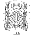
- Figure 3c is a cutaway perspective view of the same embodiment, shown without the shell 5, and illustrating the device for holding the shell in the envelope.
- the mortar shell adapter consists of an envelope 2 of substantially cylindrical shape, prefragmented and comprising at one of its at the ends a rear portion formed by a base 3 surmounted by a median portion 28 to form a sleeve 1.
- the middle portion 28 contains additional charges 26 and a lead-in tube 40.
- a cap 27 provides the sealing between the middle portion 28 and the inner part of the casing 2 where the shell 5 is placed.
- the base 3, the middle part 28 and the casing 2 are integral and are fixed together by any means of joining (gluing, welding, clipping, screwing, ).
- the casing 2 comprises rupture primers 24 to facilitate its fragmentation and its evacuation after the firing of the shell 5.
- the casing 2 must be sufficiently rigid to maintain and guide the shell, but also to be easily fragmentable. It may for example be made of polyamide.
- the casing 2 has openings 25 making it possible to have an identical pressure inside and outside the chamber in order to avoid containment of the propellant gas. Such openings increase the expansion volume C 'of the propulsion gases. To overcome this increase in C ', it is necessary to increase the propulsion energy of the shell. It is therefore imperative to equip the munition with an additional charge 26 which supplements or replaces the initial propellant charge.
- the additional charge 26 is disposed in the base 3 and is initiated by a lead-in tube 40.
- the propellant charge of the shell initially disposed around the shell tail will not be suppressed but supplemented by a propellant charge disposed in the middle portion 28.
- the fins 8 have at their end a tongue 80 ( Figure 3a).
- the casing 2 has at its rear end gills 30 between which are positioned the tongues of the fins, the maintenance of the shell is ensured by the elastic deformation of these gills.
- Such a device for maintaining the shell is particularly advantageous. Indeed, although it is preferentially provided for the gills 30 cooperate with tabs, the maintenance of the shell can also be ensured when the fins do not have a tab.
- the elastic deformation of the gills generates forces substantially perpendicular to the axis of the shell. These efforts are enough to keep the shell in the envelope.
- FIG. 3c also illustrates an exemplary embodiment of the various connections between the elements constituting the socket.
- the connection between the cover 27 and the middle portion 28 is made by tight fitting.
- the casing 2 is secured to the lid 27 by means of plastic rivets 29 of the "fir rivets" type.
- the base 3 is secured to the middle portion 28 by means of a known device, such as a rosette.
- the sleeve ensures the guidance of the empennage at the postage of the projectile (first moments of shooting).
- the casing of the sleeve 1 is fragmented and is therefore for single use.
- the ignition of the additional propellant charges 26 is conventionally initiated by the lead-in tube 4, as explained in connection with FIG. 2.
- the ignition of the additional propellant charges 26 generates propulsion gases which tear the lid 27 and propel the shell.
- a sleeve 1 is formed consisting of a casing 2 of substantially cylindrical shape with an inner diameter substantially equal to the caliber of the shell 5 and whose end intended to be disposed at the level of the cylinder head. weapon is closed by a base 3 having a means 4 for initiating the propellant charge 7 of the shell. A mortar shell 5 is then placed in this socket, by setting the shell by a wedging means 20, a ring 9, or by the envelope 2.
Landscapes
- Engineering & Computer Science (AREA)
- General Engineering & Computer Science (AREA)
- Portable Nailing Machines And Staplers (AREA)
Applications Claiming Priority (1)
| Application Number | Priority Date | Filing Date | Title |
|---|---|---|---|
| FR0503665A FR2884603B1 (fr) | 2005-04-13 | 2005-04-13 | Dispositif d'adaptation d'un obus de mortier dans un canon |
Publications (1)
| Publication Number | Publication Date |
|---|---|
| EP1712873A1 true EP1712873A1 (de) | 2006-10-18 |
Family
ID=35241175
Family Applications (1)
| Application Number | Title | Priority Date | Filing Date |
|---|---|---|---|
| EP06290474A Withdrawn EP1712873A1 (de) | 2005-04-13 | 2006-03-23 | Adapter für ein Mörsergeschoss in einem Geschützlauf |
Country Status (2)
| Country | Link |
|---|---|
| EP (1) | EP1712873A1 (de) |
| FR (1) | FR2884603B1 (de) |
Cited By (6)
| Publication number | Priority date | Publication date | Assignee | Title |
|---|---|---|---|---|
| FR2914991A1 (fr) | 2007-04-11 | 2008-10-17 | Nexter Munitions Sa | Dispositif d'adaptation d'un obus dont la charge propulsive est initiee par percussion pour son utilisation dans une arme dotee de moyens d'initiation electriques |
| FR2915564A1 (fr) | 2007-04-30 | 2008-10-31 | Nexter Munitions Sa | Dispositif electromecanique d'adaptation d'un obus |
| WO2009095540A1 (en) * | 2008-01-31 | 2009-08-06 | Patria Land & Armament Oy | Arrangement for supporting shell into weapon barrel, support element and method |
| WO2009095539A1 (en) * | 2008-01-31 | 2009-08-06 | Patria Land & Armament Oy | Arrangement for supporting mortar shell into breech-loading weapon barrel |
| CN112504008B (zh) * | 2020-11-27 | 2022-07-01 | 江苏科技大学 | 一种多破片同步发射弹托装置及其装配方法 |
| US11656063B2 (en) | 2020-11-12 | 2023-05-23 | General Dynamics OTS—Canada, Inc. | Reduced-energy cartridge with exterior sealing member for fluted chamber |
Citations (7)
| Publication number | Priority date | Publication date | Assignee | Title |
|---|---|---|---|---|
| US2872864A (en) * | 1952-01-08 | 1959-02-10 | Gladeon M Barnes | Center-guide for fin-stabilized fixed round ammunition |
| GB924062A (en) * | 1960-10-25 | 1963-04-24 | Energa | Improvements in or relating to finned projectiles |
| FR1334281A (fr) * | 1962-03-03 | 1963-08-02 | Dynamit Nobel Ag | Projectile d'exercice pour lance-grenades |
| FR1404877A (fr) * | 1963-08-13 | 1965-07-02 | Dynamit Nobel Ag | Munition d'exercice pour lance-mines |
| EP0759146A1 (de) | 1994-05-10 | 1997-02-26 | Bofors LIAB AB | Granate für waffen mit glattem lauf |
| EP0954742A1 (de) | 1997-01-24 | 1999-11-10 | Patria Vammas OY | Vorrichtung zur unterstützung eines geschosses im rohr |
| WO2004003454A1 (en) | 2002-06-27 | 2004-01-08 | Patria Vammas Oy | Arrangement for supporting a mortar shell into barrel of weapon and a method for attaching a support member to a mortar shell |
-
2005
- 2005-04-13 FR FR0503665A patent/FR2884603B1/fr not_active Expired - Fee Related
-
2006
- 2006-03-23 EP EP06290474A patent/EP1712873A1/de not_active Withdrawn
Patent Citations (7)
| Publication number | Priority date | Publication date | Assignee | Title |
|---|---|---|---|---|
| US2872864A (en) * | 1952-01-08 | 1959-02-10 | Gladeon M Barnes | Center-guide for fin-stabilized fixed round ammunition |
| GB924062A (en) * | 1960-10-25 | 1963-04-24 | Energa | Improvements in or relating to finned projectiles |
| FR1334281A (fr) * | 1962-03-03 | 1963-08-02 | Dynamit Nobel Ag | Projectile d'exercice pour lance-grenades |
| FR1404877A (fr) * | 1963-08-13 | 1965-07-02 | Dynamit Nobel Ag | Munition d'exercice pour lance-mines |
| EP0759146A1 (de) | 1994-05-10 | 1997-02-26 | Bofors LIAB AB | Granate für waffen mit glattem lauf |
| EP0954742A1 (de) | 1997-01-24 | 1999-11-10 | Patria Vammas OY | Vorrichtung zur unterstützung eines geschosses im rohr |
| WO2004003454A1 (en) | 2002-06-27 | 2004-01-08 | Patria Vammas Oy | Arrangement for supporting a mortar shell into barrel of weapon and a method for attaching a support member to a mortar shell |
Cited By (11)
| Publication number | Priority date | Publication date | Assignee | Title |
|---|---|---|---|---|
| FR2914991A1 (fr) | 2007-04-11 | 2008-10-17 | Nexter Munitions Sa | Dispositif d'adaptation d'un obus dont la charge propulsive est initiee par percussion pour son utilisation dans une arme dotee de moyens d'initiation electriques |
| FR2915564A1 (fr) | 2007-04-30 | 2008-10-31 | Nexter Munitions Sa | Dispositif electromecanique d'adaptation d'un obus |
| WO2009095540A1 (en) * | 2008-01-31 | 2009-08-06 | Patria Land & Armament Oy | Arrangement for supporting shell into weapon barrel, support element and method |
| WO2009095539A1 (en) * | 2008-01-31 | 2009-08-06 | Patria Land & Armament Oy | Arrangement for supporting mortar shell into breech-loading weapon barrel |
| JP2011511252A (ja) * | 2008-01-31 | 2011-04-07 | パトリア、ランド、アンド、アーマメント、オサケ、ユキチュア | 弾丸を武器の砲身内に支持するための装置、支持要素および方法 |
| JP2011511251A (ja) * | 2008-01-31 | 2011-04-07 | パトリア、ランド、アンド、アーマメント、オサケ、ユキチュア | 後装式兵器の砲身内で迫撃砲弾を支持するための装置 |
| US8550002B2 (en) | 2008-01-31 | 2013-10-08 | Patria Land Systems Oy | Arrangement for supporting mortar shell into breech-loading weapon barrel |
| US8590452B2 (en) | 2008-01-31 | 2013-11-26 | Patria Land Systems Oy | Arrangement for supporting shell into weapon barrel, support element and method |
| AU2009208919B2 (en) * | 2008-01-31 | 2014-01-09 | Patria Land & Armament Oy | Arrangement for supporting mortar shell into breech-loading weapon barrel |
| US11656063B2 (en) | 2020-11-12 | 2023-05-23 | General Dynamics OTS—Canada, Inc. | Reduced-energy cartridge with exterior sealing member for fluted chamber |
| CN112504008B (zh) * | 2020-11-27 | 2022-07-01 | 江苏科技大学 | 一种多破片同步发射弹托装置及其装配方法 |
Also Published As
| Publication number | Publication date |
|---|---|
| FR2884603B1 (fr) | 2010-10-08 |
| FR2884603A1 (fr) | 2006-10-20 |
Similar Documents
| Publication | Publication Date | Title |
|---|---|---|
| EP0905473B1 (de) | Grosskalibriges und weitreichendes Artilleriegeschoss | |
| FR2529319A1 (fr) | Munition comportant une charge propulsive et un projectile stabilise par ailettes | |
| CH634142A5 (fr) | Mecanisme de lancement d'un projectile sous-calibre. | |
| EP0307307B1 (de) | Verbindungsring zwischen Geschoss und Geschosshülse | |
| FR2644880A1 (fr) | Systeme d'ouverture d'un empennage deployant pour projectile | |
| EP0737298B1 (de) | Flintenlaufgeschoss mit teleskopartigem pfeil mit einem an einem launcher teilnehmenden subgeschoss | |
| EP1181498B1 (de) | Anzündrohr für artilleriemunition | |
| EP0048644B1 (de) | Geschoss mit Leitflossen in Gestalt eines Pfeiles | |
| EP0659264B1 (de) | Vorrichtung zur abdichtung der teribgase bei artilleriegeschossen | |
| BE1016438A5 (fr) | Dispositif de tir. | |
| EP1712873A1 (de) | Adapter für ein Mörsergeschoss in einem Geschützlauf | |
| EP0279715B1 (de) | Feuerwaffe für hülsenlose Munition und Munition für eine solche Waffe | |
| EP0728293B1 (de) | Flintenlaufgeschoss mit doppeleindringung und reduzierter schussweite | |
| FR2650388A1 (fr) | Perfectionnements apportes aux munitions destinees a etre tirees par une arme a canon lisse | |
| FR2719373A1 (fr) | Dispositif de propulsion à portées variables pour grenade anti-émeutes. | |
| EP0664433B1 (de) | Panzerabwehrgeschoss und eine mit einem solchen Geschoss versehene Munition | |
| FR2927417A1 (fr) | Obus de dispersion de projectiles | |
| EP0486077A1 (de) | Gewehrgranate | |
| FR2698163A1 (fr) | Projectile de perforation et munition équipée d'un tel projectile. | |
| CA2176029C (fr) | Balle de chasse a double penetration et a portee reduite | |
| FR2914991A1 (fr) | Dispositif d'adaptation d'un obus dont la charge propulsive est initiee par percussion pour son utilisation dans une arme dotee de moyens d'initiation electriques | |
| BE708180A (de) | ||
| FR2732456A1 (fr) | Amorces de rupture de ceinture pour projectile fleche | |
| FR3013114A1 (fr) | Dispositif de propulsion pour une munition utilisable avec un lanceur | |
| EP1023573A1 (de) | Treibkäfig mit verbesserter gasabdichtung für submunitionskörper |
Legal Events
| Date | Code | Title | Description |
|---|---|---|---|
| PUAI | Public reference made under article 153(3) epc to a published international application that has entered the european phase |
Free format text: ORIGINAL CODE: 0009012 |
|
| AK | Designated contracting states |
Kind code of ref document: A1 Designated state(s): AT BE BG CH CY CZ DE DK EE ES FI FR GB GR HU IE IS IT LI LT LU LV MC NL PL PT RO SE SI SK TR |
|
| AX | Request for extension of the european patent |
Extension state: AL BA HR MK YU |
|
| RAP1 | Party data changed (applicant data changed or rights of an application transferred) |
Owner name: NEXTER MUNITIONS |
|
| 17P | Request for examination filed |
Effective date: 20070413 |
|
| 17Q | First examination report despatched |
Effective date: 20070529 |
|
| AKX | Designation fees paid |
Designated state(s): AT BE BG CH CY CZ DE DK EE ES FI FR GB GR HU IE IS IT LI LT LU LV MC NL PL PT RO SE SI SK TR |
|
| GRAP | Despatch of communication of intention to grant a patent |
Free format text: ORIGINAL CODE: EPIDOSNIGR1 |
|
| STAA | Information on the status of an ep patent application or granted ep patent |
Free format text: STATUS: THE APPLICATION HAS BEEN WITHDRAWN |
|
| 18W | Application withdrawn |
Effective date: 20091222 |