EP1712894B1 - Compteur de particules pour particules étrangères dans un flux liquide - Google Patents
Compteur de particules pour particules étrangères dans un flux liquide Download PDFInfo
- Publication number
- EP1712894B1 EP1712894B1 EP06111901A EP06111901A EP1712894B1 EP 1712894 B1 EP1712894 B1 EP 1712894B1 EP 06111901 A EP06111901 A EP 06111901A EP 06111901 A EP06111901 A EP 06111901A EP 1712894 B1 EP1712894 B1 EP 1712894B1
- Authority
- EP
- European Patent Office
- Prior art keywords
- particle counter
- piston
- cylinder
- measuring
- pressure
- Prior art date
- Legal status (The legal status is an assumption and is not a legal conclusion. Google has not performed a legal analysis and makes no representation as to the accuracy of the status listed.)
- Ceased
Links
- 239000002245 particle Substances 0.000 title claims description 35
- 239000007788 liquid Substances 0.000 title description 24
- 239000012530 fluid Substances 0.000 claims description 16
- 230000004888 barrier function Effects 0.000 claims description 6
- 238000010438 heat treatment Methods 0.000 claims description 6
- 238000007789 sealing Methods 0.000 claims description 5
- 238000000034 method Methods 0.000 claims description 4
- 238000001816 cooling Methods 0.000 claims description 3
- 238000011156 evaluation Methods 0.000 claims description 3
- 238000011144 upstream manufacturing Methods 0.000 claims description 3
- 238000005259 measurement Methods 0.000 description 8
- 238000012937 correction Methods 0.000 description 4
- 230000001419 dependent effect Effects 0.000 description 3
- 238000012544 monitoring process Methods 0.000 description 3
- 238000012360 testing method Methods 0.000 description 3
- 238000011109 contamination Methods 0.000 description 2
- 239000010720 hydraulic oil Substances 0.000 description 2
- 230000005540 biological transmission Effects 0.000 description 1
- 230000006835 compression Effects 0.000 description 1
- 238000007906 compression Methods 0.000 description 1
- 238000013461 design Methods 0.000 description 1
- 239000000428 dust Substances 0.000 description 1
- 239000003921 oil Substances 0.000 description 1
Images
Classifications
-
- G—PHYSICS
- G01—MEASURING; TESTING
- G01N—INVESTIGATING OR ANALYSING MATERIALS BY DETERMINING THEIR CHEMICAL OR PHYSICAL PROPERTIES
- G01N15/00—Investigating characteristics of particles; Investigating permeability, pore-volume or surface-area of porous materials
- G01N15/10—Investigating individual particles
- G01N15/14—Optical investigation techniques, e.g. flow cytometry
-
- G—PHYSICS
- G05—CONTROLLING; REGULATING
- G05D—SYSTEMS FOR CONTROLLING OR REGULATING NON-ELECTRIC VARIABLES
- G05D16/00—Control of fluid pressure
- G05D16/04—Control of fluid pressure without auxiliary power
- G05D16/10—Control of fluid pressure without auxiliary power the sensing element being a piston or plunger
-
- G—PHYSICS
- G01—MEASURING; TESTING
- G01N—INVESTIGATING OR ANALYSING MATERIALS BY DETERMINING THEIR CHEMICAL OR PHYSICAL PROPERTIES
- G01N15/00—Investigating characteristics of particles; Investigating permeability, pore-volume or surface-area of porous materials
- G01N15/10—Investigating individual particles
- G01N15/14—Optical investigation techniques, e.g. flow cytometry
- G01N15/1434—Optical arrangements
-
- G—PHYSICS
- G01—MEASURING; TESTING
- G01N—INVESTIGATING OR ANALYSING MATERIALS BY DETERMINING THEIR CHEMICAL OR PHYSICAL PROPERTIES
- G01N1/00—Sampling; Preparing specimens for investigation
- G01N1/02—Devices for withdrawing samples
- G01N1/10—Devices for withdrawing samples in the liquid or fluent state
- G01N1/20—Devices for withdrawing samples in the liquid or fluent state for flowing or falling materials
- G01N1/2035—Devices for withdrawing samples in the liquid or fluent state for flowing or falling materials by deviating part of a fluid stream, e.g. by drawing-off or tapping
- G01N2001/2064—Devices for withdrawing samples in the liquid or fluent state for flowing or falling materials by deviating part of a fluid stream, e.g. by drawing-off or tapping using a by-pass loop
-
- G—PHYSICS
- G01—MEASURING; TESTING
- G01N—INVESTIGATING OR ANALYSING MATERIALS BY DETERMINING THEIR CHEMICAL OR PHYSICAL PROPERTIES
- G01N15/00—Investigating characteristics of particles; Investigating permeability, pore-volume or surface-area of porous materials
- G01N15/10—Investigating individual particles
- G01N15/14—Optical investigation techniques, e.g. flow cytometry
- G01N2015/1486—Counting the particles
-
- G—PHYSICS
- G01—MEASURING; TESTING
- G01N—INVESTIGATING OR ANALYSING MATERIALS BY DETERMINING THEIR CHEMICAL OR PHYSICAL PROPERTIES
- G01N15/00—Investigating characteristics of particles; Investigating permeability, pore-volume or surface-area of porous materials
- G01N15/10—Investigating individual particles
- G01N15/14—Optical investigation techniques, e.g. flow cytometry
- G01N2015/1493—Particle size
-
- G—PHYSICS
- G01—MEASURING; TESTING
- G01N—INVESTIGATING OR ANALYSING MATERIALS BY DETERMINING THEIR CHEMICAL OR PHYSICAL PROPERTIES
- G01N21/00—Investigating or analysing materials by the use of optical means, i.e. using sub-millimetre waves, infrared, visible or ultraviolet light
- G01N21/84—Systems specially adapted for particular applications
- G01N21/85—Investigating moving fluids or granular solids
- G01N2021/8557—Special shaping of flow, e.g. using a by-pass line, jet flow, curtain flow
-
- G—PHYSICS
- G01—MEASURING; TESTING
- G01N—INVESTIGATING OR ANALYSING MATERIALS BY DETERMINING THEIR CHEMICAL OR PHYSICAL PROPERTIES
- G01N21/00—Investigating or analysing materials by the use of optical means, i.e. using sub-millimetre waves, infrared, visible or ultraviolet light
- G01N21/17—Systems in which incident light is modified in accordance with the properties of the material investigated
- G01N21/47—Scattering, i.e. diffuse reflection
- G01N21/49—Scattering, i.e. diffuse reflection within a body or fluid
- G01N21/53—Scattering, i.e. diffuse reflection within a body or fluid within a flowing fluid, e.g. smoke
- G01N21/534—Scattering, i.e. diffuse reflection within a body or fluid within a flowing fluid, e.g. smoke by measuring transmission alone, i.e. determining opacity
Definitions
- the invention relates to a particle counter operating according to the dimming or light blockade method for counting foreign particles in a liquid flow, in particular in a hydraulic fluid flow, according to the preamble of patent claim 1.
- Such a particle counter is off DE 89 12 584 U1 known.
- a complex volume flow control device is required to achieve a constant flow velocity within the measuring channel.
- a generic measuring device is still known from DE 20 62 698 A1 and described in the non-prepublished WO 2005/038434 A1 , With the particle counters of these devices, only constant volume flows can be checked with respect to their particle content with a volume flow to be observed defined, wherein the constant flow rate must be achieved by constant-flow medium.
- the invention is concerned with the problem of creating a particle counter which is as simple as possible and yet operates with high measuring accuracy.
- a particle counter should be part of a working device through which liquid to be measured flows.
- the liquid should in particular be hydraulic oil of a hydraulically operating device, the degree of contamination of which is determined stationarily with such a particle counter can be and in any short time intervals. It should also be possible to be able to recognize different particle sizes separately. In particular, a continuous monitoring of the degree of contamination of such a hydraulic fluid with a particle counter according to the invention should be possible.
- the volume flow per measuring time must be known.
- the size of a volume flow is known, for example, if it can be set to a specific value and kept constant.
- a constant volume flow in turn, necessarily results in a geometrically constant flow channel at a constant predetermined pressure gradient along this flow channel.
- an additional prerequisite is that the flowing liquid has a constant viscosity value. Since the viscosity value of a liquid is usually temperature-dependent, in particular for a hydraulic fluid, it sets at a constant pressure Pressure gradient a constant volume flow Temperature equality ahead.
- a heating or cooling device for influencing the temperature of the liquid stream to be measured.
- the cooling or heating device is designed so that there is a temperature for performing a measurement, which is preferably outside a possible operating temperature. This ensures that, regardless of current operating temperatures, a measurement can always be carried out at the same measuring temperature outside an operating temperature.
- a heating device is used by which a measuring, that is to say an active operation of a particle counter, always lies at a temperature above the operating temperature of the liquid to be measured with regard to its particle loading.
- the device according to the invention can also be advantageously used in particular for measuring and monitoring the degree of soiling of transmission oil.
- the influence of a changing viscosity on a constant liquid flow to be generated by a pressure difference in a measuring channel is eliminated by a specific temperature control of the measuring liquid flow.
- Another possibility (which is not part of the invention) of avoiding a changing viscosity as a disturbance factor for the measurement consists of detecting the temperature of the measuring liquid in the measuring channel and the respective measured values of the particle counting by an electronically stored, in particular experimentally dependent to correct the correction curve determined for different measuring fluid temperatures. Correcting here means that viscosity-related changes in the volume flow of the measuring liquid flow are neutralized according to an electronic correction memory, wherein the correction memory is to be created with reference in each case to a liquid to be measured.
- different correction values can be stored for different liquids and retrieved as needed.
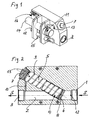
- the particle counter is formed in a, in a liquid, in particular hydraulic fluid line, usable measuring device.
- Incoming liquid flows in a main flow into a main flow channel opening 1 of a main flow channel 2 and leaves this main flow channel 2 through a main flow channel outlet opening 3.
- a spring-loaded throttle valve 4 is integrated in the main flow channel 2.
- This throttle valve 4 comprises a, in a cylinder 5 slidably mounted piston 6.
- the cylinder 5 is provided at one end with a closed bottom 7 in the form of a sealing plug and the other end open. From this open end of the cylinder 5, the piston 6 can penetrate into the flow path of the main flow channel 2 and completely close this path.
- the piston 6 bears against a valve seat 8 arranged correspondingly in the main flow channel 2. In the direction of a closed position on the valve seat 8, the piston 6 is acted upon by a force applied in the interior of the cylinder 5 spring 9.
- the spring 9 is supported at one end on the piston 6 and the other end on the bottom 7 of the cylinder.
- the axis of the cylinder 5, along which the piston 6 can move, is inclined relative to the longitudinal axis of the main flow channel 2, that liquid flowing from the inlet opening 1 into the main flow channel 2 can act on the end face of the piston 6 in a throttle valve opening manner.
- This opening force counteracts the force of the spring 9, which is designed here as a compression spring.
- the flow direction of the main flow channel 2 is marked with flow arrows S.
- the main flow channel 2 Downstream of the piston 6 of the throttle valve 4, the main flow channel 2 is pressure-equalizing connected via a connecting channel 10 in, for example, the shape of a throttle channel with the interior of the cylinder 5.
- the light barrier measurement according to the invention by the dimming or light blockade method which is known per se in the prior art is carried out in a measuring channel 11, which is designed as a bypass bridging the throttle valve 4 to the main flow channel 2.
- a measuring channel 11 which is designed as a bypass bridging the throttle valve 4 to the main flow channel 2.
- the connection openings of this measuring channel are shown, wherein the measuring channel inlet located upstream of the throttle valve 4 is denoted by 12 and the measuring channel outlet by 13.
- the measuring channel 11 is associated with a known per se in such a particle counter sensor device 14.
- this measuring channel 11 penetrates a heating device 15 in its supply region.
- the liquid flowing through is heated to a predetermined temperature value outside the possible operating temperatures, whereby this liquid causes the sensor device 14 always flows through an equal, constant temperature.
- the electronic part of the particle counter is in the Fig. 1 indicated by 16.
- This electronic part 16 comprises the devices for, for example, a telemetric remote display of the measured values from the sensor device 14, including their measured values, which are evaluated in particular in this electronic part.
- the display of the evaluated measured values can be done digitally or analogously at any desired location in a manner known per se.
- a telemetric remote display is particularly interesting when using a particle counter according to the invention for monitoring a hydraulic oil circuit in an offshore wind turbine, for example.
- the throttle valve 4 may be designed for example by a corresponding spring 9 for a constant pressure drop of 0.5 bar within the main flow channel 2.
- the measuring channel volume flow defined hereby and by the size of the flow cross-section of the measuring channel 11 can be, for example, 50 ml / min.
- a single-channel laser device can be used as a sensor device 14.
- the achievable measured values and their evaluation possibilities correspond to the well-known in generic particle counters state of the art, which is why this need not be discussed in detail in the description of the present invention.
- a calibration of the measuring device with a test liquid adapted to the liquid to be measured is required in each case.
- Each test fluid is mixed with a precisely defined test dust.
- the measuring device With the measuring device according to the invention, it is possible to determine the particle size in a measuring window, so that the evaluation of the measurement result can be switched to preset classes of particle sizes by simply switching the measuring device.
- the switching can be done automatically by the electronics, so that a principle one-channel measuring device can work by repeatedly switching to another class such as a multi-channel measuring device. This is a special feature of the present invention.
- a measurement accuracy of at least about +/- 20% can be ensured without further ado.
Landscapes
- Physics & Mathematics (AREA)
- Chemical & Material Sciences (AREA)
- General Physics & Mathematics (AREA)
- Life Sciences & Earth Sciences (AREA)
- Biochemistry (AREA)
- Engineering & Computer Science (AREA)
- Dispersion Chemistry (AREA)
- Health & Medical Sciences (AREA)
- Fluid Mechanics (AREA)
- Analytical Chemistry (AREA)
- Automation & Control Theory (AREA)
- General Health & Medical Sciences (AREA)
- Immunology (AREA)
- Pathology (AREA)
- Fluid-Pressure Circuits (AREA)
- Measuring Volume Flow (AREA)
- Measuring Fluid Pressure (AREA)
- Investigating Or Analyzing Materials Using Thermal Means (AREA)
Claims (4)
- Compteur de particules fonctionnant selon le procédé d'obscurcissement, resp. de blocage de lumière pour compter des particules étrangères dans un courant de liquide, notamment dans un courant de liquide hydraulique, comportant une cellule de détection photoélectrique, dont le rayon lumineux traverse un canal de mesure à travers lequel s'écoule un courant partiel de dérivation du courant de liquide, et comportant un module électronique d'évaluation branché en aval du récepteur de la cellule de détection photoélectrique,
caractérisé par les caractéristiques- le compteur de particules comprend un dispositif de régulation de pression (4) agissant sur le courant de liquide, lequel impose à la zone située entre le débit entrant et le débit sortant du canal de mesure (11), renfermant la cellule de détection photoélectrique, une différence de pression prescrite définie, indépendante des propriétés d'écoulement du courant principal de liquide quand le liquide s'écoule,- le compteur de particules comprend un dispositif de chauffage ou de refroidissement (15) pour tempérer le courant partiel traversant le canal de mesure (11) à une valeur de température prescrite,- le dispositif de régulation de pression (4) est conçu comme une soupape d'étranglement comportant un corps d'obturation sollicité par une force de ressort, situé à l'intérieur du trajet d'étranglement de la soupape, dont la position d'ouverture, resp. de fermeture est dépendante de la différence de pression suscitée sur celui-ci du côté flux entrant et du côté flux sortant, moyennant quoi la force de ressort chargeant le corps d'obturation (6) est dirigée à l'encontre de la pression dynamique exercée sur le corps d'obturation (6) de manière à favoriser l'étranglement. - Compteur de particules selon la revendication 1,
caractérisé par les caractéristiques,- le corps d'obturation est un piston (6) positionné de manière déplaçable dans un cylindre (5),- le cylindre (5) est délimité à une extrémité par un fond de cylindre fixe (7) et à une autre extrémité par le piston déplaçable (6),- le piston (6) plonge par une portion d'extrémité dépassant hors du cylindre (5) dans le courant de liquide,- le piston (6) est chargé par la force d'un ressort (9) dans la direction où il quitte le cylindre (5),- la force de ressort est dirigée à l'encontre d'une force agissant de manière à ouvrir l'obturation sur le piston à travers le flux entrant de liquide,- l'espace du cylindre (5) occupé par le piston (6) est relié par un canal de liaison (10) au côté de flux sortant du piston (6) à l'intérieur du courant de liquide,- la différence de pression constante quand le liquide s'écoule suscitée sur le canal de mesure (11) est déterminée par la force du ressort (9) sollicitant le piston (6). - Compteur de particules selon la revendication 1 ou 2,
caractérisé en ce que
il comprend des moyens permettant un affichage à distance des valeurs de mesure. - Compteur de particules selon la revendication 3,
caractérisé en ce que
il comprend des moyens permettant un affichage à distance télémétrique des valeurs de mesure.
Applications Claiming Priority (1)
| Application Number | Priority Date | Filing Date | Title |
|---|---|---|---|
| DE102005016761A DE102005016761A1 (de) | 2005-04-11 | 2005-04-11 | Partikelzähler für Fremdpartikel in einem Flüssigkeitsstrom |
Publications (2)
| Publication Number | Publication Date |
|---|---|
| EP1712894A1 EP1712894A1 (fr) | 2006-10-18 |
| EP1712894B1 true EP1712894B1 (fr) | 2009-09-09 |
Family
ID=36297336
Family Applications (1)
| Application Number | Title | Priority Date | Filing Date |
|---|---|---|---|
| EP06111901A Ceased EP1712894B1 (fr) | 2005-04-11 | 2006-03-29 | Compteur de particules pour particules étrangères dans un flux liquide |
Country Status (3)
| Country | Link |
|---|---|
| US (1) | US7382452B2 (fr) |
| EP (1) | EP1712894B1 (fr) |
| DE (2) | DE102005016761A1 (fr) |
Families Citing this family (2)
| Publication number | Priority date | Publication date | Assignee | Title |
|---|---|---|---|---|
| CN101583870A (zh) * | 2006-12-18 | 2009-11-18 | 空中客车法国公司 | 监控流动液压流体中颗粒污染的装置和方法 |
| ES2646732B2 (es) * | 2017-03-29 | 2018-07-30 | Universidad De Cantabria | Dispositivo portátil para la monitorización, ensayo, incorporación de aditivos y control de tuberías, sus materiales y fluidos |
Family Cites Families (13)
| Publication number | Priority date | Publication date | Assignee | Title |
|---|---|---|---|---|
| US3632210A (en) * | 1969-06-19 | 1972-01-04 | Environment One Corp | Variable rate continuous flow condensation nuclei meter having adjustable expansion period and improved gain |
| DE2062698A1 (de) * | 1970-12-19 | 1972-06-29 | Teves Gmbh Alfred | Verfahren und Vorrichtung zur Ermittlung des Verschleißes an Hydraulikaggregaten |
| GB1471527A (en) * | 1973-06-14 | 1977-04-27 | Coulter Electronics Ld | On-line system for monitoring particles in fluids |
| DE8912584U1 (de) * | 1989-10-24 | 1989-12-07 | Hydac Technology GmbH, 6603 Sulzbach | Partikelzähler |
| DE4110231C2 (de) * | 1991-03-28 | 1995-01-05 | Knecht Filterwerke Gmbh | Meßeinrichtung zum Bestimmen des Schmutzpartikelanteils von Flüssigkeiten |
| US5118959A (en) * | 1991-05-03 | 1992-06-02 | Tsi Incorporated | Water separation system for condensation particle counter |
| US5379791A (en) * | 1993-09-03 | 1995-01-10 | Christopher; John F. | Dual-head flow controller and method |
| DE19627587C2 (de) * | 1996-07-09 | 1999-02-04 | Hydac Filtertechnik Gmbh | Vorrichtung zur Überwachung von Gebrauchseigenschaften von Fluiden, insbesondere von Druckflüssigkeiten in fluidtechnischen Anlagen |
| DE19735066C1 (de) * | 1997-08-13 | 1999-01-28 | Hydac Filtertechnik Gmbh | Auswerteverfahren für einen Partikelzähler und Vorrichtung zum Durchführen des Verfahrens |
| DE10127021C1 (de) * | 2001-06-01 | 2003-02-20 | Hydac Filtertechnik Gmbh | Vorrichtung zur Gewinnung einer Verschmutzungsanzeige für Filterelemente in hydraulischen Systemen |
| US6912479B2 (en) * | 2002-12-26 | 2005-06-28 | Volvo Construction Equipment Holding Sweden Ab | Heavy equipment having oil pollution degree diagnosing function, and oil pollution degree measuring system on network using the same, and operation method |
| DE10343457C5 (de) * | 2003-09-19 | 2012-01-12 | Hydac Filtertechnik Gmbh | Vorrichtung zur Partikelmessung |
| KR100614101B1 (ko) * | 2005-09-15 | 2006-08-22 | 한국과학기술연구원 | 입자 계수기 |
-
2005
- 2005-04-11 DE DE102005016761A patent/DE102005016761A1/de not_active Withdrawn
-
2006
- 2006-03-29 DE DE502006004770T patent/DE502006004770D1/de not_active Expired - Lifetime
- 2006-03-29 EP EP06111901A patent/EP1712894B1/fr not_active Ceased
- 2006-04-11 US US11/402,073 patent/US7382452B2/en not_active Expired - Fee Related
Also Published As
| Publication number | Publication date |
|---|---|
| EP1712894A1 (fr) | 2006-10-18 |
| DE102005016761A1 (de) | 2006-10-12 |
| US20060227926A1 (en) | 2006-10-12 |
| DE502006004770D1 (de) | 2009-10-22 |
| US7382452B2 (en) | 2008-06-03 |
Similar Documents
| Publication | Publication Date | Title |
|---|---|---|
| DE2521952C3 (de) | Durchflußmesser | |
| EP0797080A2 (fr) | Vanne de réglage d'écoulement avec débitmètre | |
| DE202008003055U1 (de) | Druckminderer-Filter Anordnung mit Leckageschutz | |
| EP3225315A1 (fr) | Procede et dispositif de dosage destine au dosage reglable en pression d'un produit liquide ou pateux | |
| DE102008062521A1 (de) | Strömungssensor für fluide Medien | |
| DE202020003961U1 (de) | Leckerfassungsvorrichtung zur Erfassung eines Lecks in einem ein Fluid führenden System | |
| DE10038874C2 (de) | Ventil zum Regulieren und Messen des Strömungsdurchsatzes eines Fluids | |
| EP1712894B1 (fr) | Compteur de particules pour particules étrangères dans un flux liquide | |
| EP0777109A2 (fr) | Dispositif de détermination de la force d'un courant volumétrique gazeux | |
| EP1904812A1 (fr) | Sonde de pitot | |
| EP0948282B1 (fr) | Accessoire pour aspirateur | |
| DE202014101518U1 (de) | Vorrichtung für die Feldflussfraktionierung | |
| WO2010108572A1 (fr) | Tampon de quenouille en céramique réfractaire | |
| DE10259395A1 (de) | Anschlussstück für Fluidleitungen | |
| DE2021782C3 (de) | Volumenmeßvornchtung | |
| DE102005006478B4 (de) | Verteilerventil | |
| WO2009080353A2 (fr) | Dispositif de surveillance pour la surveillance d'un fluide | |
| EP1505372A1 (fr) | Garniture de mesure et de réglage du débit d'un fluide hydraulique dans un tube | |
| EP0294542B1 (fr) | Soupape | |
| DE102006047880B4 (de) | Durchflußeinstellventil | |
| AT11330U1 (de) | Anordnung mit zumindest einer durchflussmesseinrichtung für fluide | |
| DE19539597A1 (de) | Strömungsmeßgerät | |
| DE2423496A1 (de) | Hydraulische drosselstelle | |
| EP2833038A1 (fr) | Soupape pour liquides sensibles aux champs et installation hydraulique dotée d'une telle soupape | |
| DE102005027372B4 (de) | Verteilerventil |
Legal Events
| Date | Code | Title | Description |
|---|---|---|---|
| PUAI | Public reference made under article 153(3) epc to a published international application that has entered the european phase |
Free format text: ORIGINAL CODE: 0009012 |
|
| 17P | Request for examination filed |
Effective date: 20060902 |
|
| AK | Designated contracting states |
Kind code of ref document: A1 Designated state(s): AT BE BG CH CY CZ DE DK EE ES FI FR GB GR HU IE IS IT LI LT LU LV MC NL PL PT RO SE SI SK TR |
|
| AX | Request for extension of the european patent |
Extension state: AL BA HR MK YU |
|
| AKX | Designation fees paid |
Designated state(s): DE FR GB |
|
| GRAP | Despatch of communication of intention to grant a patent |
Free format text: ORIGINAL CODE: EPIDOSNIGR1 |
|
| GRAS | Grant fee paid |
Free format text: ORIGINAL CODE: EPIDOSNIGR3 |
|
| GRAA | (expected) grant |
Free format text: ORIGINAL CODE: 0009210 |
|
| AK | Designated contracting states |
Kind code of ref document: B1 Designated state(s): DE FR GB |
|
| REG | Reference to a national code |
Ref country code: GB Ref legal event code: FG4D Free format text: NOT ENGLISH |
|
| REF | Corresponds to: |
Ref document number: 502006004770 Country of ref document: DE Date of ref document: 20091022 Kind code of ref document: P |
|
| PLBE | No opposition filed within time limit |
Free format text: ORIGINAL CODE: 0009261 |
|
| STAA | Information on the status of an ep patent application or granted ep patent |
Free format text: STATUS: NO OPPOSITION FILED WITHIN TIME LIMIT |
|
| 26N | No opposition filed |
Effective date: 20100610 |
|
| REG | Reference to a national code |
Ref country code: FR Ref legal event code: PLFP Year of fee payment: 11 |
|
| REG | Reference to a national code |
Ref country code: DE Ref legal event code: R082 Ref document number: 502006004770 Country of ref document: DE Representative=s name: BRP RENAUD UND PARTNER MBB RECHTSANWAELTE PATE, DE Ref country code: DE Ref legal event code: R082 Ref document number: 502006004770 Country of ref document: DE Representative=s name: BRP RENAUD UND PARTNER MBB, DE Ref country code: DE Ref legal event code: R081 Ref document number: 502006004770 Country of ref document: DE Owner name: FILTRATION GROUP GMBH, DE Free format text: FORMER OWNER: MAHLE INTERNATIONAL GMBH, 70376 STUTTGART, DE Ref country code: DE Ref legal event code: R081 Ref document number: 502006004770 Country of ref document: DE Owner name: MAHLE INDUSTRIEFILTRATION GMBH, DE Free format text: FORMER OWNER: MAHLE INTERNATIONAL GMBH, 70376 STUTTGART, DE |
|
| REG | Reference to a national code |
Ref country code: FR Ref legal event code: PLFP Year of fee payment: 12 |
|
| REG | Reference to a national code |
Ref country code: GB Ref legal event code: 732E Free format text: REGISTERED BETWEEN 20170331 AND 20170405 |
|
| REG | Reference to a national code |
Ref country code: FR Ref legal event code: TP Owner name: MAHLE INTERNATIONAL GMBH, DE Effective date: 20170531 |
|
| REG | Reference to a national code |
Ref country code: DE Ref legal event code: R082 Ref document number: 502006004770 Country of ref document: DE Representative=s name: BRP RENAUD UND PARTNER MBB RECHTSANWAELTE PATE, DE Ref country code: DE Ref legal event code: R081 Ref document number: 502006004770 Country of ref document: DE Owner name: FILTRATION GROUP GMBH, DE Free format text: FORMER OWNER: MAHLE INDUSTRIEFILTRATION GMBH, 74613 OEHRINGEN, DE |
|
| REG | Reference to a national code |
Ref country code: FR Ref legal event code: PLFP Year of fee payment: 13 |
|
| REG | Reference to a national code |
Ref country code: FR Ref legal event code: CD Owner name: FILTRATION GROUP GMBH, DE Effective date: 20180423 |
|
| PGFP | Annual fee paid to national office [announced via postgrant information from national office to epo] |
Ref country code: DE Payment date: 20180530 Year of fee payment: 13 |
|
| PGFP | Annual fee paid to national office [announced via postgrant information from national office to epo] |
Ref country code: GB Payment date: 20190327 Year of fee payment: 14 |
|
| REG | Reference to a national code |
Ref country code: DE Ref legal event code: R119 Ref document number: 502006004770 Country of ref document: DE |
|
| PGFP | Annual fee paid to national office [announced via postgrant information from national office to epo] |
Ref country code: FR Payment date: 20190903 Year of fee payment: 14 |
|
| PG25 | Lapsed in a contracting state [announced via postgrant information from national office to epo] |
Ref country code: DE Free format text: LAPSE BECAUSE OF NON-PAYMENT OF DUE FEES Effective date: 20191001 |
|
| PG25 | Lapsed in a contracting state [announced via postgrant information from national office to epo] |
Ref country code: FR Free format text: LAPSE BECAUSE OF NON-PAYMENT OF DUE FEES Effective date: 20200331 |
|
| GBPC | Gb: european patent ceased through non-payment of renewal fee |
Effective date: 20200329 |
|
| PG25 | Lapsed in a contracting state [announced via postgrant information from national office to epo] |
Ref country code: GB Free format text: LAPSE BECAUSE OF NON-PAYMENT OF DUE FEES Effective date: 20200329 |