EP1714123B1 - Appareil concu pour detecter une position et/ou un couple - Google Patents
Appareil concu pour detecter une position et/ou un couple Download PDFInfo
- Publication number
- EP1714123B1 EP1714123B1 EP04778176.0A EP04778176A EP1714123B1 EP 1714123 B1 EP1714123 B1 EP 1714123B1 EP 04778176 A EP04778176 A EP 04778176A EP 1714123 B1 EP1714123 B1 EP 1714123B1
- Authority
- EP
- European Patent Office
- Prior art keywords
- set forth
- teeth
- plates
- stator
- rotor assembly
- Prior art date
- Legal status (The legal status is an assumption and is not a legal conclusion. Google has not performed a legal analysis and makes no representation as to the accuracy of the status listed.)
- Expired - Lifetime
Links
- 230000005291 magnetic effect Effects 0.000 claims description 23
- 230000004907 flux Effects 0.000 claims description 17
- 238000006073 displacement reaction Methods 0.000 claims description 14
- 230000000712 assembly Effects 0.000 claims description 9
- 238000000429 assembly Methods 0.000 claims description 9
- 238000000034 method Methods 0.000 claims description 6
- 230000008569 process Effects 0.000 claims description 6
- 239000000696 magnetic material Substances 0.000 claims description 5
- 230000000694 effects Effects 0.000 claims description 3
- 239000012255 powdered metal Substances 0.000 claims description 3
- 238000005245 sintering Methods 0.000 claims description 3
- 238000005266 casting Methods 0.000 claims 1
- 238000001746 injection moulding Methods 0.000 claims 1
- 239000002184 metal Substances 0.000 claims 1
- 230000010355 oscillation Effects 0.000 description 7
- 238000005259 measurement Methods 0.000 description 6
- 239000000523 sample Substances 0.000 description 4
- 239000000853 adhesive Substances 0.000 description 3
- 230000001070 adhesive effect Effects 0.000 description 3
- 230000007246 mechanism Effects 0.000 description 3
- 230000008859 change Effects 0.000 description 2
- 230000001419 dependent effect Effects 0.000 description 2
- 238000003754 machining Methods 0.000 description 2
- 238000004519 manufacturing process Methods 0.000 description 2
- 230000010363 phase shift Effects 0.000 description 2
- 230000005355 Hall effect Effects 0.000 description 1
- 229910001030 Iron–nickel alloy Inorganic materials 0.000 description 1
- 238000002788 crimping Methods 0.000 description 1
- 230000007423 decrease Effects 0.000 description 1
- 230000005294 ferromagnetic effect Effects 0.000 description 1
- 238000012986 modification Methods 0.000 description 1
- 230000004048 modification Effects 0.000 description 1
- 238000004806 packaging method and process Methods 0.000 description 1
- 230000000717 retained effect Effects 0.000 description 1
Images








Classifications
-
- G—PHYSICS
- G01—MEASURING; TESTING
- G01L—MEASURING FORCE, STRESS, TORQUE, WORK, MECHANICAL POWER, MECHANICAL EFFICIENCY, OR FLUID PRESSURE
- G01L3/00—Measuring torque, work, mechanical power, or mechanical efficiency, in general
- G01L3/02—Rotary-transmission dynamometers
- G01L3/14—Rotary-transmission dynamometers wherein the torque-transmitting element is other than a torsionally-flexible shaft
- G01L3/1407—Rotary-transmission dynamometers wherein the torque-transmitting element is other than a torsionally-flexible shaft involving springs
- G01L3/1428—Rotary-transmission dynamometers wherein the torque-transmitting element is other than a torsionally-flexible shaft involving springs using electrical transducers
- G01L3/1435—Rotary-transmission dynamometers wherein the torque-transmitting element is other than a torsionally-flexible shaft involving springs using electrical transducers involving magnetic or electromagnetic means
-
- G—PHYSICS
- G01—MEASURING; TESTING
- G01D—MEASURING NOT SPECIALLY ADAPTED FOR A SPECIFIC VARIABLE; ARRANGEMENTS FOR MEASURING TWO OR MORE VARIABLES NOT COVERED IN A SINGLE OTHER SUBCLASS; TARIFF METERING APPARATUS; MEASURING OR TESTING NOT OTHERWISE PROVIDED FOR
- G01D5/00—Mechanical means for transferring the output of a sensing member; Means for converting the output of a sensing member to another variable where the form or nature of the sensing member does not constrain the means for converting; Transducers not specially adapted for a specific variable
- G01D5/12—Mechanical means for transferring the output of a sensing member; Means for converting the output of a sensing member to another variable where the form or nature of the sensing member does not constrain the means for converting; Transducers not specially adapted for a specific variable using electric or magnetic means
- G01D5/244—Mechanical means for transferring the output of a sensing member; Means for converting the output of a sensing member to another variable where the form or nature of the sensing member does not constrain the means for converting; Transducers not specially adapted for a specific variable using electric or magnetic means influencing characteristics of pulses or pulse trains; generating pulses or pulse trains
- G01D5/245—Mechanical means for transferring the output of a sensing member; Means for converting the output of a sensing member to another variable where the form or nature of the sensing member does not constrain the means for converting; Transducers not specially adapted for a specific variable using electric or magnetic means influencing characteristics of pulses or pulse trains; generating pulses or pulse trains using a variable number of pulses in a train
- G01D5/2451—Incremental encoders
-
- G—PHYSICS
- G01—MEASURING; TESTING
- G01L—MEASURING FORCE, STRESS, TORQUE, WORK, MECHANICAL POWER, MECHANICAL EFFICIENCY, OR FLUID PRESSURE
- G01L3/00—Measuring torque, work, mechanical power, or mechanical efficiency, in general
- G01L3/02—Rotary-transmission dynamometers
- G01L3/04—Rotary-transmission dynamometers wherein the torque-transmitting element comprises a torsionally-flexible shaft
- G01L3/10—Rotary-transmission dynamometers wherein the torque-transmitting element comprises a torsionally-flexible shaft involving electric or magnetic means for indicating
- G01L3/101—Rotary-transmission dynamometers wherein the torque-transmitting element comprises a torsionally-flexible shaft involving electric or magnetic means for indicating involving magnetic or electromagnetic means
-
- G—PHYSICS
- G01—MEASURING; TESTING
- G01L—MEASURING FORCE, STRESS, TORQUE, WORK, MECHANICAL POWER, MECHANICAL EFFICIENCY, OR FLUID PRESSURE
- G01L5/00—Apparatus for, or methods of, measuring force, work, mechanical power, or torque, specially adapted for specific purposes
- G01L5/22—Apparatus for, or methods of, measuring force, work, mechanical power, or torque, specially adapted for specific purposes for measuring the force applied to control members, e.g. control members of vehicles, triggers
- G01L5/221—Apparatus for, or methods of, measuring force, work, mechanical power, or torque, specially adapted for specific purposes for measuring the force applied to control members, e.g. control members of vehicles, triggers to steering wheels, e.g. for power assisted steering
Definitions
- the present invention relates generally to apparatus for sensing position and/or torque and more particularly to an apparatus for sensing angular displacement between first and second rotating shafts.
- the relative displacement may be measured by a small angle displacement sensor.
- the relative position may then be used to derive the torque applied between the two shafts.
- power steering systems in motor vehicles and the like are designed to provide appropriate hydraulic or electrical assist to allow a driver to complete a turn of the motor vehicle.
- the driver typically turns a steering wheel which is connected to a first shaft.
- the first shaft is coupled to a second shaft which is connected to a steering mechanism.
- the first and second shafts may be coupled by a compliant member, such as a torsion bar.
- the first shaft may rotate with respect to the second shaft by a predetermined number of degrees, e.g., +/- 12 degrees. Mechanical stops may prevent further movement.
- the amount of assist is determined as a function of the amount of torque being applied to the first shaft.
- the magnetic circuit typically includes a second magnetic structure which forms a gap.
- a sensing device disposed within the gap, detects changes in the magnetic flux which is used as an indication of the relative displacement between the first and second shafts.
- Gandel The second magnetic structure in Gandel is made up of two ferromagnetic rings, each having a plurality of axially oriented teeth. Each rings includes a circular flux-closing zone, which is parallel to the flux-closing zone of the other ring. The teeth of the rings are generally perpendicular to the flux-closing zones and are interleaved.
- Gandel device is sensitive to mechanical misalignment during assembly. Specifically, the axial teeth of the rings require very accurate placement with respect to each other. A deviation in the relative position of the rings and teeth with respect to each other will cause reduced performance of the device. It is difficult to accurately align the teeth of the rings and to maintain their relative position to maintain the correct distance from tooth to tooth.
- Gandel device is sensitive to mechanical variation during operation.
- the device is sensitive to angular and parallel changes in the relationship of the two rotors to one another. Mechanical variation in these two directions will cause variation in the output.
- Gandel device Another disadvantage of the Gandel device is an output variation over 360°. This variation is caused by the magnetic structure of the device and the measurement location of the magnetosensitive elements.
- GB 2 379 277 A discloses an apparatus for measuring the relative displacement between a first shaft and a second shaft according to the preamble of claim 1.
- Other devices considered to be part of the prior art are disclosed in documents US5491407 and US6169644 .
- a rotor assembly for use in a sensor for measuring relative position between first and second shaft.
- the rotor assembly includes first and second stator plates.
- the first stator plate has an upper surface and a lower surface.
- the second stator plate has an upper surface and a lower surface.
- the first and second stator plates include a plurality of teeth extending in a direction radial of an axis.
- the first and second stator plates form a gap between the lower surface of the first stator plate and the upper surface of the second stator plate.
- the gap has a uniform thickness.
- the rotor assembly further includes a retaining member to hold the orientation and spacing of the first and second stator plates relative to each other.
- a rotor assembly for use in a sensor for measuring the relative position between first and second shafts.
- the rotor assembly includes a rotor centered on an axis.
- the rotor has an inner surface and an outer surface.
- the outer surface forms at least one slot or flat associated with an outer radius.
- the inner surface forms at least one support structure associated with an inner radius.
- an apparatus for measuring relative position between a first shaft and a second shafts includes first and second rotor assemblies.
- the first rotor assembly is coupled to the first shaft and is centered on an axis.
- the second rotor assembly is coupled to the second shaft.
- the second rotor assembly has first and second stator plates.
- Each of the first and second stator plates includes an upper surface and a lower surface. The upper and lower surfaces are parallel.
- the first and second stator plates include a plurality of teeth extending in a direction radial of the axis.
- the first and second stator plates form a gap between the lower surface of the first stator plate and the upper surface of the second stator plate.
- the apparatus further includes at least one magnet having a magnetic field and disposed on the first rotor assembly and at least one sensing device disposed within the gap for sensing a change in the magnetic field.
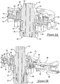
- an apparatus 10 senses the relative position between a first shaft 12 and a second shaft 14. The relative position may then be used to derive the torque applied between the first and second shafts 12, 14.
- the apparatus 10 may be used in an power steering system 16 to provide a measurement of input torque generated by a driver turning a steering wheel (not shown).
- the input torque is used to provide appropriate hydraulic or electrical assist to allow the driver to complete a turn with minimal effort, but increased stability.
- the first shaft 12 is connected to the steering wheel.
- the second shaft 14 is coupled to a steering system (not shown), for example, as a rack and pinion gear mechanism.
- a compliant member such as a torsion bar 18 couples the first and second shafts 12, 14.
- the first and second shafts 12, 14 are moveable relative to each other through a predetermined range, e.g., ⁇ 8 or ⁇ 12 degrees. It should be noted that the range of relative movement will be dependent upon application. The present invention is not limited to any given range of relative movement.
- a position sensor may be used to measure rotation of the first or second shafts 12, 14.
- the position sensor may be a contact or non-contact sensor.
- the apparatus 10 may contained within a housing 22, which may also contain portions of the first and second shafts 12, 14 and components of the power steering system. Such steering systems 16 are well known in the art and are, therefore, not further discussed.
- the apparatus 10 includes a first rotor assembly 24 and a second rotor assembly 26.
- the first rotor assembly 24 is coupled to the first shaft 12 and is centered on an axis 28.
- the second rotor assembly 26 is coupled to the second shaft 14.
- the first and second rotor assemblies 24, 26 are coaxial.
- the first rotor assembly 24 includes a rotor 30 centered on the axis 28.
- the rotor 30 includes a plurality of slots or flats 32.
- the first rotor assembly 24 includes a plurality of magnets 34 located in each slot or flat 32.
- the magnets 34 may be affixed or held in place in any appropriate manner such as by an adhesive or crimping.
- a retaining member 36 may be used along with, or in place of, the adhesive.
- the retaining member 36 is made from a non-magnetic material, such as plastic.
- the retaining member 36 is overmolded the combined rotor 30 and magnets 34, once the magnets 34 are inserted into the slots or flats 32.
- the first rotor assembly 24 is pressed onto the first shaft 12.
- the first shaft 12 may have an enlarged portion 38 which forms a press-fit with the first rotor assembly 24.
- the first rotor 30 is composed of a soft magnetic material, such as a nickel iron alloy.
- the first rotor 30 may be made using a stamping process or may be made from a powdered metal using a sintering process or through a machining process.
- the rotor 30 includes an inner surface 40 and an outer surface 42.
- the slots or flats 32 are formed in the outer surface 42.
- the inner surface 40 has an associated inner radius 44 and the outer surface 42 has an associated outer radius 46.
- the rotor 30 forms support structures 48.
- the inner radius 44 is defined by the inner surface 40 at the center of a support structure 48. In one aspect of the present invention, the inner radius 44 is greater than outer radius 46.
- the magnets 34 are disposed evenly around the circumference of the rotor 30.
- the spacing between, i.e., the width of the support structures 48, the magnets 34 are approximately the width of the magnets 34 or slots or flats 32.
- the support structures 48 serves as the path the magnetic flux flows through to complete the magnetic circuit on its path through the magnets 34.
- top surface of the magnets 34 does not protrude beyond the support structures 48 in the axial direction.
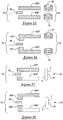
- the rotor assembly 24 includes six square magnets 34, such as shown in Figure 12A .
- the front surface of the magnet 34 in Figure 12A is square. In an alternative embodiment, the front surface of the magnet 34 is rectangular.
- the front surface of the magnet 34 in Figure 12A is the North pole of the magnet 34.
- the back surface of the magnet 34 is the South pole.
- one of the front or back surface of the magnet 34 is adjacent the rotor 30.
- Four side surfaces adjoin the front and back surfaces of the magnets 34. At least one pair of edges formed by one of the front and back surfaces and the four side surfaces of the magnets 34 are rounded.
- all of the magnets 34 on the rotor are orientated in a similar manner, i.e., one of the North pole or the South pole is “down", i.e., adjacent the rotor 30, and the other pole, is "up”.
- the orientations of the magnets 34 are alternated, one magnet 34 is orientated “up” and the adjacent magnets 34 are orientated "down”.
- the first rotor assembly 24 may also include other magnet arrangements.
- the rotor assembly 24 may include two adjacent rows 50, 52 of magnets 34.
- Each row 50, 52 may include a plurality of magnets 34 spaced equidistantly around the circumference of the rotor 30.
- Each magnet 34 in one of the rows 50,52 may be orientated in the same direction or orientated in the opposite direction from the adjacent magnets.
- the rotor assembly 24 may include one or more ring magnets 54, as shown in Figure 12C .
- the ring magnet 54 has one or more pairs of adjacent poles 56, i.e., each pair having a North pole and a South pole. The North pole of one pair being adjacent the South pole of the next pair.
- the ring magnet 54 may have six pairs of North and South poles.
- the ring magnet 54 has an interior bore 58 which may surround the rotor 34.
- the ring magnet 54 may be affixed to the rotor 34 by an adhesive and/or the retaining member 36 and/or any suitable means. If more than one ring magnet 54 is provided, the ring magnets 54 are parallel.
- each magnet slot or flat 32 is defined by a plane 60.
- a centerpoint 62 of the plane 60 is tangent to the outer radius 46.
- Associated with each slot or flat 32 may also include stress relief slots 64. Additionally, a non-continuous inner diameter 47 may also eliminate hoop stress.
- the second rotor assembly 26 includes a first stator plate 66 and a second stator plate 68.
- the first and second stator plates 66, 68 are parallel to each other.
- the first stator plate 66 includes an upper surface 66A and a lower surface 66B.
- the second stator plate 68 also includes an upper surface 68A and a lower surface 68B.
- the upper and lower surfaces 66A, 66B, 68A, 68B are parallel.
- the lower surface 66B of the first stator plate 66 faces the upper surface 68A of the second stator plate 68, as shown.
- the first and second stator plates 66, 68 may be manufactured using a stamping process may be made from a powdered metal using a sintering process, or may be made using a machining process.
- the first stator plate 66 includes a circular base 66C and a plurality of teeth 66D extending from the circular base 66C in a radial direction.
- the second stator plate 68 includes a circular base 68C and a plurality of teeth 68D extending from the circular base 68C in a radial direction.
- the teeth 66D, 68D of the first and second stator plates 66, 68 may be in-phase or offset from each other.
- the first and second plates 66, 68 are planar. As shown in Figures 3A and 5 the upper surface of the teeth 66D, 68D is co-planar with the upper surface 66A, 68A of the respective stator plate 66, 68 and the lower surface of the teeth 66D, 68D is co-planar with the lower surface 66B, 68B of the respective stator plate 66, 68. In other words, the teeth 66D on the first stator plate 66 do not axially intersect with the teeth 68D on the second stator plate 68, i.e., do not intersect with a common plane perpendicular to the axis 28,.
- the first and second stator plates 66, 68 form a gap 70 between the lower surface 66B of the first stator plate 66 and the upper surface 68A of the second stator plate 68. As shown, the gap 70 has a uniform thickness.
- the second rotor assembly 26 includes a retaining member 72.
- the retaining member 72 is made form a non-magnetic material, such as plastic.
- the retaining member 72 is overmolded the first and second stator plates 66, 68.
- the first stator plate 66 and the second stator plate 68 are retained by the retaining member 72 which fixes the relative position thereof.
- the retaining member 72 retains the first and second stator plates 66, 68 in a predetermined relationship, i.e., to maintain the size of the desired gap 70 and the angular relationship between the first and second stator plates 66, 68.
- the retaining member 72 also includes an inner bore 78.
- the retaining member 72 is slipped over the second shaft 14, the inner bore 78 forming a friction fit with the second shaft 14.
- the second shaft 14 may also include a number of splines (not shown) which form a spline interface with the retaining member 72.
- a retaining ring 80 fitted over an outer surface 82 of the retaining member 74 opposite the inner bore 78 may be used also as a redundant feature to retain the retaining member 72 on the second shaft 14.
- the apparatus 10 includes at least one sensing device 84 disposed within the gap 70 for sensing a change in magnetic flux.
- the sensing device 84 e.g., a hall effect sensor
- the sensing device 84 and the circuit board 86 are contained with a probe housing 88.
- the probe housing 88 is either mounted to a stationery member (not shown) or rotationally mounted to a bearing surface (not shown) and serves to accurately position the sensing device 84 within the gap 70.
- a wire harness 90 provides power and delivers signals from the sensing device 84. Alternately or additionally, a wedge gage plate, or screws may be used to assist in accurately positioning the sensing device 84 in the gap 70.
- the teeth 66D, 68D of the first and second stator plates 66, 68 are offset or out-phase.
- the magnetic field measured by the sensing device 84 varies depending on the alignment of the magnets in the first rotor assembly 24 and the teeth 68D, 68D. As shown in Figure 4 , the radial gap between the teeth 66D, 68D and the top of the magnets 34 is greater than the gap between the teeth 66D, 68D and the top of the supporting structures 48.
- the magnetic circuit formed by the magnets has mainly two regions called upper magnetic zone formed between upper stator and the magnets and lower magnetic zone formed between lower stator and the magnets.
- the differential flux between these two zones flows through the measurement slot where magnetosensitive elements sense the field.
- both of the zones produce the same amount of flux, hence the differential flux crossing through the gap 70 is zero.
- the differential flux either flows up or down in the measurement slot.
- FIG. 6 an exemplary graph of flux density measured by the sensing device 84 as a function of angular displacement between the first and second shafts 12, 14 is shown. At zero degrees, no torque is being on the first shaft 12 and no flux is measured.
- the flux density measured by the sensing device 84 increases or decreases depending on the direction of travel of the first shaft 12.
- the maximum relative displacement between the first and second shafts 12, 14 is +/- ⁇ degrees with an associated -/-G Gauss of flux density variation. It should be noted that the graph of Figure 6 is exemplary and for illustrative purposes only.
- two sensing devices 84 may be used. Any changes in magnetic flux at constant displacement between the first and second rotor assemblies 24, 26 over 360 degrees will have the same effect on each device 84.
- the spacing of the sensing devices 84 is dependent upon the number of magnetic poles and teeth of the first and second rotor assemblies 84, respectively.
- This variation will cause an oscillation of the output over 360 degrees which will appear with a frequency equal to the number of magnetic poles and stator teeth located on the first and second rotor assemblies.
- two sensing devices 84 may be used.
- this oscillation will have a 6th order ripple and will be referred to as a "6 per rev".
- This six per rev will appear in the signal from both sensing devices 84 (T1 and T2).
- the T1 and T2 signals have opposite polarities.
- the black rectangle inside the Hall sensors 84 represents the sensitive area of the device.
- the output signals are proportional to the normal component of the flux passing through the sensitive area. It is desirable that the oscillation affects the T1 and T2 signals in the same manner at the same time.
- the Hall sensors should be separated such that the oscillations in T1 and T2 remain in phase (since they are inverted to each other).
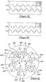
- the ripple effect in the calculated torque signal is minimized. Due to mechanical packaging limitations with regard to the locations of the sensitive areas of the two Hall sensors with respect to each other, a certain phase shift exists between T1 and T2. This phase shift is shown in Figure 3C as ⁇ 1 .
- Figure 3E illustrates the T1 and T2 signals over 360 degrees with no compensation. In this particular embodiment our goal is to minimize the oscillation in the calculated torque signal.
- Figure 3D shows the implementation of this concept in the torque sensor.
- R is denoting the radial location of the Hall sensors from the axis of the shaft.
- Figure 3F illustrates the T1 and T2 signals after appropriately spacing the hall probes to minimize the ripple in the calculated torque signal.
- a non-contacting position sensor 92 may be used with the apparatus 10 for sensing the relative and/or absolute position of the first shaft 12 and the second shaft 14.
- the position sensor 92 which is shown diagrammatically, includes a ring magnet 94 magnetized diametrically resulting in two-pole (N-S) configuration.
- the ring magnet 94 and the ring shield 96 are concentric with the second shaft 12 and rotate therewith.
- the relative sensor section can detect 0 ⁇ 360 degrees in either direction of rotation.
- a disk magnet 98 magnetized through the diameter and a ring shield 10, which are external to the ring shield 96 and fixed relative to the first shaft.
- the disk magnet is used to provide absolute position of the shaft since the shaft can rotate ⁇ 810 degrees.
- the turns counter section of the sensor rotates in steps of 180 degrees revolution of the first shaft or the relative sensor section and connected there by Geneva wheel gear mechanism.
- both sensor section there are two Hall sensors placed at quadrature. They both use sine and cosine signals to extract position information.
- the teeth 66D, 68D may have different shapes. Various examples of teeth 66D, 68D are shown in Figures 8A, 8B, 8C, 8D . However, it should be noted that the present invention is not limited to any one shape of the teeth 66D, 68D.
- the teeth 66D, 68D may be in phase or out of phase. If the teeth 66D, 68D are in-phase or aligned, a centerline 104 of the teeth 66D of the first stator plate 66 is aligned with a centerline 104 of the teeth 68D of the second stator plate 68. If the teeth 66D, 68D are out-of phase, than the centerline 104 of the teeth 66D of the first stator plate 66 are offset from the centerline 104 of the teeth 68D of the second stator plate 68, as shown in Figures 3A and 4 .
- teeth 66D, 68D are out-of-phase, there may be a radial gap between edges of the teeth 66D, 68D as shown best in Figure 4 , the edges of the teeth 66D, 68D may be aligned, or the teeth 66D, 68D may at least partially overlap.
- edges of the teeth 66D, 68D of one of the first and second stator plates 66, 68 are adjacent with an edge of one of the teeth 66D, 68D of the other of the first and second plates 66, 68.
- the shape of the teeth 66D, 68D is shown in Figure 8C and the relationship between the teeth 66D, 68D is shown in Figures 11D and 11E .
- the first and second plates 66, 68 include axial members 66E, 68E which extend in opposite direction from the circular base 66C 68D of the first and second stator plates 66, 68, respectively to form the gap 70.
- the axial members 66E, 68E extend around the circumference of the circular base 66C, 68D of each stator plate 66, 68.
- Figure 9A shows a cross-section view of the teeth 66D, 68D.
- Figure 9B shows a top-down view of the teeth 66D, 68D.
- Figure 9C shows a front view of the teeth 66D, 68D (from the first rotor assembly 24).
- Figure 10A shows a cross-section view of the teeth 66D, 68D.
- Figure 10B shows a top-down view of the teeth 66D, 68D.
- Figure 10C shows a front view of the teeth 66D, 68D (from the first rotor assembly 24).
- the teeth 66D, 68D are out-of-phase and have the shape as shown in 8C.
- the edges of the teeth 66D, 68D are radially adjacent (see above and Figures 11D and 11E).
- Figure 11A shows a cross-section view of the teeth 66D, 68D.
- Figure 11B shows a top-down view of the teeth 66D, 68D.
- Figure 11C shows a front view of the teeth 66D, 68D (from the first rotor assembly 24).
- Figure 13 shows an apparatus 10 with a first rotor assembly 24 which a plurality of unipolar magnet 34 in first and second rows 50, 52 and a second rotor assembly 26 with first and second stator plates 66, 68.
- the first and second stator plates 66, 68 are planar and in phase.
- Figure 14 shows an apparatus 10 with a first rotor assembly 24 which a plurality of unipolar magnet 34 in first and second rows 50, 52 and a second rotor assembly 26 with first and second stator plates 66, 68 with axial members 66E, 68E.
- the first and second stator plates 66, 68 are in phase.
- Figure 15 shows an apparatus 10 with a first rotor assembly 24 with two ring magnets 34 and a second rotor assembly 26 with first and second stator plates 66, 68 which are planar.
- the first and second stator plates 66, 68 are in phase.
- FIG 16 shows an apparatus 10 with a first rotor assembly 24 with two ring magnets 34 and a second rotor assembly 26 with first and second stator plates 66, 68.
- Each stator plate 66, 68 includes an axial member 66E, 68E.
- the first and second stator plates 66, 68 are in phase.
- Figure 17 shows an apparatus 10 with a first rotor assembly 24 with a row of unipolar magnets 34 and a second rotor assembly 26 with first and second stator plates 66, 68.
- the first and second rotor plates 66, 68 are planar.
- Figure 18 shows an apparatus 10 with a first rotor assembly 24 with a row of unipolar magnets 34 and a second rotor assembly 26 with first and second stator plates 66, 68.
- the first and second stator plates 66, 68 include an axial member 66E, 68E. the first and second rotor plates 66, 68 are out of phase.
- Figure 19 shows an apparatus 10 with a first rotor assembly 24 with first and second rows 50, 52 of unipolar magnets 34 and a second rotor assembly 26 with first and second stator plates 66, 68.
- the first and second stator plates 66, 68 are out of phase.
- Figure 20 shows an apparatus 10 with a first rotor assembly 24 with first and second rows 50, 52 of unipolar magnets 34 and a second rotor assembly 26 with first and second stator plates 66, 68.
- the first and second stator plates 66, 68 are out of phase and include an axial member 66E, 68E.
- Figure 21 shows an apparatus 10 with a first rotor assembly 24 with a ring magnet 34 and a second rotor assembly 26 with first and second stator plates 66, 68.
- the first and second stator plates are out of phase and planar.
- Figure 22 shows an apparatus 10 with a first rotor assembly 24 with a ring magnet 34 and a second rotor assembly with first and second stator plates 66, 68.
- the first and second stator plates are out of phase and include an axial member 66E, 68E.
- Figure 23 shows an apparatus 10 with a first rotor assembly 24 with two ring magnets 34 and a second rotor assembly 26 with first and second stator plates 66, 68.
- the first and second stator plates 66, 68 are out of phase and planar.
- Figure 24 shows an apparatus 10 with a first rotor assembly 24 with two ring magnets 34 and a second rotor assembly 26 with first and second stator plates 66, 68.
- the first and second stator plates 66, 68 are out of phase and include an axial member 66E, 68E.
Landscapes
- Physics & Mathematics (AREA)
- General Physics & Mathematics (AREA)
- Electromagnetism (AREA)
- Transmission And Conversion Of Sensor Element Output (AREA)
- Permanent Field Magnets Of Synchronous Machinery (AREA)
- Power Steering Mechanism (AREA)
Claims (36)
- Appareil (10) pour mesurer le déplacement relatif entre un premier arbre (12) et un second arbre (14), comprenant :un premier assemblage à rotor (24) qui est couplé au premier arbre (12) et qui est centré sur un axe (28) ;au moins un aimant (34) ayant un champ magnétique qui est disposé sur le premier assemblage à rotor (24) ;un second assemblage à rotor (26) qui est couplé au second arbre (14), le premier assemblage à rotor (24) et le second assemblage à rotor (26) étant coaxiaux, le second assemblage à rotor (26) ayant une première plaque de stator (66) et une seconde plaque de stator (68), chacune de la première plaque de stator (66) et de la seconde plaque de stator (68) ayant une surface supérieure (66A, 68A) et une surface inférieure (66B, 68B), la surface supérieure (66A, 68A et la surface inférieure (66B, 68B) étant parallèles, la première plaque de stator (66) et la seconde plaque de stator (68) ayant une pluralité de dents (66D, 68D), chaque dent (66D, 68D) ayant une surface supérieure et une surface inférieure, la première plaque de stator (66) et la seconde plaque de stator (68) formant un intervalle (70) entre la surface inférieure (66B) de la première plaque de stator (66) et la surface supérieure (68A) de la seconde plaque de stator (68), l'intervalle (70) ayant une épaisseur uniforme ; etun dispositif détecteur (84) disposé à l'intérieur de l'intervalle (70) pour détecter un flux magnétique du champ magnétique,caractérisé en ce quela pluralité de dents (66D, 68D) de la première plaque de stator (66) et de la seconde plaque de stator (68) s'étendent dans une direction radiale de l'axe (28),la surface supérieure de chaque dent (66D, 68D) est dans un plan avec la surface supérieure (66A, 68A) de la plaque de stator respective (66, 68), et la surface inférieure de chaque dent (66D, 68D) est dans un plan avec la surface inférieure (66B, 68B) de la plaque respective (66, 68).
- Appareil (10) selon la revendication 1, comprenant en outre un élément souple (18) couplé entre le premier arbre (12) et le second arbre (14) pour permettre un mouvement relatif entre ceux-ci.
- Appareil (10) selon la revendication 1, comprenant en outre un élément de retenue (36) pour maintenir la première plaque de stator (66) et la seconde plaque de stator (68) et pour fixer leur position relative, respectivement, et qui est couplé de manière fixe à l'arbre inférieur.
- Appareil (10) selon la revendication 3, dans lequel chaque plaque de stator (66, 68) inclut une section de base circulaire (66C, 68C), la pluralité de dents (66D, 68D) s'étendant depuis la section de base circulaire (66C, 68C).
- Appareil (10) selon la revendication 1, dans lequel le dispositif de mesure (84) est monté sur un élément stationnaire (86) ou sur une surface porteuse.
- Appareil (10) selon la revendication 3, dans lequel l'élément de retenue (36) inclut un perçage destiné à être engagé à la presse sur le second arbre (14).
- Appareil (10) selon la revendication 3, dans lequel l'élément de retenue (36) est réalisé à partir d'un matériau non magnétique.
- Appareil (10) selon la revendication 3, dans lequel l'élément de retenue (36) est réalisé en matière plastique.
- Appareil (10) selon la revendication 3, dans lequel la première plaque de stator (66) et la seconde plaque de stator (68) sont collées et/ou serties sur l'élément de retenue (36).
- Appareil (10) selon la revendication 3, dans lequel l'élément de retenue (36) est surmoulé sur la première plaque de stator (66) et sur la seconde plaque de stator (68).
- Appareil (10) selon la revendication 1, dans lequel la première plaque de stator (66) et la seconde plaque de stator (68) sont réalisées en utilisant un processus d'estampage ou un processus de moulage de métal par injection, ou un processus de coulée.
- Appareil (10) selon la revendication 1, dans lequel la première plaque de stator (66) et la seconde plaque de stator (68) sont réalisées à partir d'un métal en poudre en utilisant un processus de frittage ou un processus de "bonding".
- Appareil (10) selon la revendication 1, dans lequel le premier assemblage à rotor (24) a une circonférence et une pluralité de fentes ou de méplats (32) espacé(e)s de façon égale autour de la circonférence, l'appareil (10) incluant une pluralité d'aimants (34), chaque aimant (34) étant placé dans l'une des fentes ou dans l'un des méplats (32).
- Appareil (10) selon la revendication 13, dans lequel la pluralité d'aimants (34) sont monopolaires.
- Appareil (10) selon la revendication 13, dans lequel chaque aimant (34) a une première et une seconde surface parallèles et quatre surfaces latérales, la première et la seconde surface parallèles étant parallèles à l'axe (28), au moins une paire de bords opposés formés par l'une des surfaces latérales et par la première surface parallèle étant arrondis.
- Appareil (10) selon la revendication 13, dans lequel chaque aimant (34) a une première et une seconde surface parallèles et quatre surfaces latérales, la première et la seconde surface parallèles étant parallèles à l'axe (28), la première et la seconde surface parallèles étant rectangulaires.
- Appareil (10) selon la revendication 13, dans lequel chaque aimant (34) a une première et une seconde surface parallèles et quatre surfaces latérales, la première et la seconde surface parallèle étant parallèles à l'axe (28), la première et la seconde surface parallèles étant carrées.
- Appareil (10) selon la revendication 13, dans lequel la pluralité d'aimants (34) sont dans une unique rangée autour de la circonférence du premier assemblage à rotor (24).
- Appareil (10) selon la revendication 13, dans lequel la pluralité d'aimants (34) sont dans deux rangées (50, 52) autour de la circonférence du premier assemblage à rotor (24).
- Appareil (10) selon la revendication 1, dans lequel le premier assemblage à rotor (24) présente une circonférence, ledit au moins un aimant (34) étant un aimant annulaire (54).
- Appareil (10) selon la revendication 20, comprenant en outre un second aimant annulaire (54), le premier aimant annulaire (34) et le second aimant annulaire (54) étant dans des plans parallèles perpendiculaires à l'axe (28).
- Appareil (10) selon la revendication 1, comprenant en outre un second dispositif détecteur (T2) présentant un déplacement par rapport à l'autre dispositif détecteur (T1), de sorte que des changements quelconques du flux magnétique à déplacement constant entre le premier assemblage à rotor (24) et le second assemblage à rotor (26) sur 360° auront le même effet sur chaque dispositif (T1, T2).
- Appareil (10) selon la revendication 1, dans lequel les dents (66D, 68D) de la première plaque de stator (66) et de la seconde plaque de stator (68) sont en phase.
- Appareil (10) selon la revendication 1, dans lequel les dents (66D, 68D) de la première plaque (66) et de la seconde plaque (68) sont déphasées.
- Appareil (10) selon la revendication 24, dans lequel un bord de l'une des dents (66D, 68D) d'une plaque parmi la première plaque (66) et la seconde plaque (68) est adjacent à un bord de l'une des dents (66D, 68D) de l'autre plaque parmi la première plaque (66) et la seconde plaque (68).
- Appareil (10) selon la revendication 25, dans lequel au moins une portion du bord de l'une des dents (66D, 68D) d'une plaque parmi la première plaque (66) et la seconde plaque (68) et au moins une portion du bord de l'une des dents (66D, 68D) de l'autre plaque parmi la première plaque (66) et la seconde plaque (68) se chevauchent.
- Appareil (10) selon la revendication 25, dans lequel au moins une portion du bord de l'une des dents (66D, 68D) d'une plaque parmi la première plaque (66) et la seconde plaque (68) et au moins une portion du bord de l'une des dents (66D, 68D) de l'autre plaque parmi la première plaque (66) et la seconde plaque (68) forment un intervalle.
- Appareil (10) selon la revendication 1, incluant un assemblage à rotor destiné à être utilisé dans un détecteur pour mesurer un déplacement relatif entre un premier arbre (12) et un second arbre (14), comprenant additionnellement un élément de retenue (36) pour maintenir la première plaque de stator (66) et la seconde plaque de stator (68), respectivement.
- Appareil (10) selon la revendication 28, dans lequel chaque plaque de stator (66, 68) inclut une section de base circulaire (66C, 68C), la pluralité de dents (66D, 68D) s'étendant depuis la section de base circulaire (66C, 68C).
- Appareil (10) selon la revendication 28, dans lequel l'élément de retenue (36) enserre sensiblement la première plaque de stator (66) et la seconde plaque de rotor (68) pour fixer leur position relative.
- Appareil (10) selon la revendication 28, dans lequel l'élément de retenue (36) est réalisé en un matériau non magnétique.
- Appareil (10) selon la revendication 28, dans lequel les dents (66D, 68D) de la première plaque de stator (66) et de la seconde plaque de stator (68) sont en phase.
- Appareil (10) selon la revendication 28, dans lequel les dents (66D, 68D) de la première plaque (66) et de la seconde plaque (68) sont déphasées.
- Appareil (10) selon la revendication 28, dans lequel les dents (66D, 68D) s'étendent dans une direction radiale par rapport à un axe (28), chaque dent (66D, 68D) ayant une surface supérieure et une surface inférieure, la surface supérieure de chaque dent (66D, 68D) étant dans un plan avec la surface supérieure (66A, 68A) de la plaque de stator respective (66, 68), la surface inférieure de chaque dent étant dans un plan avec la surface inférieure (66D, 68B) de la plaque respective (66, 68).
- Appareil (10) selon la revendication 28, dans lequel l'élément de retenue (36) est surmoulé sur la première plaque de stator (66) et sur la seconde plaque de stator (68).
- Appareil (10) selon la revendication 28, dans lequel la première plaque de stator (66) et la seconde plaque de stator (68) sont collées et/ou serties sur l'élément de retenue (36).
Applications Claiming Priority (3)
| Application Number | Priority Date | Filing Date | Title |
|---|---|---|---|
| US54251104P | 2004-02-06 | 2004-02-06 | |
| US10/795,908 US7021160B2 (en) | 2003-06-10 | 2004-03-08 | Apparatus for sensing position and/or torque |
| PCT/US2004/022539 WO2005083380A1 (fr) | 2004-02-06 | 2004-07-13 | Appareil conçu pour detecter une position et/ou un couple |
Publications (3)
| Publication Number | Publication Date |
|---|---|
| EP1714123A1 EP1714123A1 (fr) | 2006-10-25 |
| EP1714123A4 EP1714123A4 (fr) | 2007-09-12 |
| EP1714123B1 true EP1714123B1 (fr) | 2018-11-14 |
Family
ID=34915549
Family Applications (1)
| Application Number | Title | Priority Date | Filing Date |
|---|---|---|---|
| EP04778176.0A Expired - Lifetime EP1714123B1 (fr) | 2004-02-06 | 2004-07-13 | Appareil concu pour detecter une position et/ou un couple |
Country Status (4)
| Country | Link |
|---|---|
| US (2) | US7021160B2 (fr) |
| EP (1) | EP1714123B1 (fr) |
| JP (1) | JP2007520720A (fr) |
| WO (1) | WO2005083380A1 (fr) |
Families Citing this family (41)
| Publication number | Priority date | Publication date | Assignee | Title |
|---|---|---|---|---|
| US7210360B2 (en) * | 2003-06-16 | 2007-05-01 | Delphi Technologies, Inc. | Apparatus for sensing position and/or torque |
| EP1706716B1 (fr) * | 2004-01-20 | 2011-09-14 | Valeo Schalter und Sensoren GmbH | Dispositif pour determiner un angle de braquage et un couple de rotation exerce sur un arbre de direction |
| US7174795B2 (en) * | 2004-02-06 | 2007-02-13 | Delphi Technologies, Inc. | Integrated non-contacting torque and absolute position sensor for steering applications |
| EP1621447B1 (fr) * | 2004-07-29 | 2013-09-25 | Jtekt Corporation | Détecteur de couple et dispositif de direction assistée électrique |
| JP4812303B2 (ja) * | 2005-01-20 | 2011-11-09 | 株式会社ジェイテクト | トルク検出装置 |
| JP5011794B2 (ja) * | 2005-09-30 | 2012-08-29 | 日本精工株式会社 | 電動パワーステアリング装置 |
| DE102006056418B4 (de) * | 2005-11-30 | 2015-02-19 | Lg Electronics Inc. | Waschmaschine |
| US8953034B1 (en) * | 2006-05-23 | 2015-02-10 | Milan Milosevic | Video imaging device with an integrated battery |
| DE102007059361A1 (de) * | 2006-12-07 | 2008-09-18 | Continental Teves Ag & Co. Ohg | Drehmomentsensoranordnung |
| DE102007057050A1 (de) * | 2007-01-29 | 2008-07-31 | Continental Teves Ag & Co. Ohg | Drehmomentsensor mit verminderter Störanfälligkeit |
| US8083431B2 (en) * | 2007-04-16 | 2011-12-27 | Nexteer (Beijing) Technology Co., Ltd. | Magnetic ring systems for attachment to a shaft and methods of making and using |
| US7639004B2 (en) * | 2007-07-23 | 2009-12-29 | Gm Global Technology Operations, Inc. | Apparatus for sensing angular displacement between first and second rotating shafts including flux collectors |
| JP5440754B2 (ja) * | 2008-04-10 | 2014-03-12 | 日本精工株式会社 | トルク検出器及び電動パワーステアリング装置並びにトルク検出器の製造方法 |
| KR200470045Y1 (ko) * | 2008-12-16 | 2013-11-25 | 엘지이노텍 주식회사 | 일렉트릭 파워 스티어링 시스템 |
| JP5513838B2 (ja) * | 2009-10-21 | 2014-06-04 | カヤバ工業株式会社 | パワーステアリング装置 |
| KR101650455B1 (ko) * | 2009-11-20 | 2016-08-23 | 엘지이노텍 주식회사 | 차량의 조향토크 및 조향각 검출장치 |
| KR101633127B1 (ko) * | 2010-03-30 | 2016-06-24 | 엘지이노텍 주식회사 | 토크 측정장치 |
| CN102893071B (zh) * | 2010-05-02 | 2015-10-07 | Mbs工程有限公司 | 具有改进的旋转稳定性和轴向稳定性的磁体与磁体保持件的组件 |
| US8448528B2 (en) | 2010-09-27 | 2013-05-28 | Bourns Incorporated | Three-piece torque sensor assembly |
| US8390276B2 (en) | 2010-09-27 | 2013-03-05 | Bourns Incorporated | Target magnet assembly for a sensor used with a steering gear |
| DE102012005130B4 (de) * | 2012-03-14 | 2024-11-28 | Volkswagen Aktiengesellschaft | Gehäuse mit einem Kabeldurchführungselement |
| US9479014B2 (en) * | 2012-03-28 | 2016-10-25 | Acme Product Development, Ltd. | System and method for a programmable electric converter |
| DE102012024383A1 (de) * | 2012-12-13 | 2014-06-18 | Valeo Schalter Und Sensoren Gmbh | Vorrichtung mit einer Drehmomentsensoreinrichtung und einer Lenkwinkelsensoreinrichtung für ein Kraftfahrzeug, Kraftfahrzeug und Verfahren zum Herstellen einer Vorrichtung |
| KR102052563B1 (ko) * | 2012-12-17 | 2019-12-05 | 엘지이노텍 주식회사 | 토크센서 |
| US8960020B2 (en) * | 2013-03-15 | 2015-02-24 | Steering Solutions Ip Holding Corporation | Non-contacting torque sensor with injection molded magnets |
| WO2014210524A1 (fr) * | 2013-06-28 | 2014-12-31 | Lord Corporation | Couplemètre à précision améliorée et son procédé d'utilisation |
| KR102055800B1 (ko) * | 2013-09-27 | 2019-12-13 | 엘지이노텍 주식회사 | 토크센서 |
| US10288506B2 (en) * | 2016-10-19 | 2019-05-14 | Steering Solutions Ip Holding Corporation | Integrated torque sensor in controller board and EPS system incorporating the same |
| DE102016124429B4 (de) | 2016-12-15 | 2022-11-03 | Valeo Schalter Und Sensoren Gmbh | Kabeleinrichtung mit Pressfitverbindung, Drehmomentsensoreinrichtung und Drehmomentsensorsystem sowie Kraftfahrzeug |
| JP6666862B2 (ja) * | 2017-01-23 | 2020-03-18 | 株式会社Soken | トルク検出装置 |
| WO2020040563A1 (fr) * | 2018-08-23 | 2020-02-27 | 엘지이노텍 주식회사 | Dispositif de détection |
| KR102651815B1 (ko) * | 2018-08-23 | 2024-03-29 | 엘지이노텍 주식회사 | 센싱 장치 |
| KR102636852B1 (ko) * | 2018-08-23 | 2024-02-19 | 엘지이노텍 주식회사 | 센싱 장치 |
| KR102599287B1 (ko) * | 2018-08-23 | 2023-11-07 | 엘지이노텍 주식회사 | 센싱 장치 |
| KR102106294B1 (ko) * | 2018-09-21 | 2020-05-04 | 주식회사 만도 | 자동차 조향장치 |
| KR102660627B1 (ko) * | 2019-03-12 | 2024-04-25 | 엘지이노텍 주식회사 | 센싱 장치 |
| KR102698898B1 (ko) * | 2019-05-22 | 2024-08-27 | 엘지이노텍 주식회사 | 센싱 장치 |
| CN112109798A (zh) | 2019-06-20 | 2020-12-22 | 操纵技术Ip控股公司 | 用于转向扭矩传感器的杂散磁场抵消 |
| CN110220686B (zh) * | 2019-06-26 | 2024-06-28 | 上海电气集团上海电机厂有限公司 | 保持柴油同步发电机转子磁极螺杆拉紧力试验装置及方法 |
| US11692903B2 (en) | 2020-10-01 | 2023-07-04 | Saudi Arabian Oil Company | Valve diagnostic and performance system |
| US11441697B2 (en) | 2020-10-01 | 2022-09-13 | Saudi Arabian Oil Company | Valve diagnostic and performance system |
Family Cites Families (52)
| Publication number | Priority date | Publication date | Assignee | Title |
|---|---|---|---|---|
| GB588677A (en) | 1945-02-12 | 1947-05-30 | Siemens Brothers & Co Ltd | Electrical arrangements for measuring small movements |
| US3671841A (en) * | 1970-05-01 | 1972-06-20 | Tri Tech | Stepper motor with stator biasing magnets |
| US4784002A (en) | 1986-12-17 | 1988-11-15 | Atsugi Motor Parts Company, Limited | Torque sensor |
| JPS63265127A (ja) * | 1987-04-23 | 1988-11-01 | Hitachi Ltd | トルクセンサ |
| JP2613449B2 (ja) * | 1988-09-30 | 1997-05-28 | 株式会社コパル | 相対変位検出装置 |
| US4984474A (en) | 1988-09-30 | 1991-01-15 | Copal Company Limited | Torque sensor |
| US4939456A (en) | 1988-12-23 | 1990-07-03 | General Motors Corporation | Position sensor including a thin film indium arsenide magnetoresistor on a permanent magnet |
| US5188038A (en) * | 1991-02-11 | 1993-02-23 | Shanley Thomas E | Railroad car derailment safety device |
| US5591925A (en) | 1991-07-29 | 1997-01-07 | Garshelis; Ivan J. | Circularly magnetized non-contact power sensor and method for measuring torque and power using same |
| US5351555A (en) | 1991-07-29 | 1994-10-04 | Magnetoelastic Devices, Inc. | Circularly magnetized non-contact torque sensor and method for measuring torque using same |
| US5520059A (en) | 1991-07-29 | 1996-05-28 | Magnetoelastic Devices, Inc. | Circularly magnetized non-contact torque sensor and method for measuring torque using same |
| FR2691534B1 (fr) | 1992-05-19 | 1994-08-26 | Moving Magnet Tech | Capteur de position à aimant permanent et sonde de hall. |
| JP2576070Y2 (ja) * | 1992-06-29 | 1998-07-09 | 株式会社ユニシアジェックス | トルクセンサ |
| DE4333199C2 (de) | 1993-09-29 | 1995-08-31 | Daimler Benz Ag | Sensor zur berührungslosen Drehmomentmessung an einer Welle sowie Meßschicht für einen solchen Sensor |
| US5434504A (en) | 1993-10-01 | 1995-07-18 | International Business Machines Corporation | Position sensors for linear motors including plural symmetrical fluxes generated by a planar drive coil and received by planar sense coils being colinear along an axis of motion |
| FR2712982B1 (fr) | 1993-11-26 | 1996-02-09 | Labinal | Dispositif de mesure différentielle de couple. |
| US5491407A (en) * | 1995-02-03 | 1996-02-13 | Kearney-National, Inc. | Wheel bearing speed sensor |
| US5725023A (en) | 1995-02-21 | 1998-03-10 | Lectron Products, Inc. | Power steering system and control valve |
| JP2905119B2 (ja) * | 1995-06-30 | 1999-06-14 | 株式会社東芝 | 洗濯機 |
| US5627465A (en) | 1995-10-25 | 1997-05-06 | Honeywell Inc. | Rotational position sensor with mechanical adjustment of offset and gain signals |
| DE59605586D1 (de) | 1995-11-17 | 2000-08-17 | Kostal Leopold Gmbh & Co Kg | Winkelsensor |
| US6275025B1 (en) * | 1996-08-23 | 2001-08-14 | Mannesmann Vdo Ag | Magnetic position sensor |
| JP3370901B2 (ja) * | 1996-09-13 | 2003-01-27 | 株式会社日立製作所 | 永久磁石回転電機およびそれを用いた電動車両 |
| US5889215A (en) | 1996-12-04 | 1999-03-30 | Philips Electronics North America Corporation | Magnetoelastic torque sensor with shielding flux guide |
| US5907105A (en) | 1997-07-21 | 1999-05-25 | General Motors Corporation | Magnetostrictive torque sensor utilizing RFe2 -based composite materials |
| US6047805A (en) * | 1997-09-29 | 2000-04-11 | Inertia Dynamics, Inc. | Electric clutch and brake |
| US6047605A (en) | 1997-10-21 | 2000-04-11 | Magna-Lastic Devices, Inc. | Collarless circularly magnetized torque transducer having two phase shaft and method for measuring torque using same |
| DE19816831A1 (de) | 1998-04-16 | 1999-10-21 | Bosch Gmbh Robert | Vorrichtung zur Drehmomenterfassung |
| DE19817886A1 (de) | 1998-04-22 | 1999-10-28 | Bosch Gmbh Robert | Vorrichtung zur Erfassung des auf eine Welle wirkenden Drehmoments |
| DE59914570D1 (de) * | 1998-08-24 | 2008-01-17 | Levitronix Llc | Sensoranordnung in einem elektromagnetischen Drehantrieb |
| US6169644B1 (en) * | 1998-09-10 | 2001-01-02 | Mitsushita Denki Kabushiki Kaisha | Read/write device |
| US6222287B1 (en) * | 1998-11-06 | 2001-04-24 | Canon Kabushiki Kaisha | Motor |
| US6098741A (en) | 1999-01-28 | 2000-08-08 | Eaton Corporation | Controlled torque steering system and method |
| KR100308385B1 (ko) | 1999-02-10 | 2001-09-26 | 밍 루 | 차량용 동력 조향장치의 반력장치 |
| AU782017B2 (en) * | 1999-10-18 | 2005-06-30 | Lg Electronics Inc. | A driving unit for a drum type washing machine |
| DE19961884C2 (de) | 1999-12-20 | 2003-08-21 | Thomas Strothmann | Anordnung zur kontaktlosen Erfassung von Drehwinkeln, Drehmomenten und sonstigen, vorzugsweise rotatorischen Grössen zwischen rotierenden Teilen |
| US6374664B1 (en) | 2000-01-21 | 2002-04-23 | Delphi Technologies, Inc. | Rotary position transducer and method |
| JP2001227904A (ja) * | 2000-02-14 | 2001-08-24 | Sumitomo Metal Mining Co Ltd | 磁気スケールユニット及びその応用装置 |
| US6424896B1 (en) | 2000-03-30 | 2002-07-23 | Delphi Technologies, Inc. | Steering column differential angle position sensor |
| US6552453B2 (en) * | 2000-05-23 | 2003-04-22 | Japan Servo Co., Ltd. | Magnetic pole position detector for an electric motor |
| DE10036288A1 (de) * | 2000-07-26 | 2002-02-07 | Bosch Gmbh Robert | Unipolar-Transversalflußmaschine |
| TW538578B (en) * | 2000-09-13 | 2003-06-21 | Sanyo Electric Co | Synchronous motor with built-in type permanent magnet |
| JP3879414B2 (ja) * | 2001-02-28 | 2007-02-14 | 株式会社日立製作所 | 空気調和機 |
| FR2821668B1 (fr) | 2001-03-02 | 2003-05-02 | Moving Magnet Tech | Capteur de position, notamment destine a la detection de la torsion d'une colonne de direction |
| FR2824910B1 (fr) * | 2001-05-18 | 2005-05-13 | Denso Corp | Capteur de couple et systeme de direction assistee electrique employant ce capteur |
| US6488115B1 (en) | 2001-08-01 | 2002-12-03 | Delphi Technologies, Inc. | Apparatus and method for steering a vehicle |
| US6701792B2 (en) * | 2001-08-27 | 2004-03-09 | Visteon Global Technologies, Inc. | Torque sensing apparatus for measuring relative torque between two shafts |
| GB2379277B (en) * | 2001-08-27 | 2003-10-15 | Visteon Global Tech Inc | Torque sensing apparatus |
| US6927524B2 (en) * | 2001-11-27 | 2005-08-09 | Wavecrest Laboratories, Llc | Rotary electric motor having separate control modules for respective stator electromagnets |
| US6546780B1 (en) | 2001-12-10 | 2003-04-15 | Delphi Technologies, Inc. | Position sensor method and apparatus |
| US6603230B1 (en) * | 2002-01-30 | 2003-08-05 | Honeywell International, Inc. | Active magnetic bearing assembly using permanent magnet biased homopolar and reluctance centering effects |
| JP2004020527A (ja) * | 2002-06-20 | 2004-01-22 | Nippon Soken Inc | トルクセンサ |
-
2004
- 2004-03-08 US US10/795,908 patent/US7021160B2/en not_active Expired - Lifetime
- 2004-07-13 EP EP04778176.0A patent/EP1714123B1/fr not_active Expired - Lifetime
- 2004-07-13 WO PCT/US2004/022539 patent/WO2005083380A1/fr not_active Ceased
- 2004-07-13 JP JP2006552091A patent/JP2007520720A/ja not_active Ceased
-
2005
- 2005-04-08 US US11/102,096 patent/US7188533B2/en not_active Expired - Lifetime
Non-Patent Citations (1)
| Title |
|---|
| None * |
Also Published As
| Publication number | Publication date |
|---|---|
| US7021160B2 (en) | 2006-04-04 |
| US20040250631A1 (en) | 2004-12-16 |
| WO2005083380A1 (fr) | 2005-09-09 |
| US7188533B2 (en) | 2007-03-13 |
| EP1714123A4 (fr) | 2007-09-12 |
| EP1714123A1 (fr) | 2006-10-25 |
| US20050172727A1 (en) | 2005-08-11 |
| JP2007520720A (ja) | 2007-07-26 |
Similar Documents
| Publication | Publication Date | Title |
|---|---|---|
| EP1714123B1 (fr) | Appareil concu pour detecter une position et/ou un couple | |
| EP2020590B1 (fr) | Appareil destiné à détecter une position et/ou un couple | |
| CN101213431B (zh) | 用于检测角度差的传感器装置 | |
| EP2860504B1 (fr) | Capteur d'indice de couple | |
| EP2511683B1 (fr) | Capteur de couple | |
| US20110000319A1 (en) | Torque sensor | |
| CN103842786B (zh) | 传感器装置 | |
| EP2103910B1 (fr) | Détecteur d'angle de rotation | |
| US12203822B2 (en) | Heterogeneous magnetic and inductive sensors | |
| EP2088398B1 (fr) | Détecteur d'angle de rotation | |
| WO2008075620A1 (fr) | Dispositif de détection d'angle de rotation | |
| KR100915264B1 (ko) | 토크센서 및 이를 구비한 전동식 파워 스티어링 장치 | |
| CN109256905A (zh) | 用于转子位置估计的环形磁体 | |
| US20240255310A1 (en) | Sensing apparatus | |
| US7210360B2 (en) | Apparatus for sensing position and/or torque | |
| US20050160834A1 (en) | Assembly for measuring movement of and a torque applied to a shaft | |
| JP4198362B2 (ja) | 回転角度センサ | |
| US12617464B2 (en) | Sensing device | |
| KR102960223B1 (ko) | 센싱 장치 | |
| CN222441485U (zh) | 一种感应式传感器及电机系统 | |
| EP4202400A1 (fr) | Dispositif de détection | |
| KR20260040400A (ko) | 센싱 장치 | |
| JPH08327473A (ja) | トルクセンサ | |
| JP2007278964A (ja) | 回転角度およびトルク検出装置 |
Legal Events
| Date | Code | Title | Description |
|---|---|---|---|
| PUAI | Public reference made under article 153(3) epc to a published international application that has entered the european phase |
Free format text: ORIGINAL CODE: 0009012 |
|
| 17P | Request for examination filed |
Effective date: 20060906 |
|
| AK | Designated contracting states |
Kind code of ref document: A1 Designated state(s): AT BE BG CH CY CZ DE DK EE ES FI FR GB GR HU IE IT LI LU MC NL PL PT RO SE SI SK TR |
|
| RIN1 | Information on inventor provided before grant (corrected) |
Inventor name: PATTOK, ERIC, D. Inventor name: FENG, SAINAN Inventor name: ISLAM, MOHAMMAD, S. Inventor name: PAVLAWK, RYAN, J. Inventor name: MIELKE, MATTHEW, W. Inventor name: ROSS, CHRISTIAN, E. Inventor name: SEBASTIAN, TOMY |
|
| DAX | Request for extension of the european patent (deleted) | ||
| A4 | Supplementary search report drawn up and despatched |
Effective date: 20070816 |
|
| RAP1 | Party data changed (applicant data changed or rights of an application transferred) |
Owner name: GM GLOBAL TECHNOLOGY OPERATIONS, INC. |
|
| RAP1 | Party data changed (applicant data changed or rights of an application transferred) |
Owner name: GM GLOBAL TECHNOLOGY OPERATIONS LLC |
|
| RAP1 | Party data changed (applicant data changed or rights of an application transferred) |
Owner name: STEERING SOLUTIONS IP HOLDING CORPORATION Owner name: GM GLOBAL TECHNOLOGY OPERATIONS LLC Effective date: 20121122 |
|
| 17Q | First examination report despatched |
Effective date: 20160315 |
|
| GRAP | Despatch of communication of intention to grant a patent |
Free format text: ORIGINAL CODE: EPIDOSNIGR1 |
|
| STAA | Information on the status of an ep patent application or granted ep patent |
Free format text: STATUS: GRANT OF PATENT IS INTENDED |
|
| INTG | Intention to grant announced |
Effective date: 20180523 |
|
| GRAS | Grant fee paid |
Free format text: ORIGINAL CODE: EPIDOSNIGR3 |
|
| GRAA | (expected) grant |
Free format text: ORIGINAL CODE: 0009210 |
|
| STAA | Information on the status of an ep patent application or granted ep patent |
Free format text: STATUS: THE PATENT HAS BEEN GRANTED |
|
| AK | Designated contracting states |
Kind code of ref document: B1 Designated state(s): AT BE BG CH CY CZ DE DK EE ES FI FR GB GR HU IE IT LI LU MC NL PL PT RO SE SI SK TR |
|
| REG | Reference to a national code |
Ref country code: GB Ref legal event code: FG4D |
|
| REG | Reference to a national code |
Ref country code: CH Ref legal event code: EP Ref country code: AT Ref legal event code: REF Ref document number: 1065396 Country of ref document: AT Kind code of ref document: T Effective date: 20181115 |
|
| REG | Reference to a national code |
Ref country code: DE Ref legal event code: R096 Ref document number: 602004053427 Country of ref document: DE |
|
| REG | Reference to a national code |
Ref country code: IE Ref legal event code: FG4D |
|
| REG | Reference to a national code |
Ref country code: NL Ref legal event code: MP Effective date: 20181114 |
|
| REG | Reference to a national code |
Ref country code: AT Ref legal event code: MK05 Ref document number: 1065396 Country of ref document: AT Kind code of ref document: T Effective date: 20181114 |
|
| PG25 | Lapsed in a contracting state [announced via postgrant information from national office to epo] |
Ref country code: FI Free format text: LAPSE BECAUSE OF FAILURE TO SUBMIT A TRANSLATION OF THE DESCRIPTION OR TO PAY THE FEE WITHIN THE PRESCRIBED TIME-LIMIT Effective date: 20181114 Ref country code: BG Free format text: LAPSE BECAUSE OF FAILURE TO SUBMIT A TRANSLATION OF THE DESCRIPTION OR TO PAY THE FEE WITHIN THE PRESCRIBED TIME-LIMIT Effective date: 20190214 Ref country code: ES Free format text: LAPSE BECAUSE OF FAILURE TO SUBMIT A TRANSLATION OF THE DESCRIPTION OR TO PAY THE FEE WITHIN THE PRESCRIBED TIME-LIMIT Effective date: 20181114 Ref country code: AT Free format text: LAPSE BECAUSE OF FAILURE TO SUBMIT A TRANSLATION OF THE DESCRIPTION OR TO PAY THE FEE WITHIN THE PRESCRIBED TIME-LIMIT Effective date: 20181114 |
|
| PG25 | Lapsed in a contracting state [announced via postgrant information from national office to epo] |
Ref country code: PT Free format text: LAPSE BECAUSE OF FAILURE TO SUBMIT A TRANSLATION OF THE DESCRIPTION OR TO PAY THE FEE WITHIN THE PRESCRIBED TIME-LIMIT Effective date: 20190314 Ref country code: GR Free format text: LAPSE BECAUSE OF FAILURE TO SUBMIT A TRANSLATION OF THE DESCRIPTION OR TO PAY THE FEE WITHIN THE PRESCRIBED TIME-LIMIT Effective date: 20190215 Ref country code: NL Free format text: LAPSE BECAUSE OF FAILURE TO SUBMIT A TRANSLATION OF THE DESCRIPTION OR TO PAY THE FEE WITHIN THE PRESCRIBED TIME-LIMIT Effective date: 20181114 Ref country code: SE Free format text: LAPSE BECAUSE OF FAILURE TO SUBMIT A TRANSLATION OF THE DESCRIPTION OR TO PAY THE FEE WITHIN THE PRESCRIBED TIME-LIMIT Effective date: 20181114 |
|
| PG25 | Lapsed in a contracting state [announced via postgrant information from national office to epo] |
Ref country code: IT Free format text: LAPSE BECAUSE OF FAILURE TO SUBMIT A TRANSLATION OF THE DESCRIPTION OR TO PAY THE FEE WITHIN THE PRESCRIBED TIME-LIMIT Effective date: 20181114 Ref country code: CZ Free format text: LAPSE BECAUSE OF FAILURE TO SUBMIT A TRANSLATION OF THE DESCRIPTION OR TO PAY THE FEE WITHIN THE PRESCRIBED TIME-LIMIT Effective date: 20181114 Ref country code: DK Free format text: LAPSE BECAUSE OF FAILURE TO SUBMIT A TRANSLATION OF THE DESCRIPTION OR TO PAY THE FEE WITHIN THE PRESCRIBED TIME-LIMIT Effective date: 20181114 Ref country code: PL Free format text: LAPSE BECAUSE OF FAILURE TO SUBMIT A TRANSLATION OF THE DESCRIPTION OR TO PAY THE FEE WITHIN THE PRESCRIBED TIME-LIMIT Effective date: 20181114 |
|
| REG | Reference to a national code |
Ref country code: DE Ref legal event code: R097 Ref document number: 602004053427 Country of ref document: DE |
|
| PG25 | Lapsed in a contracting state [announced via postgrant information from national office to epo] |
Ref country code: EE Free format text: LAPSE BECAUSE OF FAILURE TO SUBMIT A TRANSLATION OF THE DESCRIPTION OR TO PAY THE FEE WITHIN THE PRESCRIBED TIME-LIMIT Effective date: 20181114 Ref country code: SK Free format text: LAPSE BECAUSE OF FAILURE TO SUBMIT A TRANSLATION OF THE DESCRIPTION OR TO PAY THE FEE WITHIN THE PRESCRIBED TIME-LIMIT Effective date: 20181114 Ref country code: RO Free format text: LAPSE BECAUSE OF FAILURE TO SUBMIT A TRANSLATION OF THE DESCRIPTION OR TO PAY THE FEE WITHIN THE PRESCRIBED TIME-LIMIT Effective date: 20181114 |
|
| PLBE | No opposition filed within time limit |
Free format text: ORIGINAL CODE: 0009261 |
|
| STAA | Information on the status of an ep patent application or granted ep patent |
Free format text: STATUS: NO OPPOSITION FILED WITHIN TIME LIMIT |
|
| 26N | No opposition filed |
Effective date: 20190815 |
|
| PG25 | Lapsed in a contracting state [announced via postgrant information from national office to epo] |
Ref country code: SI Free format text: LAPSE BECAUSE OF FAILURE TO SUBMIT A TRANSLATION OF THE DESCRIPTION OR TO PAY THE FEE WITHIN THE PRESCRIBED TIME-LIMIT Effective date: 20181114 |
|
| PG25 | Lapsed in a contracting state [announced via postgrant information from national office to epo] |
Ref country code: MC Free format text: LAPSE BECAUSE OF FAILURE TO SUBMIT A TRANSLATION OF THE DESCRIPTION OR TO PAY THE FEE WITHIN THE PRESCRIBED TIME-LIMIT Effective date: 20181114 |
|
| REG | Reference to a national code |
Ref country code: CH Ref legal event code: PL |
|
| GBPC | Gb: european patent ceased through non-payment of renewal fee |
Effective date: 20190713 |
|
| PG25 | Lapsed in a contracting state [announced via postgrant information from national office to epo] |
Ref country code: TR Free format text: LAPSE BECAUSE OF FAILURE TO SUBMIT A TRANSLATION OF THE DESCRIPTION OR TO PAY THE FEE WITHIN THE PRESCRIBED TIME-LIMIT Effective date: 20181114 |
|
| REG | Reference to a national code |
Ref country code: BE Ref legal event code: MM Effective date: 20190731 |
|
| PG25 | Lapsed in a contracting state [announced via postgrant information from national office to epo] |
Ref country code: GB Free format text: LAPSE BECAUSE OF NON-PAYMENT OF DUE FEES Effective date: 20190713 |
|
| PG25 | Lapsed in a contracting state [announced via postgrant information from national office to epo] |
Ref country code: LU Free format text: LAPSE BECAUSE OF NON-PAYMENT OF DUE FEES Effective date: 20190713 Ref country code: CH Free format text: LAPSE BECAUSE OF NON-PAYMENT OF DUE FEES Effective date: 20190731 Ref country code: LI Free format text: LAPSE BECAUSE OF NON-PAYMENT OF DUE FEES Effective date: 20190731 Ref country code: BE Free format text: LAPSE BECAUSE OF NON-PAYMENT OF DUE FEES Effective date: 20190731 |
|
| PG25 | Lapsed in a contracting state [announced via postgrant information from national office to epo] |
Ref country code: FR Free format text: LAPSE BECAUSE OF NON-PAYMENT OF DUE FEES Effective date: 20190731 |
|
| PG25 | Lapsed in a contracting state [announced via postgrant information from national office to epo] |
Ref country code: IE Free format text: LAPSE BECAUSE OF NON-PAYMENT OF DUE FEES Effective date: 20190713 |
|
| PG25 | Lapsed in a contracting state [announced via postgrant information from national office to epo] |
Ref country code: CY Free format text: LAPSE BECAUSE OF FAILURE TO SUBMIT A TRANSLATION OF THE DESCRIPTION OR TO PAY THE FEE WITHIN THE PRESCRIBED TIME-LIMIT Effective date: 20181114 |
|
| PG25 | Lapsed in a contracting state [announced via postgrant information from national office to epo] |
Ref country code: HU Free format text: LAPSE BECAUSE OF FAILURE TO SUBMIT A TRANSLATION OF THE DESCRIPTION OR TO PAY THE FEE WITHIN THE PRESCRIBED TIME-LIMIT; INVALID AB INITIO Effective date: 20040713 |
|
| PGFP | Annual fee paid to national office [announced via postgrant information from national office to epo] |
Ref country code: DE Payment date: 20230727 Year of fee payment: 20 |
|
| REG | Reference to a national code |
Ref country code: DE Ref legal event code: R071 Ref document number: 602004053427 Country of ref document: DE |