EP1714246B1 - Banknoten mit einem aufgedruckten sicherheitsbild, das mit eindimensionaler signalverarbeitung erkannt werden kann - Google Patents
Banknoten mit einem aufgedruckten sicherheitsbild, das mit eindimensionaler signalverarbeitung erkannt werden kann Download PDFInfo
- Publication number
- EP1714246B1 EP1714246B1 EP05796937A EP05796937A EP1714246B1 EP 1714246 B1 EP1714246 B1 EP 1714246B1 EP 05796937 A EP05796937 A EP 05796937A EP 05796937 A EP05796937 A EP 05796937A EP 1714246 B1 EP1714246 B1 EP 1714246B1
- Authority
- EP
- European Patent Office
- Prior art keywords
- pattern
- dimensional
- security
- image
- fourier transform
- Prior art date
- Legal status (The legal status is an assumption and is not a legal conclusion. Google has not performed a legal analysis and makes no representation as to the accuracy of the status listed.)
- Expired - Lifetime
Links
Images













Classifications
-
- G—PHYSICS
- G06—COMPUTING OR CALCULATING; COUNTING
- G06T—IMAGE DATA PROCESSING OR GENERATION, IN GENERAL
- G06T1/00—General purpose image data processing
- G06T1/0021—Image watermarking
- G06T1/005—Robust watermarking, e.g. average attack or collusion attack resistant
-
- G—PHYSICS
- G07—CHECKING-DEVICES
- G07D—HANDLING OF COINS OR VALUABLE PAPERS, e.g. TESTING, SORTING BY DENOMINATIONS, COUNTING, DISPENSING, CHANGING OR DEPOSITING
- G07D7/00—Testing specially adapted to determine the identity or genuineness of valuable papers or for segregating those which are unacceptable, e.g. banknotes that are alien to a currency
- G07D7/004—Testing specially adapted to determine the identity or genuineness of valuable papers or for segregating those which are unacceptable, e.g. banknotes that are alien to a currency using digital security elements, e.g. information coded on a magnetic thread or strip
-
- G—PHYSICS
- G06—COMPUTING OR CALCULATING; COUNTING
- G06T—IMAGE DATA PROCESSING OR GENERATION, IN GENERAL
- G06T2201/00—General purpose image data processing
- G06T2201/005—Image watermarking
- G06T2201/0051—Embedding of the watermark in the spatial domain
-
- G—PHYSICS
- G06—COMPUTING OR CALCULATING; COUNTING
- G06T—IMAGE DATA PROCESSING OR GENERATION, IN GENERAL
- G06T2201/00—General purpose image data processing
- G06T2201/005—Image watermarking
- G06T2201/0052—Embedding of the watermark in the frequency domain
-
- G—PHYSICS
- G06—COMPUTING OR CALCULATING; COUNTING
- G06T—IMAGE DATA PROCESSING OR GENERATION, IN GENERAL
- G06T2201/00—General purpose image data processing
- G06T2201/005—Image watermarking
- G06T2201/0065—Extraction of an embedded watermark; Reliable detection
Definitions
- detectors for invisible solutions cannot be implemented directly into frequently used counterfeiting hardware having low computational capabilities (e.g. printers, scanners, monitors, digital cameras, etc.) but must be embedded in software at the computer level.
- the current invention describes a way to circumvent this limitation by using a special detection/pattern combination allowing for both visible and invisible features and low complexity detection.
- Several techniques used for protecting valuable documents against illegal duplication use small, localized variations of the visual appearance of the protected documents.
- Digimarc describes several approaches especially suitable for banknotes in patents US6771796 , US6754377 , US6567534 , US6449377 . These approaches rely on modifications performed at a microscopic level (i.e. 40 ⁇ m or lower, corresponding to about 600 dpi resolution). These modifications are done in such a way that they can be detected at a macroscopic level (i.e.
- the detection of the digital watermark and decoding of the embedded data are performed using combinations of image processing algorithms which can be found in the digital watermarking literature. Some of these algorithms include in particular reference patterns in Fourier domain (for affine transform registration), cross-correlation in the spatial domain (for registration against image shift) and correlation in order to decode the signal. It should be highlighted that the most challenging part of the detection process is usually to define a process that is robust against geometrical transformations as well as reaching satisfying reliability performance. In some cases, a so-called "fragile digital watermarking" technique is used.
- signal design can be a modification applied to an existing image or the generation of an independent signal and printing it over an existing document overlaying it onto a digital image.
- Signal design is largely driven by the function behavior of the detector. It is desirable that the detector can detect or retrieve the embedded signal independently of possible geometrical transformations applied to the protected media.
- it is state of the art in digital marking technologies to either embed additional key characteristics in the spatial or even frequency domain that later allow for the identification of the geometrical transformation and its inversion for instance the patent US6,408,082 , US6,704,869 and US6,424,725 describe approaches where a log-polar in the transform domain is used to compute the geometrical transform).
- a different approach is based on the design and embedding of an auto-similar signal. During detection an auto-correlation function is computed. The analysis of the auto-correlation function then allows for the identification of the geometrical transformations and their inversions.
- the present invention as disclosed in the appended claims aims to propose a method to generate a security pattern comprising a printed security image, said image comprising an original image and a security pattern, characterized in that, said security pattern being obtained by a predefined inverse integral transform of the combination between an auxiliary image and a two-dimensional pattern created by sweeping a one-dimensional function along a predefined curve, such as said security pattern being detectable from correlation properties of one line of said secured banknote sampled along any arbitrary direction and with any resolution between 50 and 1200 dots per inch, the security image being generated by the merging of at least one color of at least a part of the original image with the security pattern.
- the present invention consists of two methods summarized below:
- the signal is embedded by overprinting a light and visually non-disturbing pattern across an existing design (the pattern can be overlaid in digital domain).
- the visual disturbance induced by the embedded pattern is kept below the visual perception threshold thanks to a combination of two factors.
- the chromatic variations induced by the embedded pattern are kept under a specific visual threshold based on just noticeable differences ( Melgosa, M., Hita, E., Poza, A. J., Alman, David H., Bems, Roy S., Suprathreshold Color-Difference Ellipsoids for Surface Colors, Color Research and Application 22, 148-155, June 1997 .).
- the spatial frequency of the pattern is kept at sufficiently high value, so that the chromatic contrast formed by its individual parts goes unnoticed ( McCourt, Marc E., Spatial frequency tuning, contrast tuning, and spatial summation of suprathreshold lateral spatial interactions: Grating induction and contrast-contrast, OSA Annual Meeting Technical Digest 16, 155, 1993 ).
- the joint use of these chromatic and frequency criteria enable to obtain simultaneously a security pattern that combines the advantages of a low resolution (compared to the resolution of existing design), a high signal amplitude and a low visibility (as shown in ( Figure 13 and Figure 14).
- a second method for embedding the signal uses the linear grating as a basis for producing a halftone screen. With this method, the width of the stripes composing the grating varies accordingly to the intensity levels present in the original image (see Figure 15).
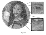
- a security document generated by such a method takes the form of a halftone image rendered with a line-based halftone screen (see Figure 16).
- a third method for embedding the signal in printed images uses a printing process capable of producing stripes with a controllable thickness, such as intaglio printing.
- the security pattern is printed as an overlay on the original image, either by using an additional intaglio plate or by modifying an already existing plate.
- a transparent or a semitransparent ink e.g. a varnish
- a fourth method for embedding the signal in microstructure, digital images consists in applying local modifications to the microstructure. These local modifications have the effect of thickening the microstructure in the parts where the stripes of the pattern are thicker, and they have the effect of thinning the microstructure in the parts where the stripes of the pattern are thinner ( Figure 17). At a macroscopic level, areas with a thickened microstructure have a higher intensity value and areas with a thinned microstructure have lower intensity.
- a fifth method replaces the linear grating image by a circularly symmetric grating image.
- This circularly symmetric grating is obtained by sweeping a one-dimensional signal across a 360-degree arc.
- the property of circular symmetry guarantees that the signal observed along a straight line crossing the grating at its center remains the same for all angles of the line.
- the signal is then embedded using the first, the third or the fourth method. Examples of circularly symmetric signals are provided in Figure 22, Figure 24, Figure 26 and Figure 28.
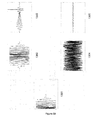
- the 2D signal is built by sweeping the auto-correlated 1 D signal depicted in Figure 21 along a 360-degree arc.
- the 2D signal is built by sweeping the self-similar 1 D signal depicted in Figure 23 along a 360-degree arc.
- the 2D signal is built by sweeping the scale-invariant 1 D signal depicted in Figure 25 along a 360-degree arc.
- the 2D signal is built by sweeping the scale-invariant 1 D signal depicted in Figure 27 along a 360-degree arc.
- a sixth method for embedding a circularly symmetric grating uses an inverse integral transform.
- the selected inverse integral transform is applied to a pair of components.
- the first component is a module component R; it is generated with a circularly symmetric grating.
- the second component is a phase component P; it is generated with the output of a quantum random number generator (e.g. http://www.randomnumbers.info/) or a pseudo-random number generator.
- the result A* of the inverse Fourier transform of C yields a signal that looks like white noise, but that exhibit the original grating in the frequency domain.
- FIG. 35 shows an example of embedding a circularly symmetric grating in the frequency domain.
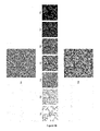
- a Fourier transform (H) is synthesized by combining a module based on a circularly symmetric signal (1201) and a phase based on white noise (1202).
- the inverse Fourier transform of (H) yields a two-dimensional signal (1203) that looks like white noise.
- a seventh method uses a circularly symmetric grating embedded in the frequency domain as a spot function for thresholding a grayscale image.
- a circularly symmetric grating embedded in the frequency domain as a spot function for thresholding a grayscale image.
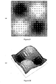
- An example of a three-dimensional representation of a general spot function is shown in Figure 32: the values of the spot function are materialized by steps of varying heights that have a grayscale value corresponding to their height.
- the embedded spot function is then discretized in so as to produce a dither matrix that can be used to threshold a grayscale image in order to generate a bilevel halftone image.
- FIG. 31 An example of a dither matrix is shown in Figure 31: a first representation is given by an array of numerical thresholds that are uniformly distributed between 0 and 255, and a second representation of the same dither matrix is given by an array of grayscale values that correspond to the numerical thresholds of the first representation.
- Figure 33 shows another example of a dither matrix (901) represented as an array of grayscale values; this dither matrix is used to threshold a linear grayscale gradation in order to produce a bilevel halftone gradation (902).
- the size of the dither matrix may be adapted to the size of the circularly symmetric pattern by building a second, larger dither matrix as a tiling of the first dither matrix, as shown in Figure 34.
- FIG. 35 shows an example of using a two-dimensional signal (1203) as a spot function in order to threshold a linear grayscale gradation in order to produce a bilevel halftone gradation (1204).
- An eighth method builds an embedded spot function based on a signal A* constructed with the fifth method.
- the continuous signal A* is thresholded in order to produce an array B of black and white pixels.
- the array B is duplicated so as to produce identical copies ⁇ B 1 , B 2 , ... B n ⁇ .
- Figure 36 shows an example of morphological operations applied to a discretized spot function.
- a square area (601) of the spot function (1203) depicted in Figure 35 is thresholded (602) so that half its elements are black and the other half are white.
- the outlines of this bitmap are shown in (604).
- the skeleton of the same bitmap is shown in (606).
- the pruned skeleton of the same bitmap is shown in (608).
- the values of the thresholded bitmap are inverted so as to produce a dual bitmap (603).
- the inverse outlines of this dual bitmap are shown in (605).
- the inverse skeleton of the same dual dual bitmap is shown in (607).
- the inverse pruned skeleton of the same dual bitmap is shown in (609).
- Figure 37 shows the module of the Fourier transform of some of the morphological results depicted in Figure 36.
- the same circularly symmetric pattern is visible with a variable extent and a variable clarity in each one of the transforms (1202), (1204), (1206) and (1208).
- the results of the morphological operations ⁇ M 1 , M 2 , ...
- M n ⁇ are ranked according to their ratio of black pixels K k /N k .
- the black pixels are replaced by the value K k /N k .
- all the M k are merged together to form a spot function S.
- the ranking of the morphological steps (702-708) and their merging into a dither matrix (709) is illustrated in Figure 38. After the merging, the dither matrix can be further enhanced in order to obtain an equilibrated dither matrix.
- Such an enhancement can take the form of weighted histogram equalization, or a slight Gaussian blur, or the addition of a small amount of noise.
- a dither matrix based on morphological operations is used to threshold a linear grayscale gradation in order to produce a bilevel halftone gradation.
- a ninth method builds an embedded spot function by combining a general spot function and a circularly symmetric pattern in the frequency domain.
- Figure 40 shows the construction of such a combined spot function.
- the general spot function is embodied by the tiling (1001) of multiple copies of a simple spot function traditionally used to generate clustered-dot, amplitude-modulation halftone screens (1002).
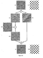
- This tiling is transposed to the frequency domain by the means of a Fourier transform (F), and the result of this Fourier transform is then decomposed into a module component (1003) and a phase component (1004).
- a circularly symmetric pattern (1005) is combined with the module component by the means of a linear interpolation (I).
- the combined module component (1006) is merged back with the phase component (1004) using an inverse Fourier transform (H).
- H inverse Fourier transform
- the result of this inverse Fourier transform undergoes a histogram equalization so as to produce a balanced spot function (1007).
- this spot function is used to threshold a grayscale patch of constant value in order to produce a bilevel halftone patch (1008).
- the above methods are not limited to a circularly symmetric grating of Fourier module; it can also be applied with any pattern obtained by sweeping a particular 1 D signal in an integral transform domain.
- a tenth method produces a dither matrix in the spatial domain by using a balanced, circularly symmetric pattern as a spot function.
- Figure 41 illustrates this method with a bilevel halftone image generated by using a LRHF as spot function in order to threshold a linear grayscale gradation.
- An eleventh method combines two or more spot functions generated with the tenth method in order to produce a new spot function.
- Combination schemes include arithmetic operations such as addition, subtraction and multiplication, N-cyclical group operations such as addition modulo N, subtraction modulo N and multiplication modulo N, geometric operations such as translation, scaling and rotation, and logical operations such as OR, AND and XOR.
- Figure 42 illustrates this method with a bilevel halftone image generated by using a spot function based on the combination of two circularly symmetric patterns.
- the patterns used in this example are a LRHF and a translation of the same LRHF.
- the combination scheme used is an addition modulo 256.
- the embedded pattern is typically recovered after its print-out.
- a digital imaging device like a digital scanner or a camera for instance
- the patte*rn is designed in such a way that it is possible to trigger detection with a mono-dimensional signal processing performed along a straight line having an arbitrary direction across the pattern, for any scale and rotation transformations (in a previously defined range).
- Two issues have to be addressed in order to obtain this result: the reliability of the detection trigger (false-positive and false-negative detections) and the robustness to geometrical transforms.
- the reliability of the detection basically relies on a statistical test. This test must be performed on a sufficiently large set of data in order to reach the desired false-positive (signal detected while not being present) and false-negative performance (signal not detected while being present). In the targeted application, the false-positive rate is expected to reach 1 over 10 millions or better.
- the statistical data can be processed during the digitization or during the printing process. Since the detection approach relies on a 1 dimensional signal processing, it may also be performed in real-time as data is streamed into the hardware into which the detection is performed.
- the robustness to geometrical transforms can be achieved using two different approaches.
- One solution is to have a signal that is invariant with affine transformations; the other solution is to compensate for the transformation before decoding the signal.
- the pattern is designed so that the 1 D profile of the pattern taken in any direction and with any scale, exhibits an invariant feature. This similar feature can then be used to trigger the detection, disregarding the geometrical transform which has been applied to the image.
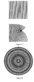
- Figure 12 shows an example of a pattern exhibiting an invariant feature: this pattern is composed of concentric circles. Any straight line crossing this pattern through its center will produce the same 1D profile.
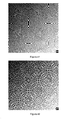
- Figure 16 shows a pattern exhibiting an invariant feature embedded into an image under the form of a halftone screen composed of concentric circles.
- Invariance under rotation can also be obtained by embedding a circularly symmetric pattern in the Fourier domain.
- image data is transferred through the device one line at a time.
- the detector applies a color transform to the individual image lines in order to transpose them into the color space where the security image is present.
- the sum S of the transformed lines is stored in a separate image buffer. This sum can be viewed as the projection of the image from a two-dimensional space onto a one-dimensional space.
- the detector calculates the one-dimensional Fourier transform FS of the sum S.
- the result of this Fourier transform is individually compared to a bank of predetermined one-dimensional signal templates stored in the device's ROM.
- steps include windowing (Hamming), pre-whitening, band-pass filtering, histogram equalization, envelope demodulation, denoising, windowed averaging.
- Windowing Hamming
- pre-whitening a few lines
- band-pass filtering a few lines
- histogram equalization a measure of envelope demodulation
- denoising averaging of windowed averaging.
- the result of the comparison between FS and the device's bank of one-dimensional signal templates is assessed with the help of one or more statistical tests. If the assessment yields a positive answer, the image is assumed to carry the security image and the device reacts accordingly by interrupting its function.
- This process may also be performed in several steps: a first step using a few lines to detect if the signal is present. If the signal is detected then additional lines are processed in order to confirm the detection (this approach enables to satisfy false-positive requirements and processing speed requirements). Data of successive lines may also be used to compute a signal in a rotated direction. This also contributes to reach
- Figure 46 shows another radially symmetric pattern generated by subdividing a scale-invariant pattern (LRHF) in 360 sectors of 1 degree of arc and by applying a random radial jitter to each sector.
- Compensation can be performed either by using a separate reference pattern (for instance a printed circular pattern enables to define the horizontal versus vertical scale alteration) or by a mathematical transform of the signal that maps it into another domain in which the compensation is performed more easily. For instance, a logarithmic transform enables to map the signal in a different space that allows for easy compensation of a scale alteration.
- This scaling can be caused for instance by a digitizing resolution that is different from the printing resolution of the signal. It may also be caused by a rotation of the digitized sample as shown in Figure 18.
- the scaling factor is related to the angle of rotation a with the cosine function Cos(a).
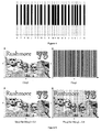
- the statistical test is performed in the simplest embodiment as a finite state machine which counts how many times the signal matches some predefined characteristics and compares it to a threshold. These characteristics can be a number of transitions of the signal, a sequence of width as shown in Figure 4 or a sequence of spacing as shown in Figure 3.
- the signal is then defined as a grayscale value.
- the signal is a vector defined by several color components, for instance red-green-blue, cyan-magenta-yellow-black, hue-luminance-saturation, hue-saturation-value, CIE-Lab, CIE-Lch or CIE-XYZ (or in certain predefined range of light wavelength). This multi-color approach enables to increase the detection rate performances.
- the detected characteristics are defined by a quantum random number generator or a pseudo-random number generator with a key provided separately or computed from other features (visual or not) of the security document.
- the statistical test is performed using signal processing algorithms (for instance but not limited to cross-correlation, invariant computation, etc). The result of this test is then compared to some pre-defined threshold or threshold computed from the processed data.
- signal processing algorithms for instance but not limited to cross-correlation, invariant computation, etc.
- the robustness to geometrical attacks can be performed in one embodiment by the mean of an invariant feature, including but not limited to, circular patterns.
- the robustness is obtained using a compensation method.
- this method uses the above described Log transform combined with some cross-correlation (or other matching indicator) technique.
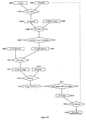
- the general detection scheme is shown in Figure 20: In 2600, colors of the banknote are digitally sampled along a straight line across the banknote (and titled with an arbitrary angle) and stored as a 1 D signal. In 2601, a filtering may be performed in order to enhance some particular properties. In 2602, a statistical test is then performed.
- This test can be based for instance on the cross-correlation with a 1 D signal, or an autocorrelation, a measurement of auto-similarities, etc. Such measurements are generically named "correlation" throughout this document.
- this values corresponding to this measurement is accumulated with values computed for previous lines and compared to one or several thresholds. If the accumulated values exceed some threshold, a positive detection signal is sent in 2604. In case of no positive detection, the system acquires a new line of the banknote in 2605.
- the detection of the security image may also use one-dimensional signal processing based on Fourier transform. Its theoretical basis lies on a result from the field of tomographic reconstruction, the projection-slice theorem.
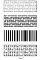
- the security pattern that is applied by the first method takes the form of a linear grating of alternating dark and light stripes ( Figure 1).
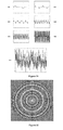
- This grating incorporates a square-pulse signal ( Figure 2) which is carried by the modulation of the distance between the centers of the stripes ( Figure 3) or by the modulation of the width of the stripes ( Figure 4).
- the value of the stripes varies continuously along their width.
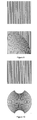
- the shape of the signal carried by the security pattern takes the form of a continuous function like a sine wave ( Figure 6) or a triangle pulse ( Figure 7).
- the pattern undergoes a geometrical transform under the form of a conformal mapping ( Figure 8, Figure 9, Figure 10, Figure 11).
- a geometrical transform produces a pattern formed of concentric circles ( Figure 12).
- Such a pattern exhibits an invariant feature: the same signal can be detected across all the straight lines crossing the pattern through its center, regardless of their orientation.
- Such an invariant feature enables the detection approach based on an invariant signal.
- the original image is divided in several separate areas and the security document is obtained by embedding a different security pattern in each area.
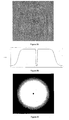
- the security document is obtained by separately embedding a different security pattern into in each color component of the original color image ( Figure 14).
- RGB images embedded in the B component CIE-Lab images embedded in the L component, CMYK images embedded in the Y component, etc.
- the security document is obtained by transforming the color space of the original image before embedding the pattern into a subset of the transformed color components.
- RGB -> HLS embedding in the H component
- RGB -> CIE-Lch embedding in the c component
- the security pattern is embedded in the security document by modifying only the chrominance components of the original image.
- the original luminance component is left unmodified, and the difference between the original chrominance components and the modified chrominance components is maintained below the perceptual threshold.
- one security pattern is generated for every luminance level present in the original image.
- the thickness of the lines of these patterns varies accordingly to the luminance level they are associated to, but the position of these lines remains constant across each one of the patterns ( Figure 15).
- the security document is then obtained from these security patterns by embedding them under the form of a halftone screen ( Figure 16). Using a circular pattern (like the example shown in Figure 16) enables to obtain a signal that is invariant to rotation.
- the security pattern is an invariant signal which is defined in the Fourier domain.
- a security image layer is built from the security pattern by the means of an inverse Fourier transform.
- the security image C(x,y) A(x,y) * exp(i * B(x,y)) defined above in the Fourier domain with a rotating 1 D function for A(x,y) and a quantum random signal or a pseudo-random signal for B(x,y) is directly printed as an overlay on the banknote to be protected.
- a banknote is first printed with 4 different ink colors.
- the security image (see image 1203 in Figure 35) layer is afterward overlaid with a separate color all over the already printed banknote. This color should be chosen in order to obtain the best compromise between invisibility and detectability of the signal. For instance, a light gray color may be an appropriate choice for a banknote featuring little or no graphic (like in the water mark area). A darker ink may be required in other cases.
- the color of the security image should be chosen among the already used set of colors (4 in our example) in order to minimize the number of offset plates.
- the main problem that arises when overlaying over a non uniform area like a banknote is to obtain areas where the security image is either too visible (thus degrading the visual appearance of the banknote) or not enough visible (thus not reliably detectable).
- One solution is to locally increase or decrease the intensity of the security image based on a weighting function W(x,y) as shown in the first embodiment.
- Another solution consists in adjusting the transparency of the ink used for producing the signal overlay: a transparent ink will produce a faintly visible signal on all but the lightest backgrounds, while an opaque ink will produce a strongly visible signal on most backgrounds.
- the security pattern is obtained by combining the fourth and ninth embodiment: a banknote includes some areas with a grating and other areas filled with an invariant signal.
- the integration of the signal into the design layout of the banknote can be performed as illustrated in Figure 49:
- the signal is digitally injected into the artwork 2511 (either by modifying the dither matrices or by digital overlay) of the banknote with a strength 2510.
- an estimate of the signal intensity is computed. This estimate is a prediction of what will be the signal intensity after printing and scanning and is compared to some predefined threshold in 2502 (this threshold can be the minimum number of lines required for a positive detection). If intensity is not sufficient, then strength 2510 is increased and the process repeats. The whole process may be entirely automatic (the system automatically adjusts to the minimum strength required for positive detection) or interactive (the designer can then evaluate the visual impact of a given strength on the design and on the detectability). This adjustment process may be non-iterative if it is possible to predict exactly the strength required for a given artwork 2511.
Landscapes
- Engineering & Computer Science (AREA)
- Physics & Mathematics (AREA)
- General Physics & Mathematics (AREA)
- Computer Security & Cryptography (AREA)
- Theoretical Computer Science (AREA)
- Editing Of Facsimile Originals (AREA)
- Image Processing (AREA)
- Facsimile Image Signal Circuits (AREA)
- Inspection Of Paper Currency And Valuable Securities (AREA)
Claims (22)
- Verfahren zur Erzeugung eines Sicherheitsdruckbildes auf einer Banknote, wobei das Druckbild ein Originalbild und ein Sicherheitsmuster (1008) umfasst, dadurch gekennzeichnet, dass das Sicherheitsmuster in der Raumdomäne durch eine inverse Fourier-Transformation (1007) aus der Kombination der Fourier-Transformation (1003, 1004) eines Hilfsdruckbildes (1002) und eines zweidimensionalen, radialsymmetrischen Musters in der Frequenzdomäne gewonnen wird und das zweidimensionale Muster erzeugt wird, indem mit einer eindimensionalen selbstähnlichen Funktion (201 - 206) ein Bogen von 360 Grad derart überstrichen wird, dass das Sicherheitsmuster vom Maximalwert der Kreuzkorrelation (1303, 1305) der eindimensionalen Funktion (1301) mit der Fourier-Transformation einer Linie (1302, 1304) der Banknote aus erkennbar ist, wobei die Linie mit einer beliebigen Auflösung zwischen 50 und 1200 Punkten pro Zoll entlang einer beliebigen Richtung abgetastet wird und das Sicherheitsdruckbild in der Raumdomäne durch Verschmelzung zumindest einer Farbe zumindest eines Teils des Originalbildes mit dem Sicherheitsmuster erzeugt wird.
- Verfahren, wie in Anspruch 1 definiert und dadurch gekennzeichnet, dass der Modul der Fourier-Transformation des Sicherheitsmusters ein zweidimensionales, radialsymmetrisches Muster enthält.
- Verfahren, wie in Anspruch 1 definiert und dadurch gekennzeichnet, dass die Verschmelzung des Originalbildes mit dem Sicherheitsmuster zur Erzeugung des Sicherheitsdruckbildes durch ein Thresholding von Graustufenbildern mit einer Spotfunktion erfolgt, wobei der Modul der Fourier-Transformation der Spotfunktion ein zweidimensionales, radialsymmetrisches Muster enthält.
- Verfahren, wie in Anspruch 3 definiert und dadurch gekennzeichnet, dass die Spotfunktion als die inverse Fourier-Transformation eines Moduls und einer Phase konstruiert wird, wobei der Modul ein radialsymmetrisches Muster und die Phase ein weisses Rauschen ist.
- Verfahren, wie in Anspruch 3 definiert und dadurch gekennzeichnet, dass die Spotfunktion als die inverse Fourier-Transformation eines Moduls und einer Phase konstruiert wird, wobei der Modul als eine lineare Interpolation zwischen einem Paar von zweidimensionalen Mustern konstruiert wird, das erste Muster ein kreissymmetrisches Muster ist, das durch Überstreichen eines Bogens von 360 Grad mit einem eindimensionalen, selbstähnlichen Signal konstruiert wird, und das zweite Muster der Modul der Fourier-Transformation einer willkürlichen Spotfunktion ist, während die Phase die Phase der Fourier-Transformation der willkürlichen Spotfunktion ist.
- Verfahren nach Ansprüchen 2 bis 5, dadurch gekennzeichnet, dass das zweidimensionale, radialsymmetrische Muster auch kreissymmetrisch ist und durch Überstreichen eines Bogens von 360 Grad mit einem eindimensionalen Signal konstruiert wird.
- Verfahren nach Anspruch 6, dadurch gekennzeichnet, dass das zweidimensionale, kreissymmetrische Muster durch Überstreichen eines Bogens von 360 Grad mit einem eindimensionalen, autokorrelierten Signal konstruiert wird.
- Verfahren nach Anspruch 6, dadurch gekennzeichnet, dass das zweidimensionale, kreissymmetrische Muster durch Überstreichen eines Bogens von 360 Grad mit einem eindimensionalen, massstab-invarianten Signal konstruiert wird.
- Verfahren nach Ansprüchen 2 oder 3, dadurch gekennzeichnet, dass der Modul der Fourier-Transformation des Sicherheitsdruckbildes ein zweidimensionales, radialsymmetrisches Muster enthält, das durch Überstreichen einer radialsymmetrischen Kurve mit einem eindimensionalen, autokorrelierten Signal konstruiert wird.
- Verfahren nach Ansprüchen 2 oder 3, dadurch gekennzeichnet, dass der Modul der Fourier-Transformation des Sicherheitsdruckbildes ein zweidimensionales, radialsymmetrisches Muster enthält, das durch Überstreichen einer radialsymmetrischen Kurve mit einem eindimensionalen, massstab-invarianten Signal konstruiert wird.
- Verfahren nach Anspruch 3, dadurch gekennzeichnet, dass der Modul der Fourier-Transformation der Spotfunktion ein zweidimensionales, radialsymmetrisches Muster enthält, das durch Überstreichen einer radialsymmetrischen Kurve mit einem eindimensionalen, autokorrelierten Signal konstruiert wird.
- Verfahren nach Anspruch 3, dadurch gekennzeichnet, dass der Modul der Fourier-Transformation der Spotfunktion ein zweidimensionales, radialsymmetrisches Muster enthält, das durch Überstreichen einer radialsymmetrischen Kurve mit dem eindimensionalen, massstab-invarianten Signal konstruiert wird.
- Verfahren, wie in Anspruch 1 definiert und dadurch gekennzeichnet, dass das Sicherheitsdruckbild verdeckt ist.
- Verfahren, wie in Anspruch 1 definiert und dadurch gekennzeichnet, dass das Sicherheitsdruckbild eine dekorative Funktion ausfüllt.
- Verfahren, wie in Anspruch 1 definiert und dadurch gekennzeichnet, dass mehrfache Sicherheitsdruckbilder verwendet werden, die mit unterschiedlichen Sweep-Kurven erzeugt werden.
- Verfahren, wie in Anspruch 1 definiert und dadurch gekennzeichnet, dass mehrfache Sicherheitsdruckbilder verwendet werden, die mit unterschiedlichen eindimensionalen Signalen erzeugt werden.
- Verfahren, wie in Anspruch 1 definiert und dadurch gekennzeichnet, dass mehrfache Sicherheitsdruckbilder verwendet werden, die mit untrerschiedlichen Verschmelzungstechniken erzeugt werden.
- Verfahren, wie in Anspruch 1 definiert und dadurch gekennzeichnet, dass die Verschmelzungstechnik eine Überlagerung des Originalbildes mit dem Sicherheitsdruckbild ist.
- Verfahren, wie in Anspruch 1 definiert und dadurch gekennzeichnet, dass die Verschmelzungstechnik eine Überlagerung des Sicherheitsdruckbildes mit dem Originalbild ist.
- Verfahren, wie in Ansprüchen 18 und 19 definiert und dadurch gekennzeichnet, dass die Überlagerung zweier Bilder erfolgt, indem das erste Bild auf das zweite aufgedruckt wird.
- Verfahren, wie in Anspruch 1 definiert und dadurch gekennzeichnet, dass das Sicherheitsmuster auch durch eine Kombination aufeinander folgender Linien identifiziert werden kann.
- Verfahren, wie in Anspruch 1 definiert und dadurch gekennzeichnet, dass die Erkennung durch eine Kombination aufeinander folgender Linien erfolgt.
Priority Applications (3)
| Application Number | Priority Date | Filing Date | Title |
|---|---|---|---|
| SI200530204T SI1714246T1 (sl) | 2005-02-15 | 2005-10-12 | Bankovci z natisnjeno varnostno sliko, ki se jo lahko zazna z obdelavo enodimenzionalnih signalov |
| PL05796937T PL1714246T3 (pl) | 2005-02-15 | 2005-10-12 | Banknoty z drukowanym obrazem zabezpieczającym, który może być wykryty przez przetwarzanie sygnału jednowymiarowego |
| EP05796937A EP1714246B1 (de) | 2005-02-15 | 2005-10-12 | Banknoten mit einem aufgedruckten sicherheitsbild, das mit eindimensionaler signalverarbeitung erkannt werden kann |
Applications Claiming Priority (3)
| Application Number | Priority Date | Filing Date | Title |
|---|---|---|---|
| EP05101116A EP1691539A1 (de) | 2005-02-15 | 2005-02-15 | Zweidimensional-Sicherheitsmuster auf Echtheit bescheinigbar mit Eindimensional-Signalverarbeitung |
| EP05796937A EP1714246B1 (de) | 2005-02-15 | 2005-10-12 | Banknoten mit einem aufgedruckten sicherheitsbild, das mit eindimensionaler signalverarbeitung erkannt werden kann |
| PCT/EP2005/055204 WO2006048368A1 (en) | 2005-02-15 | 2005-10-12 | Banknotes with a printed security image that can be detected with one-dimensional signal processing |
Publications (2)
| Publication Number | Publication Date |
|---|---|
| EP1714246A2 EP1714246A2 (de) | 2006-10-25 |
| EP1714246B1 true EP1714246B1 (de) | 2008-01-09 |
Family
ID=34938736
Family Applications (2)
| Application Number | Title | Priority Date | Filing Date |
|---|---|---|---|
| EP05101116A Withdrawn EP1691539A1 (de) | 2005-02-15 | 2005-02-15 | Zweidimensional-Sicherheitsmuster auf Echtheit bescheinigbar mit Eindimensional-Signalverarbeitung |
| EP05796937A Expired - Lifetime EP1714246B1 (de) | 2005-02-15 | 2005-10-12 | Banknoten mit einem aufgedruckten sicherheitsbild, das mit eindimensionaler signalverarbeitung erkannt werden kann |
Family Applications Before (1)
| Application Number | Title | Priority Date | Filing Date |
|---|---|---|---|
| EP05101116A Withdrawn EP1691539A1 (de) | 2005-02-15 | 2005-02-15 | Zweidimensional-Sicherheitsmuster auf Echtheit bescheinigbar mit Eindimensional-Signalverarbeitung |
Country Status (14)
| Country | Link |
|---|---|
| US (1) | US7991186B2 (de) |
| EP (2) | EP1691539A1 (de) |
| JP (1) | JP5009169B2 (de) |
| AT (1) | ATE383624T1 (de) |
| AU (1) | AU2005300589B2 (de) |
| CA (1) | CA2597088C (de) |
| DE (1) | DE602005004263T2 (de) |
| DK (1) | DK1714246T3 (de) |
| ES (1) | ES2301067T3 (de) |
| NO (1) | NO20074145L (de) |
| PL (1) | PL1714246T3 (de) |
| PT (1) | PT1714246E (de) |
| SI (1) | SI1714246T1 (de) |
| WO (1) | WO2006048368A1 (de) |
Cited By (1)
| Publication number | Priority date | Publication date | Assignee | Title |
|---|---|---|---|---|
| WO2009121141A1 (en) * | 2008-04-03 | 2009-10-08 | Commonwealth Scientific And Industrial Research Organisation | A hidden image method and a hidden image apparatus |
Families Citing this family (41)
| Publication number | Priority date | Publication date | Assignee | Title |
|---|---|---|---|---|
| US7555139B2 (en) | 1995-05-08 | 2009-06-30 | Digimarc Corporation | Secure documents with hidden signals, and related methods and systems |
| US6978036B2 (en) | 1998-07-31 | 2005-12-20 | Digimarc Corporation | Tamper-resistant authentication techniques for identification documents |
| US7974495B2 (en) | 2002-06-10 | 2011-07-05 | Digimarc Corporation | Identification and protection of video |
| US8181884B2 (en) | 2003-11-17 | 2012-05-22 | Digimarc Corporation | Machine-readable features for objects |
| JP4555212B2 (ja) * | 2005-11-10 | 2010-09-29 | 株式会社沖データ | 透かし情報埋め込み装置,透かし情報埋め込み方法,およびコンピュータプログラム |
| US7889885B2 (en) * | 2005-11-23 | 2011-02-15 | Pitney Bowes Inc. | Method for detecting perforations on the edge of an image of a form |
| US8096584B2 (en) * | 2006-07-24 | 2012-01-17 | 3M Innovative Properties Company | Document authentication using template matching with fast masked normalized cross-correlation |
| US20090121471A1 (en) * | 2007-01-31 | 2009-05-14 | Gaffney Gene F | Method and system for producing documents, websites, and the like having security features |
| US7740281B2 (en) | 2007-01-31 | 2010-06-22 | The Ergonomic Group | Method and system for producing certified documents and the like |
| TWI373034B (en) * | 2007-05-23 | 2012-09-21 | Chunghwa Picture Tubes Ltd | Pixel dithering driving method and timing controller using the same |
| AU2008258153A1 (en) * | 2008-12-16 | 2010-07-01 | Canon Kabushiki Kaisha | Method for generating alignment marks |
| US9749607B2 (en) | 2009-07-16 | 2017-08-29 | Digimarc Corporation | Coordinated illumination and image signal capture for enhanced signal detection |
| ATE546011T1 (de) * | 2009-09-09 | 2012-03-15 | European Central Bank | Verfahren zur erzeugung eines sicherheitsbildes auf zwei ebenen für banknoten |
| JP4875132B2 (ja) * | 2009-10-29 | 2012-02-15 | シャープ株式会社 | 画像処理装置、画像データ出力処理装置、および画像処理方法 |
| US8639059B2 (en) * | 2010-02-10 | 2014-01-28 | Andrew Batrac | Method for lossless digital shearing and rotation with fine angular increments |
| WO2013179249A1 (en) * | 2012-05-30 | 2013-12-05 | Label Tech International Trims Limited | Authentication apparatus and methods |
| CN103035061B (zh) * | 2012-09-29 | 2014-12-31 | 广州广电运通金融电子股份有限公司 | 有价文件防伪特征生成方法及其鉴别方法和装置 |
| CN102914810A (zh) * | 2012-10-11 | 2013-02-06 | 武汉华工图像技术开发有限公司 | 一种基于莫尔条纹技术的全息母版制作方法及全息图 |
| US9635378B2 (en) | 2015-03-20 | 2017-04-25 | Digimarc Corporation | Sparse modulation for robust signaling and synchronization |
| US10424038B2 (en) | 2015-03-20 | 2019-09-24 | Digimarc Corporation | Signal encoding outside of guard band region surrounding text characters, including varying encoding strength |
| EP3016063A1 (de) * | 2014-11-03 | 2016-05-04 | Thomson Licensing | Verfahren und Vorrichtung zum Bedrucken, unter Verwendung einer Maske, von Bildinhalt innerhalb eines Originalbildes ohne Änderung des Y-Werts der durch dieses Bedrucken betroffenen Pixel |
| US10783601B1 (en) | 2015-03-20 | 2020-09-22 | Digimarc Corporation | Digital watermarking and signal encoding with activable compositions |
| US9754341B2 (en) | 2015-03-20 | 2017-09-05 | Digimarc Corporation | Digital watermarking and data hiding with narrow-band absorption materials |
| US9672678B2 (en) * | 2015-06-15 | 2017-06-06 | Datalogic Usa, Inc. | Method and system of using image capturing device for counterfeit article detection |
| CN105528583A (zh) * | 2015-12-17 | 2016-04-27 | 清华大学深圳研究生院 | 基于实数形式傅里叶变换的特征提取方法及故障诊断方法 |
| WO2018126187A1 (en) * | 2016-12-30 | 2018-07-05 | Jones Robert L | Embedded variable line patterns |
| EP3563358A4 (de) | 2016-12-30 | 2019-12-25 | Wu, Yecheng | Eingebettete variable linienmuster für bilder |
| US10475846B2 (en) * | 2017-05-30 | 2019-11-12 | Ncr Corporation | Media security validation |
| US10872392B2 (en) | 2017-11-07 | 2020-12-22 | Digimarc Corporation | Generating artistic designs encoded with robust, machine-readable data |
| US10896307B2 (en) | 2017-11-07 | 2021-01-19 | Digimarc Corporation | Generating and reading optical codes with variable density to adapt for visual quality and reliability |
| US11062108B2 (en) | 2017-11-07 | 2021-07-13 | Digimarc Corporation | Generating and reading optical codes with variable density to adapt for visual quality and reliability |
| US20190213705A1 (en) | 2017-12-08 | 2019-07-11 | Digimarc Corporation | Artwork generated to convey digital messages, and methods/apparatuses for generating such artwork |
| CN108615218B (zh) * | 2018-05-02 | 2022-02-15 | 北京印刷学院 | 伪随机信息空域调制的印刷量子点水印检测方法 |
| CN108777805B (zh) * | 2018-05-17 | 2021-01-22 | 北京奇艺世纪科技有限公司 | 一种非法访问请求的检测方法、装置、中控服务器及系统 |
| WO2019237045A1 (en) | 2018-06-08 | 2019-12-12 | Digimarc Corporation | Generating signal bearing art using stipple, voronoi and delaunay methods and reading same |
| US11055805B1 (en) * | 2018-11-09 | 2021-07-06 | Digimarc Corporation | Utilizing dependency between watermark visibility and location of image sample in color space for embedded signal color direction |
| US10916037B2 (en) | 2018-12-13 | 2021-02-09 | Canon Kabushiki Kaisha | Method of encoding and decoding calibration marker identifiers |
| CN110956737B (zh) * | 2020-01-07 | 2021-10-12 | 武汉卓目科技有限公司 | 一种安全线识别方法和装置 |
| US12333624B1 (en) | 2021-06-04 | 2025-06-17 | Digimarc Corporation | Modulating surface topcoats to embed digital watermarking |
| DE102021125567A1 (de) | 2021-10-01 | 2023-04-06 | Mühlbauer ID Services GmbH | Sicherheitslösung mit einem verfahren und einer vorrichtung zur verifikation eines digitalen bilds mit integriertem sicherheitsmerkmal |
| PL441418A1 (pl) * | 2022-06-08 | 2023-12-11 | Polska Wytwórnia Papierów Wartościowych Spółka Akcyjna | Sposób zabezpieczania nośnika danych, sposób automatycznego progowania, element zabezpieczający oraz nośnik danych |
Family Cites Families (38)
| Publication number | Priority date | Publication date | Assignee | Title |
|---|---|---|---|---|
| US669041A (en) * | 1900-05-11 | 1901-02-26 | Hugh B Copeland | Portable wall. |
| US5018767A (en) * | 1989-01-18 | 1991-05-28 | Schmeiser, Morelle & Watts | Counterfeit protected document |
| US5784200A (en) * | 1993-05-27 | 1998-07-21 | Dai Nippon Printing Co., Ltd. | Difraction grating recording medium, and method and apparatus for preparing the same |
| US6345104B1 (en) * | 1994-03-17 | 2002-02-05 | Digimarc Corporation | Digital watermarks and methods for security documents |
| US6424725B1 (en) | 1996-05-16 | 2002-07-23 | Digimarc Corporation | Determining transformations of media signals with embedded code signals |
| US6449377B1 (en) * | 1995-05-08 | 2002-09-10 | Digimarc Corporation | Methods and systems for watermark processing of line art images |
| US6408082B1 (en) | 1996-04-25 | 2002-06-18 | Digimarc Corporation | Watermark detection using a fourier mellin transform |
| US6549638B2 (en) | 1998-11-03 | 2003-04-15 | Digimarc Corporation | Methods for evidencing illicit use of a computer system or device |
| US6198545B1 (en) | 1994-03-30 | 2001-03-06 | Victor Ostromoukhov | Method and apparatus for generating halftone images by evolutionary screen dot contours |
| GB9413413D0 (en) * | 1994-07-04 | 1994-08-24 | At & T Global Inf Solution | Apparatus and method for testing bank-notes |
| US5995638A (en) | 1995-08-28 | 1999-11-30 | Ecole Polytechnique Federale De Lausanne | Methods and apparatus for authentication of documents by using the intensity profile of moire patterns |
| US6723121B1 (en) | 1997-06-18 | 2004-04-20 | Scimed Life Systems, Inc. | Polycarbonate-polyurethane dispersions for thrombo-resistant coatings |
| US6104812A (en) * | 1998-01-12 | 2000-08-15 | Juratrade, Limited | Anti-counterfeiting method and apparatus using digital screening |
| US6978036B2 (en) * | 1998-07-31 | 2005-12-20 | Digimarc Corporation | Tamper-resistant authentication techniques for identification documents |
| WO2001000560A1 (en) | 1999-06-29 | 2001-01-04 | Lg Chemical Ltd. | Process for preparing aromatic carbonates |
| ATE268969T1 (de) | 1999-07-28 | 2004-06-15 | Orell Fuessli Security Printin | Verfahren zur erzeugung eines sicherheitsdokuments |
| US6760464B2 (en) * | 2000-10-11 | 2004-07-06 | Digimarc Corporation | Halftone watermarking and related applications |
| CH694233A5 (fr) | 2000-09-20 | 2004-09-30 | Alpvision Sa | Procédé d'application et de reconnaissance d'un filigrane numérique surimprimé. |
| ES2356598T3 (es) * | 2000-09-20 | 2011-04-11 | Alpvision Sa | Proceso destinado a prevenir la falsificación o la alteración de una superficie impresa o grabada. |
| US6694041B1 (en) | 2000-10-11 | 2004-02-17 | Digimarc Corporation | Halftone watermarking and related applications |
| US6865273B2 (en) * | 2002-06-05 | 2005-03-08 | Sony Corporation | Method and apparatus to detect watermark that are resistant to resizing, rotation and translation |
| US7602936B2 (en) * | 2001-03-08 | 2009-10-13 | Sony Corporation | Method to make wavelet watermarks resistant to affine transformations |
| US6839450B2 (en) | 2001-04-26 | 2005-01-04 | Hewlett-Packard Development Company, L.P. | Detecting halftone modulations embedded in an image |
| JP2004532735A (ja) | 2001-06-29 | 2004-10-28 | シーメンス アクチエンゲゼルシヤフト | 自動区分装置による送付物の仕分け方法 |
| US20030021437A1 (en) | 2001-07-11 | 2003-01-30 | Hersch Roger David | Images and security documents protected by micro-structures |
| JP4005780B2 (ja) | 2001-07-12 | 2007-11-14 | 興和株式会社 | 電子透かしの埋め込みおよび検出 |
| EP1421705A4 (de) * | 2001-08-07 | 2009-08-05 | Pacific Holographics Inc | System und verfahren zum codieren und decodieren eines bildes oder dokuments und dadurch codiertes dokument |
| JP2003118200A (ja) * | 2001-10-16 | 2003-04-23 | Dainippon Printing Co Ltd | プリンタ出力画像の複写牽制及び偽造防止方法 |
| US6775394B2 (en) | 2002-03-12 | 2004-08-10 | Matsushita Electric Industrial Co., Ltd. | Digital watermarking of binary document using halftoning |
| US7058202B2 (en) * | 2002-06-28 | 2006-06-06 | Ecole polytechnique fédérale de Lausanne (EPFL) | Authentication with built-in encryption by using moire intensity profiles between random layers |
| AU2002951815A0 (en) | 2002-10-03 | 2002-10-24 | Canon Kabushiki Kaisha | Mark embedding and detection using projective transforms |
| AU2003246012B2 (en) | 2002-10-03 | 2005-08-04 | Canon Kabushiki Kaisha | Mark Embedding and Detection Using Projective Transforms |
| US7751608B2 (en) * | 2004-06-30 | 2010-07-06 | Ecole Polytechnique Federale De Lausanne (Epfl) | Model-based synthesis of band moire images for authenticating security documents and valuable products |
| US7194105B2 (en) * | 2002-10-16 | 2007-03-20 | Hersch Roger D | Authentication of documents and articles by moiré patterns |
| US7429062B2 (en) * | 2002-10-30 | 2008-09-30 | Xerox Corporation | Anti-counterfeiting see-through moire security feature using frequency-varying patterns |
| WO2004051917A1 (en) * | 2002-11-28 | 2004-06-17 | Digimarc Corporation | Systems and methods for authentication of print media |
| FR2853748A1 (fr) * | 2003-04-11 | 2004-10-15 | France Telecom | Procede de tatouage d'une image en couleurs par approche vectorielle, procede de detection d'une marque de tatouage, dispositifs, image et programmes d'ordinateurs correspondants |
| US7420709B2 (en) * | 2003-04-30 | 2008-09-02 | Hewlett-Packard Development Company, L.P. | Dither matrix generation |
-
2005
- 2005-02-15 EP EP05101116A patent/EP1691539A1/de not_active Withdrawn
- 2005-10-12 JP JP2007554444A patent/JP5009169B2/ja not_active Expired - Fee Related
- 2005-10-12 WO PCT/EP2005/055204 patent/WO2006048368A1/en not_active Ceased
- 2005-10-12 AT AT05796937T patent/ATE383624T1/de active
- 2005-10-12 CA CA2597088A patent/CA2597088C/en not_active Expired - Fee Related
- 2005-10-12 DK DK05796937T patent/DK1714246T3/da active
- 2005-10-12 PT PT05796937T patent/PT1714246E/pt unknown
- 2005-10-12 EP EP05796937A patent/EP1714246B1/de not_active Expired - Lifetime
- 2005-10-12 ES ES05796937T patent/ES2301067T3/es not_active Expired - Lifetime
- 2005-10-12 DE DE602005004263T patent/DE602005004263T2/de not_active Expired - Lifetime
- 2005-10-12 US US11/816,235 patent/US7991186B2/en active Active
- 2005-10-12 AU AU2005300589A patent/AU2005300589B2/en not_active Ceased
- 2005-10-12 SI SI200530204T patent/SI1714246T1/sl unknown
- 2005-10-12 PL PL05796937T patent/PL1714246T3/pl unknown
-
2007
- 2007-08-10 NO NO20074145A patent/NO20074145L/no not_active Application Discontinuation
Cited By (2)
| Publication number | Priority date | Publication date | Assignee | Title |
|---|---|---|---|---|
| WO2009121141A1 (en) * | 2008-04-03 | 2009-10-08 | Commonwealth Scientific And Industrial Research Organisation | A hidden image method and a hidden image apparatus |
| US8630445B2 (en) | 2008-04-03 | 2014-01-14 | Commonwealth Scientific And Industrial Research Organisation | Hidden image method and hidden image apparatus |
Also Published As
| Publication number | Publication date |
|---|---|
| AU2005300589A1 (en) | 2006-05-11 |
| AU2005300589B2 (en) | 2010-07-29 |
| US7991186B2 (en) | 2011-08-02 |
| EP1691539A1 (de) | 2006-08-16 |
| JP5009169B2 (ja) | 2012-08-22 |
| PT1714246E (pt) | 2008-04-18 |
| ATE383624T1 (de) | 2008-01-15 |
| ES2301067T3 (es) | 2008-06-16 |
| NO20074145L (no) | 2007-09-13 |
| DK1714246T3 (da) | 2008-05-26 |
| WO2006048368A1 (en) | 2006-05-11 |
| DE602005004263D1 (de) | 2008-02-21 |
| CA2597088A1 (en) | 2006-05-11 |
| DE602005004263T2 (de) | 2009-01-22 |
| US20080159615A1 (en) | 2008-07-03 |
| PL1714246T3 (pl) | 2008-06-30 |
| JP2008530666A (ja) | 2008-08-07 |
| CA2597088C (en) | 2014-12-02 |
| SI1714246T1 (sl) | 2008-06-30 |
| EP1714246A2 (de) | 2006-10-25 |
Similar Documents
| Publication | Publication Date | Title |
|---|---|---|
| US7991186B2 (en) | Banknotes with a printed security image that can be detected with one-dimensional signal processing | |
| EP2296362B1 (de) | Verfahren zur Erzeugung eines Sicherheitsbildes auf zwei Ebenen für Banknoten | |
| US8094869B2 (en) | Fragile and emerging digital watermarks | |
| EP1229725B1 (de) | System und Verfahren zur Erzeugung von digitalen Farbwasserzeichen unter Benutzung von konjugierten Halbtonrastern | |
| CA2841146C (en) | Encoding hidden information in spatial line frequencies | |
| JP2012016006A (ja) | デジタルドキュメントへの周波数変調赤外光透かしの埋め込み | |
| US20130172048A1 (en) | Authenticating Identification and Security Documents and Other Objects | |
| KR100864997B1 (ko) | 이미지 처리 방법 및 디바이스 | |
| JP5768236B2 (ja) | 偽造防止用印刷物、偽造防止用印刷物の作製装置及び偽造防止用印刷物の作製方法 | |
| WO2026006828A2 (en) | Copy detection using line art features and encoded signals | |
| JP5990791B2 (ja) | 偽造防止用印刷物 | |
| JP5678364B2 (ja) | 真偽判別可能な印刷物、その作製装置及びその作製方法並びに真偽判別可能な印刷物の認証装置及びその認証方法 | |
| JP4883457B2 (ja) | 印刷物作製方法、印刷物及び真偽判別方法 | |
| US7027613B2 (en) | Digital security image provided with double-banded coding | |
| AU2002228476A1 (en) | Digital security image provided with double-banded coding | |
| Iqbal | High capacity analog channels for smart documents |
Legal Events
| Date | Code | Title | Description |
|---|---|---|---|
| PUAI | Public reference made under article 153(3) epc to a published international application that has entered the european phase |
Free format text: ORIGINAL CODE: 0009012 |
|
| 17P | Request for examination filed |
Effective date: 20060523 |
|
| AK | Designated contracting states |
Kind code of ref document: A2 Designated state(s): AT BE BG CH CY CZ DE DK EE ES FI FR GB GR HU IE IS IT LI LT LU LV MC NL PL PT RO SE SI SK TR |
|
| AX | Request for extension of the european patent |
Extension state: AL BA HR MK YU |
|
| PUAK | Availability of information related to the publication of the international search report |
Free format text: ORIGINAL CODE: 0009015 |
|
| 17Q | First examination report despatched |
Effective date: 20070309 |
|
| GRAP | Despatch of communication of intention to grant a patent |
Free format text: ORIGINAL CODE: EPIDOSNIGR1 |
|
| DAX | Request for extension of the european patent (deleted) | ||
| GRAS | Grant fee paid |
Free format text: ORIGINAL CODE: EPIDOSNIGR3 |
|
| GRAA | (expected) grant |
Free format text: ORIGINAL CODE: 0009210 |
|
| AK | Designated contracting states |
Kind code of ref document: B1 Designated state(s): AT BE BG CH CY CZ DE DK EE ES FI FR GB GR HU IE IS IT LI LT LU LV MC NL PL PT RO SE SI SK TR |
|
| REG | Reference to a national code |
Ref country code: GB Ref legal event code: FG4D |
|
| RIN1 | Information on inventor provided before grant (corrected) |
Inventor name: RUDAZ, NICOLAS Inventor name: JORDAN, FREDERIC Inventor name: GILLES, JEAN-CLAUDEECB Inventor name: KUTTER, MARTIN Inventor name: DURANT, PIERREECB |
|
| REG | Reference to a national code |
Ref country code: CH Ref legal event code: EP |
|
| REG | Reference to a national code |
Ref country code: IE Ref legal event code: FG4D |
|
| REF | Corresponds to: |
Ref document number: 602005004263 Country of ref document: DE Date of ref document: 20080221 Kind code of ref document: P |
|
| REG | Reference to a national code |
Ref country code: PT Ref legal event code: SC4A Free format text: AVAILABILITY OF NATIONAL TRANSLATION Effective date: 20080409 |
|
| REG | Reference to a national code |
Ref country code: SE Ref legal event code: TRGR |
|
| REG | Reference to a national code |
Ref country code: CH Ref legal event code: NV Representative=s name: LEMAN CONSULTING S.A. |
|
| REG | Reference to a national code |
Ref country code: GR Ref legal event code: EP Ref document number: 20080401044 Country of ref document: GR |
|
| REG | Reference to a national code |
Ref country code: DK Ref legal event code: T3 |
|
| REG | Reference to a national code |
Ref country code: ES Ref legal event code: FG2A Ref document number: 2301067 Country of ref document: ES Kind code of ref document: T3 |
|
| REG | Reference to a national code |
Ref country code: PL Ref legal event code: T3 |
|
| PG25 | Lapsed in a contracting state [announced via postgrant information from national office to epo] |
Ref country code: LT Free format text: LAPSE BECAUSE OF FAILURE TO SUBMIT A TRANSLATION OF THE DESCRIPTION OR TO PAY THE FEE WITHIN THE PRESCRIBED TIME-LIMIT Effective date: 20080109 Ref country code: IS Free format text: LAPSE BECAUSE OF FAILURE TO SUBMIT A TRANSLATION OF THE DESCRIPTION OR TO PAY THE FEE WITHIN THE PRESCRIBED TIME-LIMIT Effective date: 20080509 |
|
| ET | Fr: translation filed | ||
| REG | Reference to a national code |
Ref country code: HU Ref legal event code: AG4A Ref document number: E003400 Country of ref document: HU |
|
| PG25 | Lapsed in a contracting state [announced via postgrant information from national office to epo] |
Ref country code: LV Free format text: LAPSE BECAUSE OF FAILURE TO SUBMIT A TRANSLATION OF THE DESCRIPTION OR TO PAY THE FEE WITHIN THE PRESCRIBED TIME-LIMIT Effective date: 20080109 |
|
| PG25 | Lapsed in a contracting state [announced via postgrant information from national office to epo] |
Ref country code: SK Free format text: LAPSE BECAUSE OF FAILURE TO SUBMIT A TRANSLATION OF THE DESCRIPTION OR TO PAY THE FEE WITHIN THE PRESCRIBED TIME-LIMIT Effective date: 20080109 |
|
| PLBE | No opposition filed within time limit |
Free format text: ORIGINAL CODE: 0009261 |
|
| STAA | Information on the status of an ep patent application or granted ep patent |
Free format text: STATUS: NO OPPOSITION FILED WITHIN TIME LIMIT |
|
| PG25 | Lapsed in a contracting state [announced via postgrant information from national office to epo] |
Ref country code: RO Free format text: LAPSE BECAUSE OF FAILURE TO SUBMIT A TRANSLATION OF THE DESCRIPTION OR TO PAY THE FEE WITHIN THE PRESCRIBED TIME-LIMIT Effective date: 20080109 |
|
| 26N | No opposition filed |
Effective date: 20081010 |
|
| PG25 | Lapsed in a contracting state [announced via postgrant information from national office to epo] |
Ref country code: EE Free format text: LAPSE BECAUSE OF FAILURE TO SUBMIT A TRANSLATION OF THE DESCRIPTION OR TO PAY THE FEE WITHIN THE PRESCRIBED TIME-LIMIT Effective date: 20080109 |
|
| PG25 | Lapsed in a contracting state [announced via postgrant information from national office to epo] |
Ref country code: MC Free format text: LAPSE BECAUSE OF NON-PAYMENT OF DUE FEES Effective date: 20081031 |
|
| PG25 | Lapsed in a contracting state [announced via postgrant information from national office to epo] |
Ref country code: CY Free format text: LAPSE BECAUSE OF FAILURE TO SUBMIT A TRANSLATION OF THE DESCRIPTION OR TO PAY THE FEE WITHIN THE PRESCRIBED TIME-LIMIT Effective date: 20080109 |
|
| REG | Reference to a national code |
Ref country code: DE Ref legal event code: R082 Ref document number: 602005004263 Country of ref document: DE Representative=s name: PRINZ & PARTNER PATENTANWAELTE RECHTSANWAELTE, DE Ref country code: DE Ref legal event code: R082 Ref document number: 602005004263 Country of ref document: DE Representative=s name: PRINZ & PARTNER MBB PATENTANWAELTE RECHTSANWAE, DE |
|
| REG | Reference to a national code |
Ref country code: CH Ref legal event code: NV Representative=s name: BUGNION S.A. |
|
| PGFP | Annual fee paid to national office [announced via postgrant information from national office to epo] |
Ref country code: PL Payment date: 20140918 Year of fee payment: 10 Ref country code: LU Payment date: 20141023 Year of fee payment: 10 |
|
| PGFP | Annual fee paid to national office [announced via postgrant information from national office to epo] |
Ref country code: DK Payment date: 20141022 Year of fee payment: 10 |
|
| PGFP | Annual fee paid to national office [announced via postgrant information from national office to epo] |
Ref country code: GR Payment date: 20141014 Year of fee payment: 10 Ref country code: CZ Payment date: 20141007 Year of fee payment: 10 Ref country code: FI Payment date: 20141013 Year of fee payment: 10 Ref country code: SE Payment date: 20141021 Year of fee payment: 10 Ref country code: BG Payment date: 20141013 Year of fee payment: 10 Ref country code: IE Payment date: 20141024 Year of fee payment: 10 |
|
| PGFP | Annual fee paid to national office [announced via postgrant information from national office to epo] |
Ref country code: PT Payment date: 20141010 Year of fee payment: 10 Ref country code: SI Payment date: 20140929 Year of fee payment: 10 Ref country code: HU Payment date: 20141021 Year of fee payment: 10 |
|
| PGFP | Annual fee paid to national office [announced via postgrant information from national office to epo] |
Ref country code: BE Payment date: 20141021 Year of fee payment: 10 |
|
| PGFP | Annual fee paid to national office [announced via postgrant information from national office to epo] |
Ref country code: TR Payment date: 20131012 Year of fee payment: 9 |
|
| REG | Reference to a national code |
Ref country code: FR Ref legal event code: PLFP Year of fee payment: 11 |
|
| REG | Reference to a national code |
Ref country code: PT Ref legal event code: MM4A Free format text: LAPSE DUE TO NON-PAYMENT OF FEES Effective date: 20160412 |
|
| REG | Reference to a national code |
Ref country code: DK Ref legal event code: EBP Effective date: 20151031 |
|
| PG25 | Lapsed in a contracting state [announced via postgrant information from national office to epo] |
Ref country code: LU Free format text: LAPSE BECAUSE OF NON-PAYMENT OF DUE FEES Effective date: 20151012 |
|
| REG | Reference to a national code |
Ref country code: SE Ref legal event code: EUG |
|
| REG | Reference to a national code |
Ref country code: GR Ref legal event code: ML Ref document number: 20080401044 Country of ref document: GR Effective date: 20160506 |
|
| REG | Reference to a national code |
Ref country code: IE Ref legal event code: MM4A |
|
| PG25 | Lapsed in a contracting state [announced via postgrant information from national office to epo] |
Ref country code: GR Free format text: LAPSE BECAUSE OF NON-PAYMENT OF DUE FEES Effective date: 20160506 Ref country code: CZ Free format text: LAPSE BECAUSE OF NON-PAYMENT OF DUE FEES Effective date: 20151012 |
|
| REG | Reference to a national code |
Ref country code: SI Ref legal event code: KO00 Effective date: 20160630 |
|
| PG25 | Lapsed in a contracting state [announced via postgrant information from national office to epo] |
Ref country code: SE Free format text: LAPSE BECAUSE OF NON-PAYMENT OF DUE FEES Effective date: 20151013 Ref country code: HU Free format text: LAPSE BECAUSE OF NON-PAYMENT OF DUE FEES Effective date: 20151013 Ref country code: PT Free format text: LAPSE BECAUSE OF NON-PAYMENT OF DUE FEES Effective date: 20160412 Ref country code: SI Free format text: LAPSE BECAUSE OF NON-PAYMENT OF DUE FEES Effective date: 20151013 |
|
| REG | Reference to a national code |
Ref country code: FR Ref legal event code: PLFP Year of fee payment: 12 |
|
| PG25 | Lapsed in a contracting state [announced via postgrant information from national office to epo] |
Ref country code: DK Free format text: LAPSE BECAUSE OF NON-PAYMENT OF DUE FEES Effective date: 20151031 Ref country code: BG Free format text: LAPSE BECAUSE OF NON-PAYMENT OF DUE FEES Effective date: 20160630 Ref country code: IE Free format text: LAPSE BECAUSE OF NON-PAYMENT OF DUE FEES Effective date: 20151012 |
|
| PG25 | Lapsed in a contracting state [announced via postgrant information from national office to epo] |
Ref country code: PL Free format text: LAPSE BECAUSE OF NON-PAYMENT OF DUE FEES Effective date: 20151012 |
|
| PG25 | Lapsed in a contracting state [announced via postgrant information from national office to epo] |
Ref country code: FI Free format text: LAPSE BECAUSE OF NON-PAYMENT OF DUE FEES Effective date: 20151012 |
|
| PG25 | Lapsed in a contracting state [announced via postgrant information from national office to epo] |
Ref country code: BE Free format text: LAPSE BECAUSE OF NON-PAYMENT OF DUE FEES Effective date: 20151031 |
|
| PG25 | Lapsed in a contracting state [announced via postgrant information from national office to epo] |
Ref country code: TR Free format text: LAPSE BECAUSE OF NON-PAYMENT OF DUE FEES Effective date: 20151012 |
|
| REG | Reference to a national code |
Ref country code: FR Ref legal event code: PLFP Year of fee payment: 13 |
|
| REG | Reference to a national code |
Ref country code: FR Ref legal event code: PLFP Year of fee payment: 14 |
|
| PGFP | Annual fee paid to national office [announced via postgrant information from national office to epo] |
Ref country code: NL Payment date: 20191021 Year of fee payment: 15 |
|
| PGFP | Annual fee paid to national office [announced via postgrant information from national office to epo] |
Ref country code: CH Payment date: 20191021 Year of fee payment: 15 |
|
| PGFP | Annual fee paid to national office [announced via postgrant information from national office to epo] |
Ref country code: GB Payment date: 20191021 Year of fee payment: 15 |
|
| REG | Reference to a national code |
Ref country code: CH Ref legal event code: PL |
|
| REG | Reference to a national code |
Ref country code: NL Ref legal event code: MM Effective date: 20201101 |
|
| GBPC | Gb: european patent ceased through non-payment of renewal fee |
Effective date: 20201012 |
|
| PG25 | Lapsed in a contracting state [announced via postgrant information from national office to epo] |
Ref country code: NL Free format text: LAPSE BECAUSE OF NON-PAYMENT OF DUE FEES Effective date: 20201101 |
|
| PG25 | Lapsed in a contracting state [announced via postgrant information from national office to epo] |
Ref country code: CH Free format text: LAPSE BECAUSE OF NON-PAYMENT OF DUE FEES Effective date: 20201031 Ref country code: GB Free format text: LAPSE BECAUSE OF NON-PAYMENT OF DUE FEES Effective date: 20201012 Ref country code: LI Free format text: LAPSE BECAUSE OF NON-PAYMENT OF DUE FEES Effective date: 20201031 |
|
| PGFP | Annual fee paid to national office [announced via postgrant information from national office to epo] |
Ref country code: DE Payment date: 20241024 Year of fee payment: 20 |
|
| PGFP | Annual fee paid to national office [announced via postgrant information from national office to epo] |
Ref country code: FR Payment date: 20241021 Year of fee payment: 20 Ref country code: AT Payment date: 20241022 Year of fee payment: 20 |
|
| PGFP | Annual fee paid to national office [announced via postgrant information from national office to epo] |
Ref country code: IT Payment date: 20241025 Year of fee payment: 20 Ref country code: ES Payment date: 20241127 Year of fee payment: 20 |
|
| REG | Reference to a national code |
Ref country code: DE Ref legal event code: R071 Ref document number: 602005004263 Country of ref document: DE |
|
| REG | Reference to a national code |
Ref country code: ES Ref legal event code: FD2A Effective date: 20251024 |
|
| REG | Reference to a national code |
Ref country code: AT Ref legal event code: MK07 Ref document number: 383624 Country of ref document: AT Kind code of ref document: T Effective date: 20251012 |
|
| PG25 | Lapsed in a contracting state [announced via postgrant information from national office to epo] |
Ref country code: ES Free format text: LAPSE BECAUSE OF EXPIRATION OF PROTECTION Effective date: 20251013 |