EP1714672A1 - Kontaktverbindungs-Adapter zur Herstellung eines zeitweisen elektrischen Kontaktes zwischen zwei Steckern - Google Patents
Kontaktverbindungs-Adapter zur Herstellung eines zeitweisen elektrischen Kontaktes zwischen zwei Steckern Download PDFInfo
- Publication number
- EP1714672A1 EP1714672A1 EP06006091A EP06006091A EP1714672A1 EP 1714672 A1 EP1714672 A1 EP 1714672A1 EP 06006091 A EP06006091 A EP 06006091A EP 06006091 A EP06006091 A EP 06006091A EP 1714672 A1 EP1714672 A1 EP 1714672A1
- Authority
- EP
- European Patent Office
- Prior art keywords
- contact
- plug
- receptacle
- connection adapter
- connector
- Prior art date
- Legal status (The legal status is an assumption and is not a legal conclusion. Google has not performed a legal analysis and makes no representation as to the accuracy of the status listed.)
- Granted
Links
- 238000003780 insertion Methods 0.000 claims description 4
- 230000037431 insertion Effects 0.000 claims description 4
- 239000000463 material Substances 0.000 claims description 3
- 230000003247 decreasing effect Effects 0.000 claims 1
- 241000270722 Crocodylidae Species 0.000 description 3
- LNNWVNGFPYWNQE-GMIGKAJZSA-N desomorphine Chemical compound C1C2=CC=C(O)C3=C2[C@]24CCN(C)[C@H]1[C@@H]2CCC[C@@H]4O3 LNNWVNGFPYWNQE-GMIGKAJZSA-N 0.000 description 3
- 230000000638 stimulation Effects 0.000 description 3
- 238000000034 method Methods 0.000 description 2
- 230000001954 sterilising effect Effects 0.000 description 2
- 238000004659 sterilization and disinfection Methods 0.000 description 2
- 241000270728 Alligator Species 0.000 description 1
- 240000005561 Musa balbisiana Species 0.000 description 1
- 235000018290 Musa x paradisiaca Nutrition 0.000 description 1
- 230000006978 adaptation Effects 0.000 description 1
- 230000000747 cardiac effect Effects 0.000 description 1
- 238000005520 cutting process Methods 0.000 description 1
- 230000001419 dependent effect Effects 0.000 description 1
- 238000011161 development Methods 0.000 description 1
- 230000018109 developmental process Effects 0.000 description 1
- 238000002513 implantation Methods 0.000 description 1
- 239000007788 liquid Substances 0.000 description 1
- 238000004519 manufacturing process Methods 0.000 description 1
- 238000002360 preparation method Methods 0.000 description 1
- 238000004088 simulation Methods 0.000 description 1
- 239000000758 substrate Substances 0.000 description 1
- 210000005166 vasculature Anatomy 0.000 description 1
Images

Classifications
-
- H—ELECTRICITY
- H01—ELECTRIC ELEMENTS
- H01R—ELECTRICALLY-CONDUCTIVE CONNECTIONS; STRUCTURAL ASSOCIATIONS OF A PLURALITY OF MUTUALLY-INSULATED ELECTRICAL CONNECTING ELEMENTS; COUPLING DEVICES; CURRENT COLLECTORS
- H01R31/00—Coupling parts supported only by co-operation with counterpart
- H01R31/02—Intermediate parts for distributing energy to two or more circuits in parallel, e.g. splitter
-
- A—HUMAN NECESSITIES
- A61—MEDICAL OR VETERINARY SCIENCE; HYGIENE
- A61N—ELECTROTHERAPY; MAGNETOTHERAPY; RADIATION THERAPY; ULTRASOUND THERAPY
- A61N1/00—Electrotherapy; Circuits therefor
- A61N1/02—Details
- A61N1/04—Electrodes
- A61N1/05—Electrodes for implantation or insertion into the body, e.g. heart electrode
- A61N1/056—Transvascular endocardial electrode systems
-
- A—HUMAN NECESSITIES
- A61—MEDICAL OR VETERINARY SCIENCE; HYGIENE
- A61N—ELECTROTHERAPY; MAGNETOTHERAPY; RADIATION THERAPY; ULTRASOUND THERAPY
- A61N1/00—Electrotherapy; Circuits therefor
- A61N1/18—Applying electric currents by contact electrodes
- A61N1/32—Applying electric currents by contact electrodes alternating or intermittent currents
- A61N1/36—Applying electric currents by contact electrodes alternating or intermittent currents for stimulation
- A61N1/372—Arrangements in connection with the implantation of stimulators
- A61N1/375—Constructional arrangements, e.g. casings
- A61N1/3752—Details of casing-lead connections
-
- H—ELECTRICITY
- H01—ELECTRIC ELEMENTS
- H01R—ELECTRICALLY-CONDUCTIVE CONNECTIONS; STRUCTURAL ASSOCIATIONS OF A PLURALITY OF MUTUALLY-INSULATED ELECTRICAL CONNECTING ELEMENTS; COUPLING DEVICES; CURRENT COLLECTORS
- H01R24/00—Two-part coupling devices, or either of their cooperating parts, characterised by their overall structure
- H01R24/28—Coupling parts carrying pins, blades or analogous contacts and secured only to wire or cable
-
- H—ELECTRICITY
- H01—ELECTRIC ELEMENTS
- H01R—ELECTRICALLY-CONDUCTIVE CONNECTIONS; STRUCTURAL ASSOCIATIONS OF A PLURALITY OF MUTUALLY-INSULATED ELECTRICAL CONNECTING ELEMENTS; COUPLING DEVICES; CURRENT COLLECTORS
- H01R2101/00—One pole
-
- H—ELECTRICITY
- H01—ELECTRIC ELEMENTS
- H01R—ELECTRICALLY-CONDUCTIVE CONNECTIONS; STRUCTURAL ASSOCIATIONS OF A PLURALITY OF MUTUALLY-INSULATED ELECTRICAL CONNECTING ELEMENTS; COUPLING DEVICES; CURRENT COLLECTORS
- H01R2201/00—Connectors or connections adapted for particular applications
- H01R2201/12—Connectors or connections adapted for particular applications for medicine and surgery
-
- Y—GENERAL TAGGING OF NEW TECHNOLOGICAL DEVELOPMENTS; GENERAL TAGGING OF CROSS-SECTIONAL TECHNOLOGIES SPANNING OVER SEVERAL SECTIONS OF THE IPC; TECHNICAL SUBJECTS COVERED BY FORMER USPC CROSS-REFERENCE ART COLLECTIONS [XRACs] AND DIGESTS
- Y10—TECHNICAL SUBJECTS COVERED BY FORMER USPC
- Y10S—TECHNICAL SUBJECTS COVERED BY FORMER USPC CROSS-REFERENCE ART COLLECTIONS [XRACs] AND DIGESTS
- Y10S439/00—Electrical connectors
- Y10S439/909—Medical use or attached to human body
-
- Y—GENERAL TAGGING OF NEW TECHNOLOGICAL DEVELOPMENTS; GENERAL TAGGING OF CROSS-SECTIONAL TECHNOLOGIES SPANNING OVER SEVERAL SECTIONS OF THE IPC; TECHNICAL SUBJECTS COVERED BY FORMER USPC CROSS-REFERENCE ART COLLECTIONS [XRACs] AND DIGESTS
- Y10—TECHNICAL SUBJECTS COVERED BY FORMER USPC
- Y10S—TECHNICAL SUBJECTS COVERED BY FORMER USPC CROSS-REFERENCE ART COLLECTIONS [XRACs] AND DIGESTS
- Y10S439/00—Electrical connectors
- Y10S439/948—Contact or connector with insertion depth limiter
Definitions
- the invention relates to a contact connection adapter for producing a temporary electrical contact between a first connector, in particular a standard connector of a pacemaker electrode, and at least one second connector, in particular a conventional laboratory connector for temporary connection of the electrode with a stimulation threshold.
- the background of the invention lies in the procedure of implanting a cardiac pacemaker, defibrillator or similar cardiological device whose electrophysiological simulation pulses are delivered by electrodes positioned in or at the heart.
- the electrodes are usually advanced via the patient's vasculature using a stylet inserted into the electrode. This stylet passes coaxially through the proximal connector of the electrode.
- This plug is usually a standardized for medical application connector such as the name IS-1 / IS-4 / DF-1, etc., which may be performed unipolar or bipolar.
- This device simulates the pacemaker otherwise connected via the electrode connector and must be electrically connected to the electrode connector. However, this can not be done by simply plugging the plug into the device, as on the one hand the electrode plug must be kept sterile, on the other hand, the stylet for the above test is not yet pulled out of the electrode, since possibly a repositioning of the electrode using the Steuermandrins is necessary. Since the Mandrinende is passed through the connector, the plug could not be inserted into a device socket anyway.
- the second pole usually an electrode terminal ring, is contacted via a crocodile clip, which simultaneously provides another mechanical connection between the card-like substrate and the electrode plug.
- Clip clamp and alligator clip are electrically connected via thin strands, which can be plugged into a matching socket of the test device via a corresponding plug-in device.
- the invention has for its object to provide a contact connection adapter of the type mentioned, which can be manufactured with significantly lower production costs, extremely easy to handle and thereby offers a high contact reliability between the electrical parts to be connected.
- the contact connection adapter only has a base body, in each of which socket-like receptacles for the two connectors to be connected, in the specific example of the connector of a pacemaker electrode and a conventional laboratory connector to a stimulation threshold analyzer laboratory cable, are created.
- the cross-sections of these recordings intersect so peripherally that the plugged into the receptacle plug abut each other at their lateral contact surfaces and make electrical contact.
- the main body itself does not require any contact elements for producing an electrical contact. These are made directly from each other via the plugged in directly.
- the contact connection adapter can be made of a uniform material, such as injection-moldable plastic. The adapter is thus characterized by a particularly good sterilization.
- the contact connection adapter 1 shown in the drawings is used to produce a temporary electrical contact between on the one hand a standardized IS-1 / IS-4 / DF-1 connector 2 of a shown in Fig. 1 shown heart electrode 3 and on the other hand, two conventional laboratory connectors 4, 5 - colloquially referred to as "banana plug" - which are to be connected via appropriate cables electrically connected to the connection sockets of a stimulation threshold analyzer, not shown.
- the adapter 1 has a substantially cuboid base body 6, which is injection-molded from a transparent, sterilizable plastic material in one piece.
- a sleeve-like receptacle 7 extending parallel to it is placed approximately in the center toward the top, which is accommodated with its cross-sectional area pointing towards the outside in a projection 8 which is triangular in profile. This extends over the top 9 of the adapter 1 away.
- the receptacle 7 is stepped from a muzzle-side plug-in area with the diameter d10 twice, namely on a slightly narrower plug-in area 11 with the diameter d11 and a lowest located plug-in area 12 with an even smaller diameter d12.
- the plug-in areas 10, 11 and 12 are adapted in their diameters d10, d11 and d12 to the corresponding outer diameter D13, D14, D15 of the plug shank 13, the ring contact 14 and located at the top of the plug 2 tip contact 15.
- the shaft 13 is separated from the ring contact 14 by a double circumferential ring seal 16.
- another pair of ring seals 17 is provided on the shank portion following the ring contact 14 prior to grading to the tip contact 15.
- the adapter For receiving the two laboratory plugs 4, 5, the adapter has a substantially cylindrical receptacle 18, 19 in two mutually perpendicular planes P18 and P19 in the insertion direction E one after the other. As can be seen from Fig. 1, these recordings 18, 19 correspond in depth about the length of the laboratory connector 4, 5 and terminate shortly before the mouth 20, 21 facing away from the narrow side 22 of the adapter 1. There they are permeable via an opening 23, 24 each for sterilization liquid.
- the cross sections of the receptacle 7 for the IS-1 / IS-4 / DF-1 plug 2 intersect on the one hand and the two receivers 18, 19 for the laboratory plugs 4, 5 on the other hand almost peripherally, such that the two cross-sectional volumes merge into one another via contact windows 25, 26 (FIG. 1). If now a laboratory plug 4, 5 are inserted into the receptacle 7 of the IS-1 plug 2 and into the receptacles 18, 19, the spring blades 27 of the laboratory plugs 4, 5 each provide an optimum electrical connection via the contact windows 25, 26 the ring contact 14 and tip contact 15 of the plug. 2
- the two receptacles 18, 19 have an offset V relative to each other for adaptation to the step-shaped reduction in diameter of the receptacle 7.
- the receptacle 7 is open for the plug 2 over its entire length laterally by a guide slot 8 in the lead-through slot 29. Furthermore, its innermost plug portion 12 continues into a feed-through hole 30 in the coaxial direction, which widens to a funnel-shaped mouth 31. About the feedthrough slot 29 and the feedthrough hole 30 of the current before the tip contact 15 portion of the stylet 28 is inserted into the receptacle 7 from the side. A direct threading is not possible because the stylet ends in a voluminous control handle. After insertion of the stylet in the receptacle 7, the plug 2 can then be inserted. To facilitate the stylet insertion of the feedthrough slot 29 is provided with 32 Ein slaughterstock.
Landscapes
- Health & Medical Sciences (AREA)
- Life Sciences & Earth Sciences (AREA)
- General Health & Medical Sciences (AREA)
- Veterinary Medicine (AREA)
- Engineering & Computer Science (AREA)
- Biomedical Technology (AREA)
- Nuclear Medicine, Radiotherapy & Molecular Imaging (AREA)
- Radiology & Medical Imaging (AREA)
- Heart & Thoracic Surgery (AREA)
- Animal Behavior & Ethology (AREA)
- Public Health (AREA)
- Vascular Medicine (AREA)
- Cardiology (AREA)
- Electrotherapy Devices (AREA)
- Coupling Device And Connection With Printed Circuit (AREA)
- Cable Accessories (AREA)
- Connector Housings Or Holding Contact Members (AREA)
- Multi-Conductor Connections (AREA)
Abstract
Description
- Die Erfindung betrifft einen Kontaktverbindungs-Adapter zur Herstellung eines zeitweisen elektrischen Kontaktes zwischen einem ersten Stecker, insbesondere einem Norm-Anschluss-Stecker einer Herzschrittmacher-Elektrode, und mindestens einem zweiten Stecker, insbesondere einem üblichen Laborstecker zur zeitweisen Verbindung der Elektrode mit einem Reizschwellenanalysator.
- Der Hintergrund der Erfindung liegt in der Vorgehensweise beim Implantieren eines Herzschrittmachers, Defibrillators oder ähnlichen kardiologischen Gerätes, dessen elektrophysiologischen Simulationsimpulse durch entsprechend im oder am Herzen positionierte Elektroden abgegeben werden. Beim Implantationsvorgang werden üblicherweise die Elektroden über das Gefäßsystem des Patienten mithilfe eines in die Elektrode eingeschobenen Mandrins gesteuert vorgeschoben. Dieser Mandrin läuft dabei durch den proximalen Anschlussstecker der Elektrode koaxial hindurch. Bei diesem Stecker handelt es sich in der Regel um einen für die medizinische Anwendung genormten Stecker etwa der Bezeichnung IS-1 / IS-4 / DF-1 etc., der unipolar oder bipolar ausgeführt sein kann.
- Nach dem Setzen einer Elektrode müssen deren Sitz und Reizimpuls-Abgabeverhalten analysiert werden, wofür ein so genannter Reizschwellenanalysator zuständig ist. Dieses Gerät simuliert den ansonsten über den Elektroden-Anschlussstecker angekoppelten Herzschrittmacher und muss dazu elektrisch mit dem Elektrodenstecker verbunden werden. Dies kann jedoch nicht durch einfaches Einstecken des Steckers in das Gerät erfolgen, da zum einen der Elektrodenstecker steril gehalten werden muss, zum anderen soll der Mandrin für den vorstehenden Test noch nicht aus der Elektrode gezogen werden, da gegebenenfalls eine Neupositionierung der Elektrode mithilfe des Steuermandrins notwendig wird. Da das Mandrinende durch den Stecker geführt ist, könnte der Stecker ohnehin nicht in eine Gerätebuchse eingeführt werden.
- Die
DE 198 10 262 A1 (=US 6,708,067 B1 ) offenbart eine Testkabelanordnung, bei der auf einem kartonähnlichen Träger der Elektrodenstecker mit einem Anschlusspol in einer auf dem Träger befestigten Klammerklemme fixierbar ist. Der zweite Pol, in der Regel ein Elektrodenanschlussring, wird über eine Krokodilklemme kontaktiert, die gleichzeitig eine weitere mechanische Verbindung zwischen den kartenähnlichen Träger und dem Elektrodenstecker herstellt. Klammerklemme und Krokodilklemme sind über dünne Litzen elektrisch angeschlossen, die über eine entsprechende Steckvorrichtung in eine passende Buchse des Testgerätes eingesteckt werden können. - Diese vorbekannte Lösung hat einerseits einen provisorischen Charakter, andererseits sind für die Herstellung des Adapters mehrere Schritte notwendig, nämlich das Zuschneiden des kartenförmigen Trägers sowie das Verdrahten und Anbringen der Klammer- und Krokodilklemme. Die Handhabung dieses Testadapters ist umständlich und die Kontaktgabe insbesondere zur Krokodilklemme in ihrer Zuverlässigkeit verbesserungsbedürftig.
- Der Erfindung liegt die Aufgabe zugrunde, einen Kontaktverbindungs-Adapter der eingangs genannten Art anzugeben, der mit deutlich geringerem Herstellungsaufwand fertigbar, extrem einfach zu handhaben ist und dabei eine hohe Kontaktzuverlässigkeit zwischen den zu verbindenden elektrischen Teilen bietet.
- Diese Aufgabe wird durch die im Kennzeichnungsteil des Anspruches 1 angegebenen Merkmale gelöst. So weist der Kontaktverbindungs-Adapter lediglich einen Grundkörper auf, in dem jeweils buchsenartige Aufnahmen für die beiden zu verbindenden Stecker, im konkreten Beispiel der Anschlussstecker einer Herzschrittmacher-Elektrode und ein üblicher Laborstecker an einem zum Reizschwellenanalysator führenden Laborkabel, angelegt sind. Die Querschnitte dieser Aufnahmen schneiden sich dabei derart peripher, dass die in die Aufnahmen eingesteckten Stecker an ihren seitlichen Kontaktflächen aneinander anliegen und einen elektrischen Kontakt herstellen.
- Erkennbar benötigt der Grundkörper selbst also keinerlei Kontaktelemente zur Herstellung eines elektrischen Kontaktes. Diese werden allein über die eingesteckten Stecker direkt miteinander hergestellt. Damit kann der Kontaktverbindungs-Adapter aus einem einheitlichen Werkstoff, wie beispielsweise spritzfähigem Kunststoff, hergestellt sein. Der Adapter zeichnet sich damit auch durch eine besonders gute Sterilisierbarkeit aus.
- In den Unteransprüchen sind bevorzugte Weiterbildungen des Kontaktverbindungs-Adapters angegeben, deren Merkmale, Einzelheiten und Vorteile der nachfolgenden Beschreibung eines Ausführungsbeispiels des Erfindungsgegenstandes anhand der beigefügten Zeichnungen deutlich werden. Es zeigen:
- Fig.1
- einen Horizontalschnitt eines Kontaktverbindungs-Adapters gemäß der Schnittlinie I-I nach Fig. 2 mit zu verbindenden Steckern vor deren Einschieben in den Adapter,
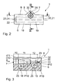
- Fig. 2
- eine Seitenansicht des Adapters aus Pfeilrichtung II nach Fig. 1, und
- Fig. 3
- einen Schnitt des Adapters gemäß der Schnittlinie III-III nach Fig. 2.
- Der in den Zeichnungen dargestellte Kontaktverbindungs-Adapter 1 dient zur Herstellung eines zeitweisen elektrischen Kontaktes zwischen einerseits einem genormten IS-1 / IS-4 / DF-1-Anschlussstecker 2 einer in Fig. 1 angeschnitten dargestellten Herzelektrode 3 und andererseits zwei üblichen Laborsteckern 4, 5 - umgangssprachlich als "Bananenstecker" bezeichnet - , die über entsprechende Kabel elektrisch mit den Anschlussbuchsen eines nicht näher dargestellten Reizschwellenanalysators zu verbinden sind.
- Der Adapter 1 weist einen im Wesentlichen quaderförmigen Grundkörper 6 auf, der aus einem durchsichtigen, sterilisierbarem Kunststoffmaterial in einem Stück spritzgegossen ist. Im Grundkörper ist etwa mittig zur Oberseite hin gerückt eine dazu parallel verlaufende, buchsenartige Aufnahme 7 angelegt, die mit ihrem zur Außenseite hin weisenden Querschnittsbereich in einem im Profil dreieck-förmigen Vorsprung 8 untergebracht ist. Dieser erstreckt sich über die Oberseite 9 des Adapters 1 hinweg.
- Wie aus Fig. 1 deutlich wird, ist die Aufnahme 7 ausgehend von einem mündungsseitigen Steckbereich mit dem Durchmesser d10 zweifach abgestuft, nämlich auf einen etwas engeren Steckbereich 11 mit dem Durchmesser d11 und einem am tiefsten gelegenen Steckbereich 12 mit einem noch kleineren Durchmesser d12. Die Steckbereiche 10, 11 und 12 sind in ihren Durchmessern d10, d11 und d12 an die entsprechenden Außendurchmesser D13, D14, D15 des Steckerschaftes 13, des Ringkontaktes 14 und des an der Spitze des Steckers 2 gelegenen Spitzenkontaktes 15 angepasst. Der Schaft 13 ist dabei vom Ringkontakt 14 durch eine doppelte umlaufende Ringdichtung 16 abgetrennt. Desgleichen ist auf dem dem Ringkontakt 14 folgenden Schaftbereich vor der Abstufung zum Spitzenkontakt 15 ein weiteres Paar von Ringdichtungen 17 vorgesehen.
- Zur Aufnahme der beiden Laborstecker 4, 5 weist der Adapter in zwei in Einsteckrichtung E hintereinander liegenden, dazu senkrechten Ebenen P18 und P19 je eine im Wesentlichen zylindrische Aufnahme 18, 19 auf. Wie aus Fig. 1 erkennbar ist, entsprechen diese Aufnahmen 18, 19 in der Tiefe etwa der Länge I der Laborstecker 4, 5 und enden kurz vor der der Mündung 20, 21 abgewandten Schmalseite 22 des Adapters 1. Dort sind sie über eine Öffnung 23, 24 jeweils für Sterilisationsflüssigkeit durchlässig.
- Wie insbesondere aus Fig. 3 deutlich wird, schneiden sich die Querschnitte der Aufnahme 7 für den IS-1 / IS-4 / DF-1-Stecker 2 einerseits und der beiden Aufnahmen 18, 19 für die Laborstecker 4, 5 andererseits knapp peripher, sodass die beiden Querschnittsvolumina über Kontaktfenster 25, 26 (Fig. 1) ineinander übergehen. Werden nun in die Aufnahme 7 der IS-1-Stecker 2 und in die Aufnahmen 18, 19 jeweils ein Laborstecker 4, 5 eingesteckt, so geben die Federlamellen 27 der Laborstecker 4, 5 über die Kontaktfenster 25, 26 jeweils eine optimale elektrische Verbindung zu dem Ringkontakt 14 bzw. Spitzenkontakt 15 des Steckers 2.
- Wie besonders aus Fig. 3 deutlich wird, weisen die beiden Aufnahmen 18, 19 zur Anpassung an die stufenförmige Durchmesserverringerung der Aufnahme 7 einen Versatz V zueinander auf.
- Für den oben erwähnten, in der Elektrode sitzenden Mandrin, der in Fig. 1 lediglich ausschnittsweise beim Bezugszeichen 28 angedeutet ist, ist die Aufnahme 7 für den Stecker 2 über ihre komplette Länge seitlich durch einen im Vorsprung 8 angelegten Durchführungsschlitz 29 offen. Ferner setzt sich deren innerster Steckbereich 12 in ein Durchführungsloch 30 in koaxialer Richtung fort, das sich zu einer trichterförmigen Mündung 31 weitet. Über den Durchführungsschlitz 29 und das Durchführungsloch 30 ist der vor dem Spitzenkontakt 15 laufenden Abschnitt des Mandrins 28 in die Aufnahme 7 von der Seite her einführbar. Ein direktes Einfädeln ist nicht möglich, da der Mandrin in einem voluminösen Steuergriff endet. Nach dem Einführen des Mandrins in die Aufnahme 7 kann der Stecker 2 dann eingesteckt werden. Zur Erleichterung der Mandrin-Einführung ist der Durchführungsschlitz 29 mit Einführschrägen 32 versehen.
Claims (8)
- Kontaktverbindungs-Adapter zur Herstellung eines zeitweisen elektrischen Kontaktes zwischen einem ersten Stecker (2), insbesondere einem Norm-Anschluss-Stecker einer Herzschrittmacher-Elekrode (3), und mindestens einem weiteren Stecker (4, 5), insbesondere einem üblichen Laborstecker eines Laborkabels zur zeitweisen Verbindung der Elektrode (3) mit einem Reizschwellenanalysator, gekennzeichnet durch- einen Grundkörper (6),- eine erste im Grundkörper (6) angelegte, buchsenartige Aufnahme (7) für den einen Stecker (2), und- mindestens eine zweite im Grundkörper (6) angelegte, buchsenartige Aufnahme (18, 19) für den mindestens einen weiteren Stecker (4, 5), wobei sich die Querschnitte der ersten und der mindestens einen zweiten Aufnahme (7, 18, 19) derart peripher schneiden, dass in die Aufnahmen (7, 18, 19) eingesteckte Stecker (2, 4, 5) an ihren seitlichen Kontaktflächen (14, 15, 27) aneinander anliegen und einen elektrischen Kontakt herstellen.
- Kontaktverbindungs-Adapter nach Anspruch 1, dadurch gekennzeichnet, dass die Aufnahmen (7, 18, 19) für die Stecker (2, 4, 5) mit ihren Längsachsen in einander senkrecht schneidenden Ebenen (P7, P18, P19) angeordnet sind.
- Kontaktverbindungs-Adapter nach Anspruch 1 oder 2, dadurch gekennzeichnet, dass für einen bipolaren oder unipolaren Stecker (2) eine mit zunehmender Buchsentiefe zweifach im Durchmesser (d11, d12) abgestufte Aufnahme (7) zur deren Anpassung an die stufig abnehmenden Durchmesser (D13, D14, D15) von Steckerschaft (13), Ringkontakt (14) und Spitzenkontakt (15) des Steckers (2) vorgesehen ist.
- Kontaktverbindungs-Adapter nach Anspruch 3, dadurch gekennzeichnet, dass zwei parallel nebeneinander liegende Aufnahmen (18, 19) für zwei weitere Stecker (4, 5) im Grundkörper (6) angelegt sind, die einen Versatz (V) zueinander entsprechend der Durchmesserverringerung zwischen Ring- (14) und Spitzenkontakt (15) des bipolaren Steckers (2) aufweisen.
- Kontaktverbindungs-Adapter nach einem der vorgenannten Ansprüche, dadurch gekennzeichnet, dass das die Aufnahme (7) für den ersten Stecker (2) sowohl am tiefen Ende in längsachsialer Richtung über eine dünne Durchführung (30) als auch entlang ihrer gesamten Tiefe über einen seitlichen, längsparallelen Durchführungsschlitz (29) offen ist.
- Kontaktverbindungs-Adapter nach Anspruch 5, dadurch gekennzeichnet, dass der Durchführungsschlitz (29) mit Einführschrägen (32) versehen ist.
- Kontaktverbindungs-Adapter nach einem der vorgenannten Ansprüche, dadurch gekennzeichnet, dass die mindestens eine Aufnahme (18, 19) für den mindestens einen weiteren Stecker (4, 5) am tiefen Ende ein Öffnung (23, 24) aufweist.
- Kontaktverbindungs-Adapter nach einem der vorgenannten Ansprüche, dadurch gekennzeichnet, dass der Grundkörper (6) aus einem durchsichtigen, sterilisierbaren Kunststoffmaterial besteht.
Applications Claiming Priority (1)
| Application Number | Priority Date | Filing Date | Title |
|---|---|---|---|
| DE102005018806A DE102005018806A1 (de) | 2005-04-22 | 2005-04-22 | Kontaktverbindungs-Adapter zur Herstellung eines zeitweisen elektrischen Kontaktes zwischen zwei Steckern |
Publications (2)
| Publication Number | Publication Date |
|---|---|
| EP1714672A1 true EP1714672A1 (de) | 2006-10-25 |
| EP1714672B1 EP1714672B1 (de) | 2007-10-31 |
Family
ID=36779551
Family Applications (1)
| Application Number | Title | Priority Date | Filing Date |
|---|---|---|---|
| EP06006091A Expired - Lifetime EP1714672B1 (de) | 2005-04-22 | 2006-03-24 | Kontaktverbindungs-Adapter zur Herstellung eines zeitweisen elektrischen Kontaktes zwischen zwei Steckern |
Country Status (4)
| Country | Link |
|---|---|
| US (1) | US7217163B2 (de) |
| EP (1) | EP1714672B1 (de) |
| AT (1) | ATE376858T1 (de) |
| DE (2) | DE102005018806A1 (de) |
Cited By (1)
| Publication number | Priority date | Publication date | Assignee | Title |
|---|---|---|---|---|
| WO2012102745A3 (en) * | 2011-01-27 | 2012-11-01 | Medtronic, Inc. | Interface adapters for implantable medical electrical leads |
Families Citing this family (7)
| Publication number | Priority date | Publication date | Assignee | Title |
|---|---|---|---|---|
| WO2008118430A1 (en) * | 2007-03-26 | 2008-10-02 | Gkn Aerospace Services Structures Corp. | Connector usable with multiple layered connections and method of use thereof |
| US7677929B2 (en) * | 2008-06-04 | 2010-03-16 | Daphne Bradford-Stagg | Sacrificial laptop computer power connector |
| US7854633B2 (en) * | 2008-09-05 | 2010-12-21 | Apple Inc. | Low profile plug receptacle |
| US8353729B2 (en) * | 2010-02-18 | 2013-01-15 | Apple Inc. | Low profile connector system |
| JP2014219436A (ja) * | 2013-04-30 | 2014-11-20 | 株式会社リコー | 読み出し装置及び同装置を供える画像形成装置 |
| RU193619U1 (ru) * | 2017-09-11 | 2019-11-07 | Александр Николаевич Александров | Переходник к постоянному кардиостимулятору для временной электрокардиостимуляции |
| WO2019050438A1 (ru) * | 2017-09-11 | 2019-03-14 | Александр Николаевич АЛЕКСАНДРОВ | Переходник к деимплантированному кардиостимулятору для временной электрокардиостимуляции |
Citations (4)
| Publication number | Priority date | Publication date | Assignee | Title |
|---|---|---|---|---|
| US5782892A (en) * | 1997-04-25 | 1998-07-21 | Medtronic, Inc. | Medical lead adaptor for external medical device |
| DE19810262A1 (de) | 1998-03-10 | 1999-09-16 | Bisping Hans Juergen | Testkabelanordnung |
| US6343233B1 (en) * | 1997-04-25 | 2002-01-29 | Medtronic, Inc. | Medical lead adaptor |
| US20030120327A1 (en) * | 2001-12-20 | 2003-06-26 | Mark Tobritzhofer | Medical lead adaptor assembly with retainer |
Family Cites Families (7)
| Publication number | Priority date | Publication date | Assignee | Title |
|---|---|---|---|---|
| US4860750A (en) * | 1986-04-17 | 1989-08-29 | Intermedics Inc. | Sidelock pacer lead connector |
| DE8808698U1 (de) * | 1988-07-04 | 1988-09-22 | Biotronik Meß- und Therapiegeräte GmbH & Co Ingenieurbüro Berlin, 1000 Berlin | Schutzelement für einen koaxialen Herzschrittmacherstecker |
| US5413595A (en) * | 1993-10-15 | 1995-05-09 | Pacesetter, Inc. | Lead retention and seal for implantable medical device |
| EP0826390A3 (de) * | 1996-08-06 | 1998-03-25 | Sulzer Osypka GmbH | Verbindungselement für ein äusseres Endstück einer chirurgischen Elektrode |
| DE19938960A1 (de) * | 1998-03-10 | 2001-02-22 | Bisping Hans Juergen | Testkabelanordnung |
| US6044302A (en) * | 1999-01-07 | 2000-03-28 | Cardiac Pacemakers, Inc. | Apparatus for connecting a left ventricular access lead to a cardiac rhythm management device |
| US7047077B2 (en) * | 2002-08-16 | 2006-05-16 | Cardiac Pacemakers, Inc. | Connector port construction technique for implantable medical device |
-
2005
- 2005-04-22 DE DE102005018806A patent/DE102005018806A1/de not_active Withdrawn
-
2006
- 2006-03-24 DE DE502006000157T patent/DE502006000157D1/de not_active Expired - Lifetime
- 2006-03-24 EP EP06006091A patent/EP1714672B1/de not_active Expired - Lifetime
- 2006-03-24 AT AT06006091T patent/ATE376858T1/de not_active IP Right Cessation
- 2006-04-24 US US11/409,266 patent/US7217163B2/en not_active Expired - Fee Related
Patent Citations (5)
| Publication number | Priority date | Publication date | Assignee | Title |
|---|---|---|---|---|
| US5782892A (en) * | 1997-04-25 | 1998-07-21 | Medtronic, Inc. | Medical lead adaptor for external medical device |
| US6343233B1 (en) * | 1997-04-25 | 2002-01-29 | Medtronic, Inc. | Medical lead adaptor |
| DE19810262A1 (de) | 1998-03-10 | 1999-09-16 | Bisping Hans Juergen | Testkabelanordnung |
| US6708067B1 (en) | 1998-03-10 | 2004-03-16 | Hans Jurgen Bisping | Test cable arrangement |
| US20030120327A1 (en) * | 2001-12-20 | 2003-06-26 | Mark Tobritzhofer | Medical lead adaptor assembly with retainer |
Non-Patent Citations (1)
| Title |
|---|
| ANONYMOUS: "Cable connector for electrical measurements", RESEARCH DISCLOSURE, MASON PUBLICATIONS, HAMPSHIRE, GB, vol. 395, no. 11, March 1997 (1997-03-01), XP007121588, ISSN: 0374-4353 * |
Cited By (1)
| Publication number | Priority date | Publication date | Assignee | Title |
|---|---|---|---|---|
| WO2012102745A3 (en) * | 2011-01-27 | 2012-11-01 | Medtronic, Inc. | Interface adapters for implantable medical electrical leads |
Also Published As
| Publication number | Publication date |
|---|---|
| US20060240714A1 (en) | 2006-10-26 |
| DE502006000157D1 (de) | 2007-12-13 |
| ATE376858T1 (de) | 2007-11-15 |
| EP1714672B1 (de) | 2007-10-31 |
| DE102005018806A1 (de) | 2006-10-26 |
| US7217163B2 (en) | 2007-05-15 |
Similar Documents
| Publication | Publication Date | Title |
|---|---|---|
| DE60113472T2 (de) | Elektrischer Steckverbinder für eine mehrpolige medizinische Elektrode | |
| DE69011753T2 (de) | Transkutane Verbindungseinrichtung. | |
| DE2853809C2 (de) | ||
| DE4402058C1 (de) | Implantierbares, passageres Elektrodenkabel | |
| EP1253964B1 (de) | Spannadapter für einen katheter | |
| DE2309204C2 (de) | Steckvorrichtung für den Anschluß einer Anzahl von Zuleitungen für Herzelektroden an einen Herzschrittmacher | |
| DE4116520A1 (de) | Implantierbarer leitfaehiger verbinder | |
| DE69309764T2 (de) | Impulsgenerator mit Verbindungsöffnungen für Diagnose | |
| EP1714672B1 (de) | Kontaktverbindungs-Adapter zur Herstellung eines zeitweisen elektrischen Kontaktes zwischen zwei Steckern | |
| EP2166940B1 (de) | Elektrodenanordnung und messvorrichtung zur messung der elektrischen aktivität in einem elektrisch aktiven gewebe | |
| DE19938960A1 (de) | Testkabelanordnung | |
| EP1061995B1 (de) | Testkabelanordnung | |
| EP3630266A1 (de) | Elektromedizinischer adapter, elektromedizinische elektrode und elektromedizinischer impulsgeber | |
| DE102012009058B4 (de) | Bipolarer Elektrodenanschluss | |
| DE102011013170B4 (de) | Temporärer berührungssicherer Verbinder für Herzdrähte | |
| DE102013001021B4 (de) | Externer Herzschrittmacher mit einer über einen Steckverbinder angeschlossenen, temporär mit einem Herzen verbindbaren Elektrode | |
| EP0823263A1 (de) | Verbindungselement für ein äusseres Endstück einer chirurgischen Elektrode | |
| DE102008007542A1 (de) | Multipolare Elektrodenleitung | |
| EP3416577A1 (de) | Chirurgiegeräte-mehrfachbuchse, elektrochirurgie-hochfrequenzgenerator, elektrochirurgiegerätestecker und elektrochirurgisches system | |
| DE69725341T2 (de) | Kontaktelemente einer vielpoligen steckverbindung an einem elektrodenkabel für eine implantierbare medizinische vorrichtung | |
| DE102011109880B4 (de) | Verlängerungskabel für temporäre Herzschrittmacher Elektroden | |
| DE102008043452A1 (de) | Vorrichtung zum Einbringen von medizinischen Implantaten | |
| WO2022189612A1 (de) | Anschlussstecker für eine elektromedizinische elektrode, einen gegenstecker, elektromedizinischer impulsgeber, elektromedizinische elektrode und elektromedizinische steckverbindung | |
| DE202012003220U1 (de) | Nadelelektrode mit Griffteil mit flächig ausgeformter Oberfläche | |
| WO2022002543A1 (de) | Medizinisches handhabungsset |
Legal Events
| Date | Code | Title | Description |
|---|---|---|---|
| PUAI | Public reference made under article 153(3) epc to a published international application that has entered the european phase |
Free format text: ORIGINAL CODE: 0009012 |
|
| AK | Designated contracting states |
Kind code of ref document: A1 Designated state(s): AT BE BG CH CY CZ DE DK EE ES FI FR GB GR HU IE IS IT LI LT LU LV MC NL PL PT RO SE SI SK TR |
|
| AX | Request for extension of the european patent |
Extension state: AL BA HR MK YU |
|
| 17P | Request for examination filed |
Effective date: 20061027 |
|
| GRAP | Despatch of communication of intention to grant a patent |
Free format text: ORIGINAL CODE: EPIDOSNIGR1 |
|
| GRAC | Information related to communication of intention to grant a patent modified |
Free format text: ORIGINAL CODE: EPIDOSCIGR1 |
|
| AKX | Designation fees paid |
Designated state(s): AT BE BG CH CY CZ DE DK EE ES FI FR GB GR HU IE IS IT LI LT LU LV MC NL PL PT RO SE SI SK TR |
|
| GRAS | Grant fee paid |
Free format text: ORIGINAL CODE: EPIDOSNIGR3 |
|
| GRAA | (expected) grant |
Free format text: ORIGINAL CODE: 0009210 |
|
| AK | Designated contracting states |
Kind code of ref document: B1 Designated state(s): AT BE BG CH CY CZ DE DK EE ES FI FR GB GR HU IE IS IT LI LT LU LV MC NL PL PT RO SE SI SK TR |
|
| REG | Reference to a national code |
Ref country code: GB Ref legal event code: FG4D Free format text: NOT ENGLISH |
|
| REG | Reference to a national code |
Ref country code: SE Ref legal event code: TRGR |
|
| REG | Reference to a national code |
Ref country code: IE Ref legal event code: FG4D Free format text: LANGUAGE OF EP DOCUMENT: GERMAN |
|
| REG | Reference to a national code |
Ref country code: CH Ref legal event code: EP |
|
| REF | Corresponds to: |
Ref document number: 502006000157 Country of ref document: DE Date of ref document: 20071213 Kind code of ref document: P |
|
| GBT | Gb: translation of ep patent filed (gb section 77(6)(a)/1977) |
Effective date: 20071127 |
|
| ET | Fr: translation filed | ||
| PG25 | Lapsed in a contracting state [announced via postgrant information from national office to epo] |
Ref country code: ES Free format text: LAPSE BECAUSE OF FAILURE TO SUBMIT A TRANSLATION OF THE DESCRIPTION OR TO PAY THE FEE WITHIN THE PRESCRIBED TIME-LIMIT Effective date: 20080211 |
|
| PG25 | Lapsed in a contracting state [announced via postgrant information from national office to epo] |
Ref country code: SI Free format text: LAPSE BECAUSE OF FAILURE TO SUBMIT A TRANSLATION OF THE DESCRIPTION OR TO PAY THE FEE WITHIN THE PRESCRIBED TIME-LIMIT Effective date: 20071031 Ref country code: PT Free format text: LAPSE BECAUSE OF FAILURE TO SUBMIT A TRANSLATION OF THE DESCRIPTION OR TO PAY THE FEE WITHIN THE PRESCRIBED TIME-LIMIT Effective date: 20080331 Ref country code: PL Free format text: LAPSE BECAUSE OF FAILURE TO SUBMIT A TRANSLATION OF THE DESCRIPTION OR TO PAY THE FEE WITHIN THE PRESCRIBED TIME-LIMIT Effective date: 20071031 Ref country code: LV Free format text: LAPSE BECAUSE OF FAILURE TO SUBMIT A TRANSLATION OF THE DESCRIPTION OR TO PAY THE FEE WITHIN THE PRESCRIBED TIME-LIMIT Effective date: 20071031 Ref country code: LT Free format text: LAPSE BECAUSE OF FAILURE TO SUBMIT A TRANSLATION OF THE DESCRIPTION OR TO PAY THE FEE WITHIN THE PRESCRIBED TIME-LIMIT Effective date: 20071031 Ref country code: IS Free format text: LAPSE BECAUSE OF FAILURE TO SUBMIT A TRANSLATION OF THE DESCRIPTION OR TO PAY THE FEE WITHIN THE PRESCRIBED TIME-LIMIT Effective date: 20080229 Ref country code: BG Free format text: LAPSE BECAUSE OF FAILURE TO SUBMIT A TRANSLATION OF THE DESCRIPTION OR TO PAY THE FEE WITHIN THE PRESCRIBED TIME-LIMIT Effective date: 20080131 |
|
| REG | Reference to a national code |
Ref country code: IE Ref legal event code: FD4D |
|
| PG25 | Lapsed in a contracting state [announced via postgrant information from national office to epo] |
Ref country code: DK Free format text: LAPSE BECAUSE OF FAILURE TO SUBMIT A TRANSLATION OF THE DESCRIPTION OR TO PAY THE FEE WITHIN THE PRESCRIBED TIME-LIMIT Effective date: 20071031 Ref country code: CZ Free format text: LAPSE BECAUSE OF FAILURE TO SUBMIT A TRANSLATION OF THE DESCRIPTION OR TO PAY THE FEE WITHIN THE PRESCRIBED TIME-LIMIT Effective date: 20071031 |
|
| PG25 | Lapsed in a contracting state [announced via postgrant information from national office to epo] |
Ref country code: RO Free format text: LAPSE BECAUSE OF FAILURE TO SUBMIT A TRANSLATION OF THE DESCRIPTION OR TO PAY THE FEE WITHIN THE PRESCRIBED TIME-LIMIT Effective date: 20071031 Ref country code: SK Free format text: LAPSE BECAUSE OF FAILURE TO SUBMIT A TRANSLATION OF THE DESCRIPTION OR TO PAY THE FEE WITHIN THE PRESCRIBED TIME-LIMIT Effective date: 20071031 |
|
| PLBE | No opposition filed within time limit |
Free format text: ORIGINAL CODE: 0009261 |
|
| STAA | Information on the status of an ep patent application or granted ep patent |
Free format text: STATUS: NO OPPOSITION FILED WITHIN TIME LIMIT |
|
| BERE | Be: lapsed |
Owner name: BIOTRONIK CRM PATENT A.G. Effective date: 20080331 |
|
| 26N | No opposition filed |
Effective date: 20080801 |
|
| PG25 | Lapsed in a contracting state [announced via postgrant information from national office to epo] |
Ref country code: MC Free format text: LAPSE BECAUSE OF NON-PAYMENT OF DUE FEES Effective date: 20080331 Ref country code: IE Free format text: LAPSE BECAUSE OF FAILURE TO SUBMIT A TRANSLATION OF THE DESCRIPTION OR TO PAY THE FEE WITHIN THE PRESCRIBED TIME-LIMIT Effective date: 20071031 |
|
| PG25 | Lapsed in a contracting state [announced via postgrant information from national office to epo] |
Ref country code: EE Free format text: LAPSE BECAUSE OF FAILURE TO SUBMIT A TRANSLATION OF THE DESCRIPTION OR TO PAY THE FEE WITHIN THE PRESCRIBED TIME-LIMIT Effective date: 20071031 Ref country code: GR Free format text: LAPSE BECAUSE OF FAILURE TO SUBMIT A TRANSLATION OF THE DESCRIPTION OR TO PAY THE FEE WITHIN THE PRESCRIBED TIME-LIMIT Effective date: 20080201 |
|
| PG25 | Lapsed in a contracting state [announced via postgrant information from national office to epo] |
Ref country code: FI Free format text: LAPSE BECAUSE OF FAILURE TO SUBMIT A TRANSLATION OF THE DESCRIPTION OR TO PAY THE FEE WITHIN THE PRESCRIBED TIME-LIMIT Effective date: 20071031 Ref country code: BE Free format text: LAPSE BECAUSE OF NON-PAYMENT OF DUE FEES Effective date: 20080331 |
|
| PGFP | Annual fee paid to national office [announced via postgrant information from national office to epo] |
Ref country code: NL Payment date: 20090324 Year of fee payment: 4 |
|
| PG25 | Lapsed in a contracting state [announced via postgrant information from national office to epo] |
Ref country code: CY Free format text: LAPSE BECAUSE OF FAILURE TO SUBMIT A TRANSLATION OF THE DESCRIPTION OR TO PAY THE FEE WITHIN THE PRESCRIBED TIME-LIMIT Effective date: 20071031 |
|
| PG25 | Lapsed in a contracting state [announced via postgrant information from national office to epo] |
Ref country code: AT Free format text: LAPSE BECAUSE OF NON-PAYMENT OF DUE FEES Effective date: 20080324 |
|
| PG25 | Lapsed in a contracting state [announced via postgrant information from national office to epo] |
Ref country code: HU Free format text: LAPSE BECAUSE OF FAILURE TO SUBMIT A TRANSLATION OF THE DESCRIPTION OR TO PAY THE FEE WITHIN THE PRESCRIBED TIME-LIMIT Effective date: 20080501 Ref country code: LU Free format text: LAPSE BECAUSE OF NON-PAYMENT OF DUE FEES Effective date: 20080324 |
|
| PG25 | Lapsed in a contracting state [announced via postgrant information from national office to epo] |
Ref country code: TR Free format text: LAPSE BECAUSE OF FAILURE TO SUBMIT A TRANSLATION OF THE DESCRIPTION OR TO PAY THE FEE WITHIN THE PRESCRIBED TIME-LIMIT Effective date: 20071031 |
|
| REG | Reference to a national code |
Ref country code: NL Ref legal event code: V1 Effective date: 20101001 |
|
| PG25 | Lapsed in a contracting state [announced via postgrant information from national office to epo] |
Ref country code: NL Free format text: LAPSE BECAUSE OF NON-PAYMENT OF DUE FEES Effective date: 20101001 |
|
| PGFP | Annual fee paid to national office [announced via postgrant information from national office to epo] |
Ref country code: IT Payment date: 20090331 Year of fee payment: 4 |
|
| PGFP | Annual fee paid to national office [announced via postgrant information from national office to epo] |
Ref country code: SE Payment date: 20120322 Year of fee payment: 7 Ref country code: GB Payment date: 20120322 Year of fee payment: 7 |
|
| REG | Reference to a national code |
Ref country code: SE Ref legal event code: EUG |
|
| PG25 | Lapsed in a contracting state [announced via postgrant information from national office to epo] |
Ref country code: SE Free format text: LAPSE BECAUSE OF NON-PAYMENT OF DUE FEES Effective date: 20130325 |
|
| GBPC | Gb: european patent ceased through non-payment of renewal fee |
Effective date: 20130324 |
|
| PG25 | Lapsed in a contracting state [announced via postgrant information from national office to epo] |
Ref country code: GB Free format text: LAPSE BECAUSE OF NON-PAYMENT OF DUE FEES Effective date: 20130324 |
|
| REG | Reference to a national code |
Ref country code: FR Ref legal event code: PLFP Year of fee payment: 10 |
|
| PGFP | Annual fee paid to national office [announced via postgrant information from national office to epo] |
Ref country code: FR Payment date: 20150319 Year of fee payment: 10 |
|
| REG | Reference to a national code |
Ref country code: DE Ref legal event code: R082 Ref document number: 502006000157 Country of ref document: DE Representative=s name: RANDOLL, SOEREN, DIPL.-CHEM. UNIV. DR. RER. NA, DE |
|
| REG | Reference to a national code |
Ref country code: FR Ref legal event code: ST Effective date: 20161130 |
|
| PG25 | Lapsed in a contracting state [announced via postgrant information from national office to epo] |
Ref country code: FR Free format text: LAPSE BECAUSE OF NON-PAYMENT OF DUE FEES Effective date: 20160331 |
|
| REG | Reference to a national code |
Ref country code: DE Ref legal event code: R082 Ref document number: 502006000157 Country of ref document: DE Ref country code: DE Ref legal event code: R081 Ref document number: 502006000157 Country of ref document: DE Owner name: BIOTRONIK SE & CO. KG, DE Free format text: FORMER OWNER: BIOTRONIK CRM PATENT AG, BAAR, CH |
|
| PGFP | Annual fee paid to national office [announced via postgrant information from national office to epo] |
Ref country code: CH Payment date: 20180326 Year of fee payment: 13 |
|
| PGFP | Annual fee paid to national office [announced via postgrant information from national office to epo] |
Ref country code: DE Payment date: 20180328 Year of fee payment: 13 |
|
| REG | Reference to a national code |
Ref country code: DE Ref legal event code: R119 Ref document number: 502006000157 Country of ref document: DE |
|
| REG | Reference to a national code |
Ref country code: CH Ref legal event code: PL |
|
| PG25 | Lapsed in a contracting state [announced via postgrant information from national office to epo] |
Ref country code: CH Free format text: LAPSE BECAUSE OF NON-PAYMENT OF DUE FEES Effective date: 20190331 Ref country code: LI Free format text: LAPSE BECAUSE OF NON-PAYMENT OF DUE FEES Effective date: 20190331 Ref country code: DE Free format text: LAPSE BECAUSE OF NON-PAYMENT OF DUE FEES Effective date: 20191001 |