EP1714701A1 - Schredder mit Verdichtungsplatten - Google Patents
Schredder mit Verdichtungsplatten Download PDFInfo
- Publication number
- EP1714701A1 EP1714701A1 EP06007057A EP06007057A EP1714701A1 EP 1714701 A1 EP1714701 A1 EP 1714701A1 EP 06007057 A EP06007057 A EP 06007057A EP 06007057 A EP06007057 A EP 06007057A EP 1714701 A1 EP1714701 A1 EP 1714701A1
- Authority
- EP
- European Patent Office
- Prior art keywords
- shredder
- compression
- plates
- output aperture
- shredded material
- Prior art date
- Legal status (The legal status is an assumption and is not a legal conclusion. Google has not performed a legal analysis and makes no representation as to the accuracy of the status listed.)
- Withdrawn
Links
- 230000006835 compression Effects 0.000 claims abstract description 83
- 238000007906 compression Methods 0.000 claims abstract description 83
- 239000000463 material Substances 0.000 claims abstract description 41
- 239000000853 adhesive Substances 0.000 description 2
- 230000001070 adhesive effect Effects 0.000 description 2
- 238000000034 method Methods 0.000 description 2
- 238000004026 adhesive bonding Methods 0.000 description 1
- 230000007423 decrease Effects 0.000 description 1
- 230000000694 effects Effects 0.000 description 1
- 230000005484 gravity Effects 0.000 description 1
Images

Classifications
-
- B—PERFORMING OPERATIONS; TRANSPORTING
- B30—PRESSES
- B30B—PRESSES IN GENERAL
- B30B9/00—Presses specially adapted for particular purposes
- B30B9/30—Presses specially adapted for particular purposes for baling; Compression boxes therefor
- B30B9/3003—Details
- B30B9/3035—Means for conditioning the material to be pressed, e.g. paper shredding means
-
- B—PERFORMING OPERATIONS; TRANSPORTING
- B02—CRUSHING, PULVERISING, OR DISINTEGRATING; PREPARATORY TREATMENT OF GRAIN FOR MILLING
- B02C—CRUSHING, PULVERISING, OR DISINTEGRATING IN GENERAL; MILLING GRAIN
- B02C18/00—Disintegrating by knives or other cutting or tearing members which chop material into fragments
- B02C18/0007—Disintegrating by knives or other cutting or tearing members which chop material into fragments specially adapted for disintegrating documents
-
- B—PERFORMING OPERATIONS; TRANSPORTING
- B02—CRUSHING, PULVERISING, OR DISINTEGRATING; PREPARATORY TREATMENT OF GRAIN FOR MILLING
- B02C—CRUSHING, PULVERISING, OR DISINTEGRATING IN GENERAL; MILLING GRAIN
- B02C18/00—Disintegrating by knives or other cutting or tearing members which chop material into fragments
- B02C18/06—Disintegrating by knives or other cutting or tearing members which chop material into fragments with rotating knives
- B02C18/16—Details
- B02C18/22—Feed or discharge means
- B02C18/2225—Feed means
-
- B—PERFORMING OPERATIONS; TRANSPORTING
- B30—PRESSES
- B30B—PRESSES IN GENERAL
- B30B9/00—Presses specially adapted for particular purposes
- B30B9/30—Presses specially adapted for particular purposes for baling; Compression boxes therefor
- B30B9/3082—Presses specially adapted for particular purposes for baling; Compression boxes therefor with compression means other than rams performing a rectilinear movement
-
- B—PERFORMING OPERATIONS; TRANSPORTING
- B02—CRUSHING, PULVERISING, OR DISINTEGRATING; PREPARATORY TREATMENT OF GRAIN FOR MILLING
- B02C—CRUSHING, PULVERISING, OR DISINTEGRATING IN GENERAL; MILLING GRAIN
- B02C18/00—Disintegrating by knives or other cutting or tearing members which chop material into fragments
- B02C18/0007—Disintegrating by knives or other cutting or tearing members which chop material into fragments specially adapted for disintegrating documents
- B02C2018/0061—Disintegrating by knives or other cutting or tearing members which chop material into fragments specially adapted for disintegrating documents with compacting devices for the disintegrated material
Definitions
- the invention relates to the compression of shredded material output from a shredder.
- Conventional shredding devices output strips of shredded material, e.g. paper.
- the strips of shredded material are substantially uncompressed, and can quickly fill a receptacle used to collect them. It is desirable to compress the shredded material in some way, to extend the usage of the receptacle.
- a compression device adapted for use with a shredder having an output aperture from which shredded material is output, comprising first and second compression plates, each compression plate adapted for attachment at the output aperture of the shredder, and each being pivotably moveable between respective first positions in which the compression plates act to impede the flow of the shredded material away from the output aperture of the shredder, to respective second positions in which the shredded material is allowed to flow away from the output aperture of the shredder, between the compression plates, wherein the free ends of the compression plates, remote from their attachment at the output aperture of the shredder, are biased towards each other by respective resilient members.
- the compression device in accordance with the invention therefore causes at least some of the strips of material to concertina.
- Each compression plate may be hingeably attachable to the shredder at the output aperture thereof.
- Each compression plate may be hingeably attachable to the shredder by means of hinges, or fasteners or gluing.
- Each resilient member may be an elastic band which, preferably, extends over a portion of the compression plate and is connectable at each of its ends to the shredder.
- each resilient member may be provided as an integral part of the hinge of each compressor plate, where the plates are hingeably attachable to the shredder, for example as part of a living hinge.
- the compression plates may be elongate in shape, to impede the flow of shredded material away from an elongate output aperture of the shredder.
- Each elongate compression plate may have a first elongate edge and a second elongate edge joined to the first elongate edge by first and second end edges of the compression plate.
- the first and second elongate edges may each have a length which is substantially equal to or greater than the length of elongate edges of the output aperture of the shredder.
- the first elongate edge of the first compression plate may be attachable to the shredder alongside a first elongate edge of the output aperture
- the first elongate edge of the second compression plate may be attachable to the shredder alongside a second elongate edge of the output aperture
- the compression device may be provided with one or more pressure sensing and actuating elements, to measure the pressure on the compression plates, and to cause the compression plates to move abruptly from the first position to the second position when the pressure on the plates equals or substantially equals a predetermined level.
- the compression device may be provided with one or more pressure sensing and actuating elements, to measure the pressure on the compression plates, and to cause the compression plates to move abruptly from the second position to the first position when the pressure on the plates drops below a predetermined level.
- the actuating elements may thus be configured to effect pivotal movement of the compression plates. Actuating elements for providing such movement are well, for example a electric motor with appropriate gearing could be used.
- a shredding device including a shredder and a compression device according to the first aspect of the invention.
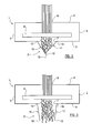
- FIGS 1, 2 and 3 show a shredder 1 and a compression device 2.
- the shredder comprises a casing which is generally box-shaped, and comprises four sides 3 (only two of which are visible in each of the Figures), which join a first face 4, and a second face 5.
- the first face 4 is provided with an elongate input aperture 6, through which material, such as paper, which is to be shredded is fed into the shredder.
- the second face 5 is provided with an elongate output aperture 7, from which shredded material is output from the shredder.
- the shredder casing contains a shredding head 8, which receives material from the input aperture 6, shreds it, and outputs the shredded material to the output aperture 7.
- the shredding head 8 may shred the material into elongate strips.
- the shredder may be designed to fit onto a receptacle for the shredded material, i.e. may comprise a so-called 'bin-top' shredder.
- the shredder may be positioned over a receptacle for the shredded material.
- Such shredders are often referred to as 'cabinet' shredders.
- the first face 4 of the shredder comprises an upper, generally horizontal surface of the shredder
- the second face 5 comprises a lower, generally horizontal surface of the shredder.
- Material may be easily fed into the shredder through the elongate input aperture 6 in the upper face 4, and shredded material may easily fall away from the elongate output aperture 7 in the lower face 5 under the influence of gravity, into the receptacle beneath the shredder.
- the compression device 2 comprises a first compression plate 10 and a second compression plate 11.
- Each compression plate is elongate in shape, and comprises a first elongate edge 12 and a second elongate edge 13 joined to the first elongate edge 12 by first and second end edges 14, 15.
- the first and second elongate edges 12, 13 each have a length which is substantially equal to or greater than the length of elongate edges of the elongate output aperture 7 of the shredder.
- the first elongate edge 12 is attached to the face 5 of the shredder alongside opposite elongate edges of the output aperture 7, as shown.
- the attachment may be by any suitable fastening means, such as a strip of adhesive fastener 16, which, for each compression plate, is adhered to the edge 12 of each plate and the face 5 of the shredder, to attach the plate to the shredder.
- Each compression plate 10, 11 is hingeably attached to the shredder by the adhesive fastener, such that the plate is movable from a first position (shown in Figure 2) in which it acts to impede the flow of shredded material away from the output aperture 7 of the shredder, to a second position (shown in Figure 3) in which the shredded material is allowed to flow away from the output aperture 7 of the shredder, and from the second position to the first position.
- each compression plate 10, 11 When in the first position, the compression plates 10, 11 overlap at their second elongate edges 13, and form a substantially V-shaped compartment adjacent the output aperture 7 of the shredder.
- Each compression plate 10, 11 is tensioned by a resilient member 17, comprising an elastic band, which is fixed to the shredder over a portion of the compression plate, as shown.
- Each resilient member acts to bias the plate over which it is fixed into the first position, and controls movement of the plate from the first position to the second position and vice versa.
- the compression plates of the compression device are attached to the shredder, as described above, and the shredder/compression device combination placed over a receptacle for use.
- the compression plates 10, 11 are each biased by the resilient members 17 into their first position, shown in Figure 2.
- Material to be shredded is fed through the input aperture 6 of the shredder and is shredded by the shredding head 8 into strips of shredded material.
- the strips of shredded material are output from the shredding head in a relatively uncompressed form, and are output from the shredder through the output aperture 7.
- each plate will move towards its first position.
- the compression plates reach their second position, the compressed strips of shredded material are allowed to flow away from the output aperture 7 into a receptacle (not shown) for their collection. Compression of the strips of shredded material prior to collection thereof in the receptacle, allows more shredded material to be collected before the receptacle requires emptying.
Landscapes
- Engineering & Computer Science (AREA)
- Food Science & Technology (AREA)
- Mechanical Engineering (AREA)
- Crushing And Pulverization Processes (AREA)
Applications Claiming Priority (1)
| Application Number | Priority Date | Filing Date | Title |
|---|---|---|---|
| GB0508149A GB2425272B (en) | 2005-04-22 | 2005-04-22 | Improvements relating to shredders |
Publications (1)
| Publication Number | Publication Date |
|---|---|
| EP1714701A1 true EP1714701A1 (de) | 2006-10-25 |
Family
ID=34639947
Family Applications (1)
| Application Number | Title | Priority Date | Filing Date |
|---|---|---|---|
| EP06007057A Withdrawn EP1714701A1 (de) | 2005-04-22 | 2006-04-03 | Schredder mit Verdichtungsplatten |
Country Status (3)
| Country | Link |
|---|---|
| US (1) | US20070023552A1 (de) |
| EP (1) | EP1714701A1 (de) |
| GB (1) | GB2425272B (de) |
Cited By (3)
| Publication number | Priority date | Publication date | Assignee | Title |
|---|---|---|---|---|
| NL2006618C2 (nl) * | 2011-04-18 | 2012-10-22 | Keywaste B V | Persinrichting. |
| GB2613589A (en) * | 2021-12-07 | 2023-06-14 | Brightthing Brands Ltd | Combined shredding and compressing system |
| CN119076157A (zh) * | 2017-09-26 | 2024-12-06 | 广东精锐精密工业有限公司 | 快速进纸的碎纸机 |
Families Citing this family (3)
| Publication number | Priority date | Publication date | Assignee | Title |
|---|---|---|---|---|
| US7537176B2 (en) * | 2007-05-11 | 2009-05-26 | Jinlong Shen | Shredder with shreds containment and safety mechanisms |
| US9027862B2 (en) * | 2011-04-21 | 2015-05-12 | Enable International Limited | Shredder that produces crinkle paper stripes |
| US20140263782A1 (en) * | 2013-03-13 | 2014-09-18 | ACCO Brands Corporation | Paper shredder with output deflector |
Citations (3)
| Publication number | Priority date | Publication date | Assignee | Title |
|---|---|---|---|---|
| GB1313094A (en) * | 1969-04-04 | 1973-04-11 | Ross T S | Receptacle for waste material |
| US5637099A (en) * | 1994-06-09 | 1997-06-10 | Durdin; Daniel J. | Needle handling apparatus and methods |
| JP2001300339A (ja) * | 2000-04-18 | 2001-10-30 | Taisei Denki Kogyo Kk | シュレッダー付ごみ圧縮装置 |
Family Cites Families (10)
| Publication number | Priority date | Publication date | Assignee | Title |
|---|---|---|---|---|
| US3754498A (en) * | 1971-12-17 | 1973-08-28 | R Gil | Apparatus for shredding and baling paper |
| DE2720341A1 (de) * | 1977-05-06 | 1978-11-09 | Edgard Jacques Maillet | Vorrichtung zum zerkleinern |
| US4410315A (en) * | 1980-10-03 | 1983-10-18 | Beloit Corporation | Low velocity trim removal means and method |
| US4410086A (en) * | 1982-03-05 | 1983-10-18 | Simpson James L | Medical appliance disposal container |
| US4488643A (en) * | 1983-10-28 | 1984-12-18 | Bemis Manufacturing Company | Syringe and needle disposal system |
| US4520926A (en) * | 1984-02-27 | 1985-06-04 | Winfield Corp. | Container for sharps |
| US5088972A (en) * | 1989-11-02 | 1992-02-18 | Eco-Pack Industries, Inc. | Folding and crimping apparatus |
| US5209733A (en) * | 1992-06-08 | 1993-05-11 | Lever Peter G | Contaminated syringe guard with flexible asterisk aperture |
| US6276621B1 (en) * | 1999-11-22 | 2001-08-21 | Bell & Howell Mail And Messaging Technologies Company | Cutter module with an integrated trim disposal mechanism |
| US6957784B1 (en) * | 2004-12-17 | 2005-10-25 | Majestic Industries, Inc. | Bottle crushing system |
-
2005
- 2005-04-22 GB GB0508149A patent/GB2425272B/en not_active Expired - Lifetime
-
2006
- 2006-04-03 EP EP06007057A patent/EP1714701A1/de not_active Withdrawn
- 2006-04-13 US US11/404,056 patent/US20070023552A1/en not_active Abandoned
Patent Citations (3)
| Publication number | Priority date | Publication date | Assignee | Title |
|---|---|---|---|---|
| GB1313094A (en) * | 1969-04-04 | 1973-04-11 | Ross T S | Receptacle for waste material |
| US5637099A (en) * | 1994-06-09 | 1997-06-10 | Durdin; Daniel J. | Needle handling apparatus and methods |
| JP2001300339A (ja) * | 2000-04-18 | 2001-10-30 | Taisei Denki Kogyo Kk | シュレッダー付ごみ圧縮装置 |
Non-Patent Citations (1)
| Title |
|---|
| PATENT ABSTRACTS OF JAPAN vol. 2002, no. 02 2 April 2002 (2002-04-02) * |
Cited By (4)
| Publication number | Priority date | Publication date | Assignee | Title |
|---|---|---|---|---|
| NL2006618C2 (nl) * | 2011-04-18 | 2012-10-22 | Keywaste B V | Persinrichting. |
| EP2514586A1 (de) * | 2011-04-18 | 2012-10-24 | Keywaste B.V. | Presse |
| CN119076157A (zh) * | 2017-09-26 | 2024-12-06 | 广东精锐精密工业有限公司 | 快速进纸的碎纸机 |
| GB2613589A (en) * | 2021-12-07 | 2023-06-14 | Brightthing Brands Ltd | Combined shredding and compressing system |
Also Published As
| Publication number | Publication date |
|---|---|
| US20070023552A1 (en) | 2007-02-01 |
| GB2425272A (en) | 2006-10-25 |
| GB2425272B (en) | 2009-01-07 |
| GB0508149D0 (en) | 2005-06-01 |
Similar Documents
| Publication | Publication Date | Title |
|---|---|---|
| US3503308A (en) | Method of manufacturing end closures for a vacuum cleaner dust bag | |
| WO2008094596A3 (en) | A shredder | |
| WO2005027983A3 (en) | Circular stapler buttress | |
| US20070023552A1 (en) | Shredders | |
| WO2005101899A3 (en) | Acoustic device & method of making acoustic device | |
| EP1520990A3 (de) | Rotationsverdichter | |
| CN202146806U (zh) | 粉碎机 | |
| DK1633662T3 (da) | Affaldsspand udstyret med en anordning til komprimering af affald | |
| ATE494955T1 (de) | Materialzerkleinerer | |
| WO2006019792A3 (en) | Medical waste disposal device | |
| Poisel et al. | Run out models of rock slope failures. | |
| KR100549019B1 (ko) | 압축이 가능한 문서 세단기 | |
| US20090050643A1 (en) | Swinging device for increasing capacity of trash bin | |
| US7784720B2 (en) | Shredder adapted to encourage the settling of shredded material therein and a method of shredding | |
| EP1669187A2 (de) | Zerkleinerungsvorrichtung und Verdichtungsvorrichtung dafür | |
| EP2072137A1 (de) | Pflanzenhäckseler | |
| CN206560895U (zh) | 一种锤片式粉碎机 | |
| JP6987258B2 (ja) | シュレッダーの満杯装置 | |
| CN203290344U (zh) | 双层拨动扣 | |
| Howard | Local tracking and stability for degenerate viscous shock waves | |
| US20040140382A1 (en) | Paper shredder | |
| CN214077056U (zh) | 一种废旧金属回收用粉碎装置 | |
| US20120111981A1 (en) | Shredder with shock absorbing element | |
| HK1072237A1 (en) | Apparatus for collecting particulate material | |
| US20100282878A1 (en) | Apparatus, system and method for shredding plasterboard |
Legal Events
| Date | Code | Title | Description |
|---|---|---|---|
| PUAI | Public reference made under article 153(3) epc to a published international application that has entered the european phase |
Free format text: ORIGINAL CODE: 0009012 |
|
| AK | Designated contracting states |
Kind code of ref document: A1 Designated state(s): AT BE BG CH CY CZ DE DK EE ES FI FR GB GR HU IE IS IT LI LT LU LV MC NL PL PT RO SE SI SK TR |
|
| AX | Request for extension of the european patent |
Extension state: AL BA HR MK YU |
|
| AKX | Designation fees paid | ||
| STAA | Information on the status of an ep patent application or granted ep patent |
Free format text: STATUS: THE APPLICATION IS DEEMED TO BE WITHDRAWN |
|
| 18D | Application deemed to be withdrawn |
Effective date: 20070426 |
|
| REG | Reference to a national code |
Ref country code: DE Ref legal event code: 8566 |