EP1714706A2 - Pompe de dosage et procédé de fabrication d'une telle pompe remplie - Google Patents
Pompe de dosage et procédé de fabrication d'une telle pompe remplie Download PDFInfo
- Publication number
- EP1714706A2 EP1714706A2 EP06007343A EP06007343A EP1714706A2 EP 1714706 A2 EP1714706 A2 EP 1714706A2 EP 06007343 A EP06007343 A EP 06007343A EP 06007343 A EP06007343 A EP 06007343A EP 1714706 A2 EP1714706 A2 EP 1714706A2
- Authority
- EP
- European Patent Office
- Prior art keywords
- container
- pump
- lid
- foil bag
- bag
- Prior art date
- Legal status (The legal status is an assumption and is not a legal conclusion. Google has not performed a legal analysis and makes no representation as to the accuracy of the status listed.)
- Withdrawn
Links
Images
Classifications
-
- B—PERFORMING OPERATIONS; TRANSPORTING
- B05—SPRAYING OR ATOMISING IN GENERAL; APPLYING FLUENT MATERIALS TO SURFACES, IN GENERAL
- B05B—SPRAYING APPARATUS; ATOMISING APPARATUS; NOZZLES
- B05B11/00—Single-unit hand-held apparatus in which flow of contents is produced by the muscular force of the operator at the moment of use
- B05B11/0005—Components or details
- B05B11/0062—Outlet valves actuated by the pressure of the fluid to be sprayed
- B05B11/0072—A valve member forming part of an outlet opening
-
- B—PERFORMING OPERATIONS; TRANSPORTING
- B05—SPRAYING OR ATOMISING IN GENERAL; APPLYING FLUENT MATERIALS TO SURFACES, IN GENERAL
- B05B—SPRAYING APPARATUS; ATOMISING APPARATUS; NOZZLES
- B05B11/00—Single-unit hand-held apparatus in which flow of contents is produced by the muscular force of the operator at the moment of use
- B05B11/0005—Components or details
- B05B11/0097—Means for filling or refilling the sprayer
-
- B—PERFORMING OPERATIONS; TRANSPORTING
- B05—SPRAYING OR ATOMISING IN GENERAL; APPLYING FLUENT MATERIALS TO SURFACES, IN GENERAL
- B05B—SPRAYING APPARATUS; ATOMISING APPARATUS; NOZZLES
- B05B11/00—Single-unit hand-held apparatus in which flow of contents is produced by the muscular force of the operator at the moment of use
- B05B11/01—Single-unit hand-held apparatus in which flow of contents is produced by the muscular force of the operator at the moment of use characterised by the means producing the flow
- B05B11/02—Membranes or pistons acting on the contents inside the container, e.g. follower pistons
- B05B11/026—Membranes separating the content remaining in the container from the atmospheric air to compensate underpressure inside the container
Definitions
- the present invention relates to a metering pump assembly comprising a container sealed to a manually operable pump which, in the unloaded condition, shuts off fluid communication between an outlet communicating outlet of the pump and the interior of the container through at least one check valve. Furthermore, the present invention relates to a method for producing a filled Dosierpumpenan extract and the use of such a Dosierpumpenan expect.
- From the DE 100 49 898 C2 is a delivery device for fluids known, with which, for example, liquid pharmaceuticals or cosmetics metered out of a container can be applied.
- the metering pump used for this purpose operates without air compensation, the liquid being accommodated inside the container in an environmentally sealed inner bag which collapses during emptying.
- valve in the discharge head of this known dispensing device is designed so that this indeed opens when the redesignate product flows under pressure from the pump in the discharge head, but is held by a spring in its closed position, as long as the product is not a sealing body against shifts the spring pressure, no residual air can be sucked through this discharge head to the outside. The extraction of the residual air is therefore only possible if the delivery head has not yet been placed on the pump.
- this entails the disadvantage that residual air always remains in the discharge head, which must be removed by a user from the discharge head before the first use by actuating the pump before the product can be removed. Since air is compressible and, for example, for the application of drugs with a pump stroke only small amounts of the product, e.g. about 28 mg, are often required this many pump strokes, which is perceived by users as unsatisfactory.
- Object of the present invention is in contrast to provide a metering pump arrangement of the type mentioned and method for producing a filled Dosierpumpenan Aunt, in which a complete suction of residual air from the container is facilitated.
- the container is sealed via a lid with a container facing, in particular concave recess relative to the pump, wherein the suction port of the pump for sucking gas in the container by the pump not or not at least protrudes substantially over the lid in the container.
- the gas in the container can be sucked by the pump, which open during suction by the negative pressure of the suction or the check valve (s) of the pump and thereby establish a fluid connection between the outlet port and the interior of the container.
- the check valves can be formed either by balls which are pressed, for example by compression springs against corresponding valve seats, or the check valves can also be formed by rubber lips or the like. Elastic elements in their unloaded Condition close a valve seat and, for example, can be lifted by fluid pressure of this.
- the suction of the residual air from the container can be carried out either in a state of Dosierpumpenanssen in which only the pump with eg. A check valve, but without an application head, which usually has a further check valve is provided on the container or the suction is carried out by the pump and the delivery head, ie through both check valves that open during aspiration.
- the discharge head or the like can be retrofitted to the pump.
- the outlet opening can therefore be formed in the sense of the present invention either by a nozzle or the like on the discharge head or by any opening through which the pump can be connected to an application head.
- the suction port of the pump according to the invention does not or not materially into the container.
- the residual air remaining in the container after filling of the container accumulates in its upper region formed by the recess, in which the pump is arranged.
- the suction must be as flush as possible with the inner wall of the container or at most only a few millimeters protrude into the interior of the container.
- a residual air bubble formed above the liquid can thus be sucked out of the container through the pump by the suction process described above, until the liquid taken up in the container is sucked through the suction opening. Since no air flows back into the container through the at least one check valve, the liquid received in the container can after suction the residual air in any position, ie directed upwards with the pump, upside down or laterally discharged by the pump from the container, the suction of the pump can always suck only liquid.
- liquid is intended to encompass all flowable substances that can be dispensed with such a pump. These may be viscous, pasty or gelatinous substances in addition to low viscosity.
- a suction cup When sucking the gas out of the container, a suction cup can be placed on the metering pump arrangement such that at least the outlet opening of the pump is surrounded by the suction cup.
- the suction cup is placed on the Dosierpumpenan Aunt that the suction cup is mounted on a wall of the container or an optionally associated with this lid and this sealingly surrounds the outside of the container or lid protruding part of the pump. It is then only necessary for sucking the residual air from the container, previously remove a possibly provided protective cap from the pump or the outlet opening.
- the negative pressure applied in the suction bell the residual air is then sucked out of the container, whereby the two check valves open by the suction pressure.
- the balls, sealing lips or the like against the elastic closing forces are lifted from its valve seat. After suction, the check valves close automatically, so that a re-entry of air into the container is avoided.
- the container has a particular flange-like lid, via which the container is sealed against the pump, wherein the suction port of the pump does not protrude or at least not substantially over the lid into the container.
- the lid can be formed of a stiffer material, so that it can be connected to a, for example. Stiffer enclosure or enclosure of the container with variable volume.
- the container Since the metering pump arrangement according to the invention operates without air compensation, the container must have a variable volume. This is possible in a particularly simple manner in that the container is formed from a collapsible foil or the like, for example as a foil bag. During the emptying of the container, it therefore contracts or folds up.
- the container is substantially associated with a rigid shell, which surrounds the container and with the pump, for example, via the lid is connectable.
- a vent opening is provided in the rigid shell, so that the collapse of the container in the shell is not hindered.
- the lid is provided with a peripheral edge, to which, for example, the film bag-like container is attached.
- the peripheral edge may be formed, for example, flange or stepped, wherein the film bag or the like container is preferably attached to the lower in use position edge region of the lid and sealingly applied.
- the use position is defined as a position in which the pump is located on the vertically upper side of the lid and the container, for example, designed as a foil bag is vertically below the lid and the pump.
- the rigid shell may be formed as a, at least on one end face open, in particular cylindrical container, said at least one open end side is closed by the lid.
- the metering pump arrangement Consequently, it is particularly easy to produce by placing the lid with the container attached thereto onto the stiffer shell.
- a seal may be provided between the stiffer shell and the lid.
- the concave recess in the cover for example, extends like a spherical cap, starting from a peripheral edge connected to the container to the suction opening.
- the depth of the recess of the attachable to the bag designed as a container edge of the lid to the suction port of the pump continuously, in particular curved increase.
- the configuration of the recess is not limited to a spherical cap-like shape, but the recess may also be conical, frusto-conical, pyramidal, truncated pyramid, stepped and / or designed with curved or straight faces.
- the recess is designed such that in use position of the preferably defined by the peripheral edge lowest point as possible adjacent to the container and in the use position vertically highest point in the region of the suction port of the pump. This makes it possible that any residual air accumulates in the container close to the suction port of the pump and thus can be easily sucked by the pump.
- the pump is a pressure chamber with a guided in this piston chamber, a first check valve which connects the pressure chamber to the container, and with a possibly a delivery head associated second check valve.
- the first check valve allows a flow from the container into the pressure chamber, if there is a lower pressure in this than in the container, while a flow in the opposite direction is basically blocked.
- the second check valve allows a flow from the pressure chamber into the environment, when the pressure in the pressure chamber exceeds a defined value, while a return flow, for example. Of ambient air in the pressure chamber through the second check valve is not possible.
- the check valves may be formed as balls, which, for example, are pressed elastically against a valve seat by a spring.
- the check valves are formed only by a sealing lip, which rests in the unloaded state on a valve seat and can be lifted by fluid pressure elastically from the valve seat.
- all non-return valves can be used for the metering pump according to the invention, which prevent backflow of air or the like.
- the metering pump In the container and allow the discharge of the liquid from the container when the pressure in the container or the pressure chamber is greater than in the pressure chamber or the environment is.
- a bellows-type pump or another suitable pumping device may be provided in a possibly removable from the pressure or piston chamber discharge head, the suction of the residual air can be done with or without the discharge head, since this only a check valve is required.
- the outlet opening may, for example, be formed by a nozzle for atomising the liquid contents of the container.
- the outlet opening in another way, for example, to deliver individual larger drops of a liquid through the metering pump arrangement.
- the dosing pump arrangement according to the invention is particularly suitable for dosing, dispensing, application or the like of liquid cosmetics and / or pharmaceuticals.
- a method for producing a filled metering pump arrangement comprises the following steps: filling a flowable product in a foil pouch, then closing the foil pouch by a manually operable pump which, in the unloaded state, shuts off fluid communication between an outlet port communicating with the environment and the interior of the foil pouch by at least one check valve and at least approximately complete removal of the pouch located in the foil pouch gases.
- the film bag in particular by means of a punch or the like. Compressed and thereby the gases contained in the foil bag are ejected from this through the pump and / or by a bypass channel bypassing them.
- the inventive ejection of the residual air by the pump itself or by a bypass channel can be achieved even with pumps or applicator heads, which do not allow extraction of the residual air, a complete venting of the film bag.
- the dosing pump arrangement is thus ready for operation and it can already be taken with the first pump stroke by a user, the flowable product.
- the ease of use of the metering pump assembly increases considerably.
- the inventive application of the residual air from the foil bag can be achieved particularly easily and quickly automated if the compression by means of a punch or alternatively by a pressure difference between the interior of the foil bag and the environment as a result of residual air suction by vacuum. As a result, the production cost of a filled metering pump arrangement according to the invention is reduced.
- the check valves can be formed either by balls which are pressed, for example, by compression springs against corresponding valve seats, or the check valves can also be formed by rubber lips or the like. Elastic elements which in their unloaded state a valve seat close and, for example, can be lifted by fluid pressure of this.
- the film bag is brought to remove the gases therein in a position in which the pump is arranged substantially vertically above the film bag.
- Collapsible foil bag is simplified when the residual air from one of the pump facing air bubble can escape through a suction, which is provided, for example, in the pump at its vertical lower end.
- the suction opening for ejecting the gases present in the film bag is provided on the pump in such a way that the suction opening does not project, or at least does not substantially protrude into the film bag.
- the foil bag is introduced before or after filling in a container which is stiffer in comparison to the foil bag and which is closed by the pump with the foil bag. In this case remains in the container at least one opening through which a stamp or the like. Introduced into the container in such a way that compresses the film bag in the container and thereby the gases contained in the foil bag from this by the pump and / or by one of these Bypass channel are ejected through.
- the film bag and / or the container are closed by a lid which is connected to the pump.
- the construction of the metering pump arrangement is therefore particularly compact and simple.
- At least one check valve of the pump may open and thereby establish a fluid connection between the outlet opening and the interior of the film bag.
- the balls, sealing lips or the like Against the elastic closing forces lifted from its valve seat.
- the check valves close automatically, so that a re-entry of air into the container is avoided.
- the discharge of the residual air from the container can be carried out either in a state of Dosierpumpenan Aunt in which only the pump with, for example.
- a check valve without an application head, which usually has a further check valve is provided on the container or the ejection is carried out by the pump and the delivery head, ie through both check valves which are opened.
- the discharge head or the like can be retrofitted to the pump.
- the outlet opening can therefore be formed in the sense of the present invention either by a nozzle or the like on the discharge head or by any opening through which the pump can be connected to an application head.
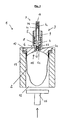
- a collapsible foil bag 2 as a container which is filled with a fluid, for example a liquid, pharmaceutical or cosmetic product.
- the film bag 2 is, as will be explained in more detail below, sealed to a pump 3, which in the illustrated embodiment comprises a pressure chamber 4 with a piston 5 sliding therein and two check valves 6 and 7, respectively.
- a spring 8 is provided in the pressure chamber 4, such that the piston 5 is acted upon in the figure upwards.
- the piston 5 has a central passage opening 9, through which a fluid can be pumped from the foil bag 2 into the environment.
- the first check valve 6 is connected such that this check valve 6 allows a flow from the foil bag 2 into the pressure chamber 4, when the spherical valve element 6a is lifted against the force of the valve spring 6b by a negative pressure in the pressure chamber 4 of its valve seat 6c. In the opposite direction, however, a flow from the pressure chamber 4 into the foil bag 2 through the first check valve 6 is blocked.
- the second check valve 7 is arranged so that at an overpressure in the pressure chamber 4 fluid can escape through the check valve 7 into the environment by the valve body 7a is lifted against the force of the valve spring 7b of its valve seat 7c. By contrast, a backflow of, for example, ambient air into the pressure chamber 4 is prevented by the check valve 7.
- the second check valve 7 is shown in the figure as part of the pump 3. Deviating from this, the second check valve may also be associated with a delivery head which can be fastened to the pump 3. In this case, the second valve does not have to be formed as shown in the figure but can also be like in the DE 101 08 486 A1 be designed described.
- the foil bag 2 is provided in the illustrated embodiment with an example. Stiffened cover 10, which seals the pump 3 against the foil bag 2.
- the cover 10 may be cast on the pump 3 or welded thereto.
- a peripheral edge of the collapsible foil bag 2 may be welded, glued or otherwise sealingly connected to an edge region of the rigid lid 10.
- the foil bag 2 is accommodated in, for example, a likewise rigid container (casing) 11, which is firmly or detachably connected to the lid 10.
- a bottom opening 12 is provided, so that the film bag 2 can freely expand or contract within the container 11, without this being hindered by an overpressure or underpressure in the container 11.
- the pump 3 has a lower in the figure suction port 13, which opens into the foil bag 2, and an upper outlet opening 14 in the figure, which communicates with the environment.
- the pump 3 and the suction opening 13 are arranged on the foil bag 2 or the cover 10 in such a way that the suction opening 13 in the embodiment shown does not or at most projects minimally beyond the lid 10 into the foil bag 2.
- a recess 15 is formed in the lid 10, in which an optionally existing in the foil bag 2 air bubble can accumulate with residual air.
- the depth of the recess 15 increases continuously from the edge of the lid 10 to the center of the lid 10, in which the suction port 13 of the pump 3 is arranged.
- the edge of the lid 10 protruding into the foil bag 2 is applied to the foil bag 2 and optionally connected to it.
- the metering pump assembly In the illustrated in the figure upright position of the metering pump assembly so collects the entire residual air inevitably in the vicinity of the suction port 13 of the pump 3 and can be discharged through this.
- a negative pressure is applied to the outlet opening 14, so that the valve bodies 6a and 6b rise against the force of the valve springs 6b and 7b from their valve seats 6c and 7c and the air through the suction opening 13 through the pump 3 to the outlet opening 14th can be sucked off.
- a punch 16 or the like Be introduced into the container 11, which compresses the film bag 2. Due to the overpressure in the container 11, the residual air is also expelled by the pump 3, whereby the valve body 6a and 7a stand against the force of the valve springs 6b and 7b of their valve seats 6c and 7c.
- the dispensing head As soon as fluid is sucked through the suction opening 13 and exits through the outlet opening 14, there is no residual air in the foil bag 2 and the pump 3 or the dispensing head.
- the two check valves 6 and 7 close again by the force of the valve springs 6b and 7b, so that no ambient air in the container 2 can flow back.
- the extraction of the residual air can, for example, take place in that a suction bell, not shown in the figure, at least the outlet opening 14 sealingly surrounds.
- the suction bell can also be placed on the lid 10, that the entire pump 3 is accommodated in the suction bell.
- the second check valve is provided in a discharge head (not shown in the figure), the residual air can be sucked out of the container 2 either before or after the placement of the delivery head.
- the first check valve 6 opens in the suction and prevents after the suction backflow of air into the container 2.
- both check valves 6, 7th are open with attached delivery head during the suction as described above, both check valves 6, 7th
- the central passage opening 9 of the pump 3 and the discharge head are filled after complete expulsion of the residual air from the metering pump assembly 1 with the product when the pressure in the container 11 remains established. In this way, a user can already remove the flowable product with the first pump stroke and does not have to first fill the pump 3 by several pump strokes before the first use of the dosing pump arrangement 1.
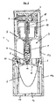
- FIG. 2 shows a further preferred embodiment of a metering pump arrangement 1 according to the invention, which is constructed similarly to the embodiment according to FIG. The function of this metering pump arrangement 1 also takes place in the manner described above with reference to FIG. Identical components are identified in this embodiment by the same reference numerals.
- the container (sleeve) accommodating the film bag 2 is formed in two parts with a partially double-walled container lower part 11a and a container upper part 11b fastened thereto by a latching connection, wherein the container upper part 11b receives the pump 3 and guides the piston 5.
- This construction allows a particularly easily produced by injection molding geometry of the container.
- the lower opening 12 in FIG. 2 for a piston or the like can be closed off after removal of the residual air from the foil bag 2 by a cover 17, in which a vent opening is again provided.
- the pump itself can by a protective cap 18, which on the container top 11 b can be plugged, are releasably closed after the residual air has been removed from the foil bag 2.
- the pressure chamber 4 forming body and the lid 10 are formed and adapted to each other, that these components are also connected by the engagement of the container upper part 11 b on the container base 11 a sealingly.
- a head 19 connected to the piston 5 is provided in the embodiment according to FIG. 2, which head is attached to the container top part 11 b.
- the stroke of the piston 5 is limited in this way.
- the second check valve 7 is provided, which has a nozzle for dispensing drops in the embodiment of Figure 2.
- the film bag 2 for removing the residual air for example, by means of a piston or the like. Compress, so as to expel the residual air from the foil bag and the pump 3.
Landscapes
- Containers And Packaging Bodies Having A Special Means To Remove Contents (AREA)
- Closures For Containers (AREA)
Applications Claiming Priority (2)
| Application Number | Priority Date | Filing Date | Title |
|---|---|---|---|
| DE102005022044 | 2005-04-21 | ||
| DE102005043839A DE102005043839B4 (de) | 2005-09-13 | 2005-09-13 | Verfahren zur Herstellung einer befüllten Dosierpumpenanordnung und Dosierpumpenanordnung |
Publications (2)
| Publication Number | Publication Date |
|---|---|
| EP1714706A2 true EP1714706A2 (fr) | 2006-10-25 |
| EP1714706A3 EP1714706A3 (fr) | 2009-12-09 |
Family
ID=36677163
Family Applications (1)
| Application Number | Title | Priority Date | Filing Date |
|---|---|---|---|
| EP06007343A Withdrawn EP1714706A3 (fr) | 2005-04-21 | 2006-04-07 | Pompe de dosage et procédé de fabrication d'une telle pompe remplie |
Country Status (2)
| Country | Link |
|---|---|
| US (1) | US20060255072A1 (fr) |
| EP (1) | EP1714706A3 (fr) |
Cited By (1)
| Publication number | Priority date | Publication date | Assignee | Title |
|---|---|---|---|---|
| EP3025612A4 (fr) * | 2013-07-25 | 2017-03-29 | AMG Co., Ltd. | Réceptacle pour produit cosmétique |
Families Citing this family (13)
| Publication number | Priority date | Publication date | Assignee | Title |
|---|---|---|---|---|
| FR2922528B1 (fr) * | 2007-10-23 | 2010-03-26 | Rexam Dispensing Smt | Pompe de distribution d'un liquide contenu dans un flacon |
| DE102008027987A1 (de) * | 2008-03-04 | 2009-09-17 | Kist-Europe Forschungsgesellschaft Mbh | Dosierungsvorrichtung |
| DE102009049902A1 (de) * | 2009-10-13 | 2011-04-14 | Ing. Erich Pfeiffer Gmbh | Austragvorrichtung |
| US9174231B2 (en) * | 2011-10-27 | 2015-11-03 | Graco Minnesota Inc. | Sprayer fluid supply with collapsible liner |
| AU2014253997B2 (en) * | 2013-04-16 | 2019-01-03 | Aerami Therapeutics, Inc. | Liquid dispensing and methods for dispensing liquids |
| ES2734570T3 (es) * | 2013-04-16 | 2019-12-10 | Dance Biopharm Inc | Distribución de líquido |
| FR3016815B1 (fr) * | 2014-01-30 | 2018-03-09 | Lablabo | Dispositif de conditionnement et de distribution de produits pateux |
| US9796492B2 (en) | 2015-03-12 | 2017-10-24 | Graco Minnesota Inc. | Manual check valve for priming a collapsible fluid liner for a sprayer |
| US20160377067A1 (en) * | 2015-06-29 | 2016-12-29 | Pentair Filtration Solutions, Llc | Fluid Dispensing Apparatus and Method |
| ES2755807A1 (es) | 2018-10-22 | 2020-04-23 | Disarp S A | Dispositivo dispensador para liquidos |
| CN115739435A (zh) | 2019-05-31 | 2023-03-07 | 固瑞克明尼苏达有限公司 | 手持式流体喷雾器 |
| CN112061444B (zh) * | 2020-09-09 | 2021-12-07 | 台州市亿源塑业有限公司 | 一种液体自动包装机 |
| KR102609420B1 (ko) * | 2021-07-30 | 2023-12-04 | 펌텍코리아 (주) | 액상 내용물 토출 용기 |
Citations (5)
| Publication number | Priority date | Publication date | Assignee | Title |
|---|---|---|---|---|
| US5144788A (en) | 1988-06-28 | 1992-09-08 | Valois S.A. | Method of vacuum-packing a liquid or a paste in a flexible tube having a dispensing pump or valve |
| WO1993022200A1 (fr) | 1992-04-30 | 1993-11-11 | Norden Pac Development Ab | Procede de fabrication d'un recipient pratiquement depourvu d'air |
| DE10108486A1 (de) | 2001-02-22 | 2002-09-19 | Steven Padar | Abgabevorrichtung für Fluide |
| DE10049898C2 (de) | 2000-10-10 | 2002-10-02 | Steven Padar | Abgabevorrichtung für Fluide |
| DE69332089T2 (de) | 1992-11-23 | 2003-02-06 | Hygiene-Technik Inc., Beamsville | Evakuierungsmethode |
Family Cites Families (11)
| Publication number | Priority date | Publication date | Assignee | Title |
|---|---|---|---|---|
| US2096397A (en) * | 1935-03-07 | 1937-10-19 | Harris Frederick George | Method of and means for handling soap paste, grease, and other materials of like consistency |
| US4457455A (en) * | 1981-10-13 | 1984-07-03 | Philip Meshberg | Collapsible container |
| DE3432253A1 (de) * | 1984-09-01 | 1986-03-13 | Coronet - Werke Heinrich Schlerf Gmbh, 6948 Wald-Michelbach | Spender fuer fluessige oder pastoese medien |
| EP0446513B1 (fr) * | 1990-03-16 | 1994-11-02 | Kabushiki Kaisha Top | Pompe |
| FR2684901B1 (fr) * | 1991-12-13 | 1994-02-25 | Conceptair Anstalt | Procede et dispositif evitant la formation de poches gazeuses dans un reservoir pour un produit fluide destine a etre pulverise ou distribue sans reprise d'air |
| US5449094A (en) * | 1992-05-18 | 1995-09-12 | Sofab | Dispenser with plunging sleeve |
| US5842605A (en) * | 1996-07-24 | 1998-12-01 | Lehmkuhl; Robert A. | Resuable dispenser for paste, lotion and cream-like materials |
| FR2776628B1 (fr) * | 1998-03-27 | 2000-05-12 | Oreal | Ensemble de conditionnement et de distribution d'un produit liquide |
| FR2788500B1 (fr) * | 1999-01-20 | 2001-03-02 | Oreal | Ensemble de conditionnement et de distribution d'un produit equipe d'une pompe et d'un reservoir souple |
| FR2821339B1 (fr) * | 2001-02-28 | 2003-08-01 | Airlessystems | Distributeur de produit fluide a poche souple et procede de fabrication d'une telle poche souple |
| DE10234417A1 (de) * | 2002-07-29 | 2004-02-12 | Alfred Von Schuckmann | Spender für pastöse bis fließfähige Massen |
-
2006
- 2006-04-07 EP EP06007343A patent/EP1714706A3/fr not_active Withdrawn
- 2006-04-20 US US11/408,218 patent/US20060255072A1/en not_active Abandoned
Patent Citations (5)
| Publication number | Priority date | Publication date | Assignee | Title |
|---|---|---|---|---|
| US5144788A (en) | 1988-06-28 | 1992-09-08 | Valois S.A. | Method of vacuum-packing a liquid or a paste in a flexible tube having a dispensing pump or valve |
| WO1993022200A1 (fr) | 1992-04-30 | 1993-11-11 | Norden Pac Development Ab | Procede de fabrication d'un recipient pratiquement depourvu d'air |
| DE69332089T2 (de) | 1992-11-23 | 2003-02-06 | Hygiene-Technik Inc., Beamsville | Evakuierungsmethode |
| DE10049898C2 (de) | 2000-10-10 | 2002-10-02 | Steven Padar | Abgabevorrichtung für Fluide |
| DE10108486A1 (de) | 2001-02-22 | 2002-09-19 | Steven Padar | Abgabevorrichtung für Fluide |
Cited By (1)
| Publication number | Priority date | Publication date | Assignee | Title |
|---|---|---|---|---|
| EP3025612A4 (fr) * | 2013-07-25 | 2017-03-29 | AMG Co., Ltd. | Réceptacle pour produit cosmétique |
Also Published As
| Publication number | Publication date |
|---|---|
| EP1714706A3 (fr) | 2009-12-09 |
| US20060255072A1 (en) | 2006-11-16 |
| HK1098100A1 (zh) | 2007-07-13 |
Similar Documents
| Publication | Publication Date | Title |
|---|---|---|
| DE69515778T2 (de) | Pumpe ohne Restvolumen zur Abgabe von Medien | |
| DE60306421T2 (de) | Manuell betätigte dosierpumpe | |
| EP2605857B1 (fr) | Module de distribution | |
| EP2605858B1 (fr) | Module de distribution et procédé pour remplir un module de distribution | |
| EP1714706A2 (fr) | Pompe de dosage et procédé de fabrication d'une telle pompe remplie | |
| EP2018227B1 (fr) | Dispositif de distribution | |
| DE4027749A1 (de) | Austragvorrichtung fuer medien | |
| EP1038796A2 (fr) | Conteneur pour matière pâteuse ou fluide et sa distribution dosée | |
| EP3806938B1 (fr) | Système, cartouche et procédé | |
| EP1717159B1 (fr) | Procédé de fabrication d'un ensemble pré-rempli à pompe doseuse | |
| DE102011106261A1 (de) | Spender zur dosierten Abgabe von flüssigen Medien | |
| DE202006017793U1 (de) | Pneumatischer Flüssigkeitsspender mit doppelwandigem Behälter | |
| DE602004005611T2 (de) | Pumpe zur abgabe von fluidprodukten | |
| WO2019015893A1 (fr) | Distributeur de fluide | |
| EP1588772B1 (fr) | Pompe de dosage et son procédé de fabrication | |
| EP1871539B1 (fr) | Distributeur utilise pour la distribution des masses fluides et pateuses | |
| EP3432951B1 (fr) | Cartouche de dosage de gouttes | |
| DE102005043839B4 (de) | Verfahren zur Herstellung einer befüllten Dosierpumpenanordnung und Dosierpumpenanordnung | |
| DE202006002873U1 (de) | Dosierpumpenanordnung | |
| DE202006020471U1 (de) | Dosierpumpenanordnung | |
| DE69202356T2 (de) | Vorrichtung zur Zerstäubung oder Abgabe eines flüssigen Produktes mit einem Schiebeteil in ihrem Saugrohr. | |
| DE60223671T2 (de) | Dosierpumpe | |
| DE202014003991U1 (de) | Druckluft getriebener Spender | |
| EP4410438B1 (fr) | Système de cartouche pour la distribution d'une solution aqueuse | |
| EP1630417B1 (fr) | Dipositif pour délivrer des fluides, des liquides et des matériaux visqueux |
Legal Events
| Date | Code | Title | Description |
|---|---|---|---|
| PUAI | Public reference made under article 153(3) epc to a published international application that has entered the european phase |
Free format text: ORIGINAL CODE: 0009012 |
|
| AK | Designated contracting states |
Kind code of ref document: A2 Designated state(s): AT BE BG CH CY CZ DE DK EE ES FI FR GB GR HU IE IS IT LI LT LU LV MC NL PL PT RO SE SI SK TR |
|
| AX | Request for extension of the european patent |
Extension state: AL BA HR MK YU |
|
| PUAL | Search report despatched |
Free format text: ORIGINAL CODE: 0009013 |
|
| AK | Designated contracting states |
Kind code of ref document: A3 Designated state(s): AT BE BG CH CY CZ DE DK EE ES FI FR GB GR HU IE IS IT LI LT LU LV MC NL PL PT RO SE SI SK TR |
|
| AX | Request for extension of the european patent |
Extension state: AL BA HR MK YU |
|
| AKY | No designation fees paid | ||
| STAA | Information on the status of an ep patent application or granted ep patent |
Free format text: STATUS: THE APPLICATION IS DEEMED TO BE WITHDRAWN |
|
| 18D | Application deemed to be withdrawn |
Effective date: 20100610 |
|
| REG | Reference to a national code |
Ref country code: DE Ref legal event code: 8566 |