EP1714831A1 - Fahrzeugscheinwerfereinrichtung - Google Patents
Fahrzeugscheinwerfereinrichtung Download PDFInfo
- Publication number
- EP1714831A1 EP1714831A1 EP06008229A EP06008229A EP1714831A1 EP 1714831 A1 EP1714831 A1 EP 1714831A1 EP 06008229 A EP06008229 A EP 06008229A EP 06008229 A EP06008229 A EP 06008229A EP 1714831 A1 EP1714831 A1 EP 1714831A1
- Authority
- EP
- European Patent Office
- Prior art keywords
- unit
- control unit
- electric control
- headlight
- signal
- Prior art date
- Legal status (The legal status is an assumption and is not a legal conclusion. Google has not performed a legal analysis and makes no representation as to the accuracy of the status listed.)
- Granted
Links
- 230000005856 abnormality Effects 0.000 claims abstract description 23
- 230000001678 irradiating effect Effects 0.000 claims description 12
- 230000008859 change Effects 0.000 claims description 8
- 238000001514 detection method Methods 0.000 claims description 8
- 230000003287 optical effect Effects 0.000 claims description 8
- 238000004891 communication Methods 0.000 description 11
- 230000007812 deficiency Effects 0.000 description 2
- 238000010586 diagram Methods 0.000 description 2
- 230000004313 glare Effects 0.000 description 2
- 230000007935 neutral effect Effects 0.000 description 2
- 230000003044 adaptive effect Effects 0.000 description 1
- 230000005540 biological transmission Effects 0.000 description 1
- 238000005266 casting Methods 0.000 description 1
- 238000010276 construction Methods 0.000 description 1
- 230000003247 decreasing effect Effects 0.000 description 1
- 230000000694 effects Effects 0.000 description 1
- 238000005516 engineering process Methods 0.000 description 1
- 230000007246 mechanism Effects 0.000 description 1
- 238000012986 modification Methods 0.000 description 1
- 230000004048 modification Effects 0.000 description 1
- 230000002265 prevention Effects 0.000 description 1
Images

Classifications
-
- B—PERFORMING OPERATIONS; TRANSPORTING
- B60—VEHICLES IN GENERAL
- B60Q—ARRANGEMENT OF SIGNALLING OR LIGHTING DEVICES, THE MOUNTING OR SUPPORTING THEREOF OR CIRCUITS THEREFOR, FOR VEHICLES IN GENERAL
- B60Q1/00—Arrangement of optical signalling or lighting devices, the mounting or supporting thereof or circuits therefor
- B60Q1/02—Arrangement of optical signalling or lighting devices, the mounting or supporting thereof or circuits therefor the devices being primarily intended to illuminate the way ahead or to illuminate other areas of way or environments
- B60Q1/04—Arrangement of optical signalling or lighting devices, the mounting or supporting thereof or circuits therefor the devices being primarily intended to illuminate the way ahead or to illuminate other areas of way or environments the devices being headlights
- B60Q1/06—Arrangement of optical signalling or lighting devices, the mounting or supporting thereof or circuits therefor the devices being primarily intended to illuminate the way ahead or to illuminate other areas of way or environments the devices being headlights adjustable, e.g. remotely-controlled from inside vehicle
- B60Q1/08—Arrangement of optical signalling or lighting devices, the mounting or supporting thereof or circuits therefor the devices being primarily intended to illuminate the way ahead or to illuminate other areas of way or environments the devices being headlights adjustable, e.g. remotely-controlled from inside vehicle automatically
- B60Q1/12—Arrangement of optical signalling or lighting devices, the mounting or supporting thereof or circuits therefor the devices being primarily intended to illuminate the way ahead or to illuminate other areas of way or environments the devices being headlights adjustable, e.g. remotely-controlled from inside vehicle automatically due to steering position
-
- B—PERFORMING OPERATIONS; TRANSPORTING
- B60—VEHICLES IN GENERAL
- B60Q—ARRANGEMENT OF SIGNALLING OR LIGHTING DEVICES, THE MOUNTING OR SUPPORTING THEREOF OR CIRCUITS THEREFOR, FOR VEHICLES IN GENERAL
- B60Q11/00—Arrangement of monitoring devices for devices provided for in groups B60Q1/00 - B60Q9/00
-
- B—PERFORMING OPERATIONS; TRANSPORTING
- B60—VEHICLES IN GENERAL
- B60Q—ARRANGEMENT OF SIGNALLING OR LIGHTING DEVICES, THE MOUNTING OR SUPPORTING THEREOF OR CIRCUITS THEREFOR, FOR VEHICLES IN GENERAL
- B60Q2200/00—Special features or arrangements of vehicle headlamps
- B60Q2200/30—Special arrangements for adjusting headlamps, e.g. means for transmitting the movements for adjusting the lamps
- B60Q2200/38—Automatic calibration of motor-driven means for adjusting headlamps, i.e. when switching on the headlamps, not during mounting at factories
-
- B—PERFORMING OPERATIONS; TRANSPORTING
- B60—VEHICLES IN GENERAL
- B60Q—ARRANGEMENT OF SIGNALLING OR LIGHTING DEVICES, THE MOUNTING OR SUPPORTING THEREOF OR CIRCUITS THEREFOR, FOR VEHICLES IN GENERAL
- B60Q2300/00—Indexing codes for automatically adjustable headlamps or automatically dimmable headlamps
- B60Q2300/05—Special features for controlling or switching of the light beam
- B60Q2300/054—Variable non-standard intensity, i.e. emission of various beam intensities different from standard intensities, e.g. continuous or stepped transitions of intensity
-
- B—PERFORMING OPERATIONS; TRANSPORTING
- B60—VEHICLES IN GENERAL
- B60Q—ARRANGEMENT OF SIGNALLING OR LIGHTING DEVICES, THE MOUNTING OR SUPPORTING THEREOF OR CIRCUITS THEREFOR, FOR VEHICLES IN GENERAL
- B60Q2300/00—Indexing codes for automatically adjustable headlamps or automatically dimmable headlamps
- B60Q2300/10—Indexing codes relating to particular vehicle conditions
- B60Q2300/11—Linear movements of the vehicle
- B60Q2300/112—Vehicle speed
-
- B—PERFORMING OPERATIONS; TRANSPORTING
- B60—VEHICLES IN GENERAL
- B60Q—ARRANGEMENT OF SIGNALLING OR LIGHTING DEVICES, THE MOUNTING OR SUPPORTING THEREOF OR CIRCUITS THEREFOR, FOR VEHICLES IN GENERAL
- B60Q2300/00—Indexing codes for automatically adjustable headlamps or automatically dimmable headlamps
- B60Q2300/10—Indexing codes relating to particular vehicle conditions
- B60Q2300/12—Steering parameters
- B60Q2300/122—Steering angle
-
- B—PERFORMING OPERATIONS; TRANSPORTING
- B60—VEHICLES IN GENERAL
- B60Q—ARRANGEMENT OF SIGNALLING OR LIGHTING DEVICES, THE MOUNTING OR SUPPORTING THEREOF OR CIRCUITS THEREFOR, FOR VEHICLES IN GENERAL
- B60Q2300/00—Indexing codes for automatically adjustable headlamps or automatically dimmable headlamps
- B60Q2300/10—Indexing codes relating to particular vehicle conditions
- B60Q2300/14—Other vehicle conditions
- B60Q2300/144—Rearward ratio actuation
-
- B—PERFORMING OPERATIONS; TRANSPORTING
- B60—VEHICLES IN GENERAL
- B60Q—ARRANGEMENT OF SIGNALLING OR LIGHTING DEVICES, THE MOUNTING OR SUPPORTING THEREOF OR CIRCUITS THEREFOR, FOR VEHICLES IN GENERAL
- B60Q2300/00—Indexing codes for automatically adjustable headlamps or automatically dimmable headlamps
- B60Q2300/10—Indexing codes relating to particular vehicle conditions
- B60Q2300/14—Other vehicle conditions
- B60Q2300/146—Abnormalities, e.g. fail-safe
Definitions
- the present invention relates to a vehicle headlight device (a vehicle headlight system) that changes an irradiating direction of light from a headlight unit according to a state of a vehicle.
- a conventional vehicle headlight device that changes an irradiating direction of light from a headlight unit according to, for example, a running state of a vehicle, such as an adaptive front lighting system (AFS), is described in, for example, Japanese Patent Application Laid-Open No. 2004-106770 .
- the conventional vehicle headlight device detects a running state of a vehicle with a sensor and outputs a detection signal of the sensor to a main central processing unit (CPU) (a master electric control unit (ECU)).
- the main CPU calculates a rotation angle of a swivel lamp (a headlight unit) based on the detection signal and outputs data of the rotation angle to a sub-CPU (a slave ECU).
- the sub CPU drives an actuator (a driving unit) based on the rotation angle data.
- the actuator rotates the swivel lamp. This makes it possible to change an irradiating direction of light from the swivel lamp.
- a device that sets an optical axis of the swivel lamp in a reference angle position i.e., an initial-position setting device of the headlight unit. Consequently, the conventional vehicle headlight device can grasp an initial position of the swivel lamp. This makes it possible to accurately change an irradiating direction of light from the swivel lamp according to a running state of a vehicle.
- Fig. 1 is a block diagram of a vehicle headlight device according to an embodiment of the present invention.
- the vehicle headlight device includes a projector unit (a headlight unit) 5, a driving unit (a swivel actuator unit) 4, a vehicle sensor 1, a master ECU 2, and a slave ECU 3.
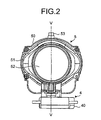
- the projector unit 5 is arranged on each of the left side and the right side in a front portion of a vehicle (not shown) to be rotatable around a substantially vertical axis V-V.
- the projector unit 5 is a lamp unit of a projector type.
- the projector unit 5 includes a light source (not shown), a reflector 50, a frame 51, a projection lens 52, and a rotation shaft 53 (the upper side of the rotation shaft 53 is shown and the lower side of the rotation shaft 53 is not shown in the figure).
- the rotation shaft 53 is supported by a bearing (not shown) to be rotatable around the substantially vertical axis V-V.
- the projector unit 5 when the light source is turned on, light from the light source is reflected on the reflector 50 and the reflected light is projected through the projection lens 52 to illuminate a road surface or the like.
- the projector unit 5 is made of a headlight unit like a headlamp or a fog lamp.
- the projector unit 5 may be a lamp unit of a type other than the projector type.
- the driving unit 4 rotates the projector unit around the substantially vertical axis V-V to change an irradiating direction of light from the projector unit.
- the driving unit 4 is arranged on each of the left side and the right side in the front portion of the vehicle.
- the driving unit 4 includes a casing 40, a stepping motor 4a and a position detecting sensor 4b arranged in the casing 40, and an initial position setting unit (not shown) for setting an initial position of the projector unit 5.
- the stepping motor 4a is coupled to the rotation shaft 53 via a torque transmission mechanism (not shown).
- the stepping motor 4a is driven based on drive control by the slave ECU 3 and rotates (swivels) the projector unit 5 around the substantially vertical axis V-V to change an irradiating direction of light from the projector unit 5.
- the position detecting sensor 4b detects a rotating position of the projector unit 5 and outputs a detection signal for the rotating position to the slave ECU 3.
- the vehicle sensor 1 detects a running state of the vehicle and outputs a vehicle signal.
- the vehicle sensor 1 includes a steering angle sensor, a headlamp switch, a vehicle speed sensor, and a reverse sensor.
- the steering angle sensor detects a steering angle (synonymous with a rudder angle) of a steering handle (not shown; synonymous with a steering wheel, a handle, and the like) and a steering direction and outputs a steering angle signal and a steering direction signal to the master ECU 2.
- the steering angle sensor detects a steering angle (a rotation angle) and a steering direction (a rotating direction) of a steering handle operated by a driver and outputs a steering angle signal and a steering direction signal to the master ECU 2.
- the steering angle signal and the steering direction signal are obtained as specific numerical value data.
- the specific numerical value data is obtained as numerical value data of +10° when the steering handle is turned 10° to the right and is obtained as numerical value data of -10° when the steering handle is turned 10° to the left.
- the specific numerical value data is obtained as numerical value data of "990" with respect to a neutral numerical value of "1000" when the steering handle is turned 10° to the right and is obtained as numerical value data of "1010” with respect to the neutral numerical value of "1000" when the steering handle is turned 10° to the left.
- the steering angle signal and the steering direction signal may be obtained as, for example, electric signals output to the master ECU 2 by the steering angle sensor (e.g., an optical sensor) mounted on the vehicle.
- the head lamp switch is turned on and off by the driver to turn on and off the headlamp or the like (not shown).
- the headlamp switch When the headlamp switch is on, the headlamp switch outputs an ON signal (e.g., a high level signal) to the master ECU 2.
- the headlamp switch When the headlamp switch is off, the headlamp switch outputs an OFF signal (e.g., a low level signal) to the master ECU 2.
- the vehicle speed sensor detects vehicle speed and outputs a vehicle speed signal to the master ECU 2.
- the reverse sensor detects a reverse position among shift positions of a shift lever (not shown) and outputs a reverse signal to the master ECU 2.
- the master ECU 2 calculates a rotation angle (a swivel angle) of the projector unit 5 based on a vehicle signal from the vehicle sensor 1 and outputs rotation angle data to the slave ECU 3.
- the master ECU 2 is arranged in a driver's seat cab or near the driver's seat cab. As shown in Fig. 1, the master ECU 2 includes a power-supply reset circuit 2a, an input interface (I/F) 2b, a microcontroller 2c, a communication interface (I/F) 2d, and a second signal output circuit 2e.
- the power-supply reset circuit 2a resets a power supply for the microcontroller 2c when the power-supply reset circuit 2a detects abnormality of the microcontroller 2c in the master ECU 2.
- the input I/F 2b is connected to the vehicle sensor 1.
- the input I/F 2b is input with a vehicle signal from the vehicle sensor 1 and outputs (transfers) the vehicle signal to the microcontroller 2c.
- the microcontroller 2c calculates a rotation angle of the projector unit 5 based on the vehicle signal input from the input I/F 2b and outputs (transfers) rotation angle data to the communication I/F 2d.
- the communication I/F 2d outputs (transmits) the rotation angle data input from the microcontroller 2c to the slave ECU 3.
- the slave ECU 3 drives the driving unit 4 based on the rotation angle data from the master ECU 2 to change an irradiating direction of light from the projector unit 5.
- the slave ECU 3 is arranged in the driving unit 4 or near the driving unit 4 or in the projector unit 5 or near the projector unit 5.
- the slave ECU 3 includes a power-supply reset circuit 3a, a communication interface (I/F) 3b, a microcontroller 3c, a motor driver 3d, a sensor interface (I/F) 3e, a second signal output circuit 3f, a lamp driver 3g, and an optical-axis control unit 3h.
- the power-supply reset circuit 3a resets a power supply for the microcontroller 3c when the power-supply reset circuit 3a detects abnormality of the microcontroller 3c in the slave ECU 3.
- the communication I/F 3b is connected to the communication I/F 2d of the master ECU 2.
- the communication I/F 3b is input with (receives) rotation angle data from the master ECU 2 and outputs the rotation angle data to the microcontroller 3c.
- the microcontroller 3c outputs a motor drive control signal to the motor driver 3d based on the rotation angle data input from the communication I/F 3b.
- the microcontroller 3c grasps a position of the projector unit 5 based on a position signal input from the sensor I/F 3e.
- the motor driver 3d controls driving of the stepping motor 4a based on the motor drive control signal input from the microcontroller 3c.
- the sensor I/F 3e is connected to the position detecting sensor 4b.
- the sensor I/F 3e is input with a position detection signal from the position detecting sensor 4b and outputs (transfers) the position detection signal to the microcontroller 3c.
- a circuit that outputs an abnormality occurrence signal to the master ECU 2 when abnormality occurs, that is, the second signal output circuit 3f is provided in the slave ECU 3.
- a circuit that outputs a projector-unit-initial-position-setting-operation instruction signal to the slave ECU 3 based on the abnormality occurrence signal from the slave ECU 3, that is, the second signal output circuit 2e is provided in the master ECU 2.
- the lamp driver 3g that subjects a light amount of a power supply for the projector unit 5 to dimming control is provided in the slave ECU 3.
- An optical-axis adjusting unit 6 that adjusts an optical axis of the projector unit 5 is provided in the projector unit 5.
- the optical-axis control unit 3h that adjusts the optical axis of the projector unit 5 via the optical-axis adjusting unit 6 is provided in the slave ECU 3.
- the master ECU 2 and the slave ECU 3 are connected by one signal line 7.
- the slave ECU 3 and the driving unit 4 or the projector unit 5 are connected by a plurality of signal lines 8.
- the motor driver 3d of the slave ECU 3 and the stepping motor 4a of the driving unit 4 are connected by the signal line 8.
- the sensor I/F 3e of the slave ECU 3 and the position detecting sensor 4b of the driving unit 4 are connected by the signal line 8.
- the lamp driver 3g of the slave ECU 3 and the projector unit 5 are connected by the signal line 8.
- the optical-axis control unit 3h of the slave ECU 3 and the optical-axis adjusting unit 6 are connected by the signal line 8.
- the vehicle headlight device according to the present embodiment has the constitution described above. Actions of the vehicle headlight device according to the present embodiment are explained below.
- a power supply to the master ECU 2 and the slave ECU 3 is turned on to start the vehicle headlight device according to the present embodiment.
- the master ECU 2 and the slave ECU 3 perform an operation for setting an initial position of the projector unit 5 (an initialize operation) first.
- the master ECU 2 outputs a projector-unit-initial-position-setting-operation instruction signal to the slave ECU 3 via the communication I/Fs 2d and 3b.
- the slave ECU 3 input with the projector-unit-initial-position-setting-operation instruction signal performs an operation for setting an initial position of the projector unit 5.
- the slave ECU 3 rotates the stepping motor 4a in one direction to a position where the initial position setting unit in the casing 40 of the driving unit 4 mechanically interferes with the stepping motor 4a to intentionally regulate the initial position setting unit.
- the slave ECU 3 stops the rotation in one direction of the stepping motor 4a and rotates to return the stepping motor 4a in the opposite direction by a predetermined pulse. Consequently, the projector unit 5 is set in the initial position. According to the initialize operation, the slave ECU 3 can grasp the initial position of the projector unit 5.
- the master ECU 2 and the slave ECU 3 perform a normal operation.
- the normal operation is explained below.
- Vehicle signals are input from the vehicle sensor 1 to the microcontroller 2c via the input I/F 2b in the master ECU 2.
- a steering angle signal and a steering direction signal are input from the steering angle sensor.
- An ON signal and an OFF signal are input from the headlamp switch.
- a vehicle speed signal is input from the vehicle speed sensor.
- a reverse signal is input from the reverse sensor.
- the microcontroller 2c calculates an angle for rotating the projector unit 5 based on the vehicle signal input and outputs the rotation angle calculated to the slave ECU 3 via the communication I/F 2d as rotation angle data.
- the rotation angle data is input from the master ECU 2 to the microcontroller 3c via the communication I/F 3b in the slave ECU 3.
- the microcontroller 3c outputs a motor drive control signal to the motor driver 3d based on the rotation angle data input.
- the motor driver 3d drives the stepping motor 4a of the driving unit 4 based on the motor drive control signal input.
- the projector unit 5 rotates to the calculated angle according to the driving of the stepping motor 4a.
- the position detecting sensor 4b detects a rotating position of the projector unit 5 and outputs a position detection signal for the rotating position to the slave ECU 3.
- the slave ECU 3 stops the driving of the stepping motor 4a. This makes it possible to cause an irradiating direction of light from the projector unit 5 to follow a state of the vehicle.
- the power-supply reset circuit 3a When power supply abnormality (a low voltage, etc.) or microcomputer runaway (a watchdog function) occurs on the slave ECU 3 side, the power-supply reset circuit 3a operates to reset the microcontroller 3c.
- the microcontroller 3c When the microcontroller 3c is reset, the data of a rotating position of the projector unit 5 stored in the RAM or the like in the slave ECU 3 is reset. Therefore, the slave ECU 3 cannot grasp a present position of the projector unit 5, that is, a position at the time when the abnormality occurs on the slave ECU 3 side.
- the slave ECU 3 outputs an abnormality occurrence signal to the master ECU 2. Consequently, the master ECU 2 can grasp the occurrence of the abnormality on the slave ECU 3 side that cannot be grasped by the slave ECU 3.
- the master ECU 2 outputs a projector-unit-initial-position-setting-operation instruction signal to the slave ECU 3 based on the abnormality occurrence signal input from the slave ECU 3. Consequently, the initialize operation is performed again.
- the master ECU 2 and the slave ECU 3 return to the normal operation.
- the power supply to the master ECU 2 and the slave ECU 3 is turned off, the operation of the vehicle headlight device according to the present embodiment stops.
- the vehicle headlight device according to the present embodiment has the constitution and the actions described above. Effects of the vehicle headlight device according to the present embodiment are explained below.
- the slave ECU 3 when abnormality occurs in the slave ECU 3 and the slave ECU 3 is reset, the slave ECU 3 outputs an abnormality occurrence signal to the master ECU 2.
- the master ECU 2 outputs a projector-unit-initial-position-setting-operation instruction signal to the slave ECU 3. Therefore, in the vehicle headlight device according to the present embodiment, when abnormality occurs in the slave ECU 3 and the slave ECU 3 is reset, the master ECU 2 can grasp reset of the slave ECU 3. Moreover, the master ECU 2 can set an initial position of the projector unit 5. Consequently, in the vehicle headlight device according to the present embodiment, when the slave ECU 3 is reset, the master ECU 2 can grasp a position of the projector unit 5. Thus, it is possible to always accurately and surely control an irradiating direction of light from the projector unit 5. It is possible to contribute to traffic safety without casting glare at an oncoming car or the like.
- a control device is divided into the master ECU 2 and the slave ECU 3.
- the master ECU 2 on the driver side and the slave ECU 3 on the driving unit 4 side in the front portion of the vehicle with one signal line 7.
- the slave ECU 3 it is possible to cause the slave ECU 3 to perform dimming control for gradually increasing or gradually decreasing a light amount of the light source of the projector unit 5 via the lamp driver 3g. It is also possible to cause the slave ECU 3 to perform optical axis control for adjusting the optical axis of the projector unit 5 in an up-to-down direction (a vertical direction) via the optical-axis control unit 3h and the optical-axis adjusting unit (a leveling device) 6. Consequently, it is possible to reduce the number of long signal lines 7 wired between the master ECU 2 and the slave ECU 3 to one. On the other hand, it is possible to reduce the length of the large number of signal lines 8 wired between the slave ECU 3 and the projector unit 5.
- the vehicle headlight device includes a slave ECU, a driving unit, and a projector unit on the left side and a slave ECU, a driving unit, and a projector unit on the right side.
- a master ECU and the slave ECUs on the left side and the right side are connected in parallel.
- the master ECU and one slave ECU are connected and the master ECU is connected to the other slave ECU through one slave ECU.
Landscapes
- Engineering & Computer Science (AREA)
- Mechanical Engineering (AREA)
- Lighting Device Outwards From Vehicle And Optical Signal (AREA)
Applications Claiming Priority (1)
| Application Number | Priority Date | Filing Date | Title |
|---|---|---|---|
| JP2005122627A JP4333626B2 (ja) | 2005-04-20 | 2005-04-20 | 車両用前照灯装置 |
Publications (2)
| Publication Number | Publication Date |
|---|---|
| EP1714831A1 true EP1714831A1 (de) | 2006-10-25 |
| EP1714831B1 EP1714831B1 (de) | 2008-08-13 |
Family
ID=36928579
Family Applications (1)
| Application Number | Title | Priority Date | Filing Date |
|---|---|---|---|
| EP20060008229 Expired - Lifetime EP1714831B1 (de) | 2005-04-20 | 2006-04-20 | Fahrzeugscheinwerfereinrichtung |
Country Status (3)
| Country | Link |
|---|---|
| EP (1) | EP1714831B1 (de) |
| JP (1) | JP4333626B2 (de) |
| DE (1) | DE602006002159D1 (de) |
Cited By (1)
| Publication number | Priority date | Publication date | Assignee | Title |
|---|---|---|---|---|
| EP2090465A3 (de) * | 2008-02-13 | 2011-01-05 | Koito Manufacturing Co., Ltd | Fahrzeugscheinwerferkontrollsystem und -kontrollverfahren |
Families Citing this family (3)
| Publication number | Priority date | Publication date | Assignee | Title |
|---|---|---|---|---|
| JP4737113B2 (ja) * | 2007-02-23 | 2011-07-27 | パナソニック電工株式会社 | 配光可変型前照灯システム及び車載用前照灯灯具 |
| JP4968169B2 (ja) * | 2008-04-25 | 2012-07-04 | トヨタ自動車株式会社 | 通信システム及び通信方法 |
| JP7354654B2 (ja) * | 2019-07-30 | 2023-10-03 | マツダ株式会社 | 車両制御システム |
Citations (5)
| Publication number | Priority date | Publication date | Assignee | Title |
|---|---|---|---|---|
| DE19911901A1 (de) * | 1999-03-17 | 2000-10-05 | Daimler Chrysler Ag | Fahrzeugbeleuchtungsvorrichtung mit fahrsituationsabhängiger Beleuchtungssteuerung |
| US20020163815A1 (en) * | 2001-05-07 | 2002-11-07 | Toshihisa Hayami | Vehicle lighting apparatus |
| JP2004106770A (ja) | 2002-09-20 | 2004-04-08 | Koito Mfg Co Ltd | 車両用前照灯装置及びその光軸位置設定方法 |
| US20040085780A1 (en) * | 2002-11-05 | 2004-05-06 | Toshihisa Hayami | Vehicle headlamp apparatus |
| JP2005122627A (ja) | 2003-10-20 | 2005-05-12 | Ibiken Kk | 発注支援システム、及び発注支援プログラム |
-
2005
- 2005-04-20 JP JP2005122627A patent/JP4333626B2/ja not_active Expired - Fee Related
-
2006
- 2006-04-20 DE DE200660002159 patent/DE602006002159D1/de not_active Expired - Lifetime
- 2006-04-20 EP EP20060008229 patent/EP1714831B1/de not_active Expired - Lifetime
Patent Citations (5)
| Publication number | Priority date | Publication date | Assignee | Title |
|---|---|---|---|---|
| DE19911901A1 (de) * | 1999-03-17 | 2000-10-05 | Daimler Chrysler Ag | Fahrzeugbeleuchtungsvorrichtung mit fahrsituationsabhängiger Beleuchtungssteuerung |
| US20020163815A1 (en) * | 2001-05-07 | 2002-11-07 | Toshihisa Hayami | Vehicle lighting apparatus |
| JP2004106770A (ja) | 2002-09-20 | 2004-04-08 | Koito Mfg Co Ltd | 車両用前照灯装置及びその光軸位置設定方法 |
| US20040085780A1 (en) * | 2002-11-05 | 2004-05-06 | Toshihisa Hayami | Vehicle headlamp apparatus |
| JP2005122627A (ja) | 2003-10-20 | 2005-05-12 | Ibiken Kk | 発注支援システム、及び発注支援プログラム |
Cited By (2)
| Publication number | Priority date | Publication date | Assignee | Title |
|---|---|---|---|---|
| EP2090465A3 (de) * | 2008-02-13 | 2011-01-05 | Koito Manufacturing Co., Ltd | Fahrzeugscheinwerferkontrollsystem und -kontrollverfahren |
| US8134295B2 (en) | 2008-02-13 | 2012-03-13 | Koito Manufacturing Co., Ltd. | Vehicle lamp control system and control method |
Also Published As
| Publication number | Publication date |
|---|---|
| JP2006298160A (ja) | 2006-11-02 |
| EP1714831B1 (de) | 2008-08-13 |
| JP4333626B2 (ja) | 2009-09-16 |
| DE602006002159D1 (de) | 2008-09-25 |
Similar Documents
| Publication | Publication Date | Title |
|---|---|---|
| WO2004049123A2 (en) | Electronic intelligent turn signal control system | |
| US7057504B2 (en) | Vehicle headlamp apparatus | |
| US8134295B2 (en) | Vehicle lamp control system and control method | |
| EP1714831B1 (de) | Fahrzeugscheinwerfereinrichtung | |
| US7150547B2 (en) | Turn signal and steering responsive adjustable lighting apparatus for vehicle | |
| JP4290586B2 (ja) | 点灯装置および点灯システム | |
| JP3833822B2 (ja) | 車両前照灯制御装置 | |
| JP4197278B2 (ja) | 車両用照明装置 | |
| JP2002234383A (ja) | 可変配光ヘッドランプシステム | |
| KR20090114582A (ko) | 듀얼 헤드램프 시스템 | |
| JP4305297B2 (ja) | 車両用照明装置 | |
| KR20010065900A (ko) | 자동차의 조향용 보조라이트 | |
| JP4737075B2 (ja) | 車載用前照灯の配光制御装置及び車載用前照灯 | |
| CN222629201U (zh) | 警示装置和车辆 | |
| KR100471210B1 (ko) | 자동차의 방향지시 등화장치 | |
| EP2528774B1 (de) | Abschirmungsaktuator für scheinwerfer im fahrzeug | |
| CN1899879B (zh) | 可自动提供辅助转向照明的车灯 | |
| CN103692956B (zh) | 一种汽车前大灯智能转向直驱系统 | |
| KR200421683Y1 (ko) | 조명 방향을 변경할 수 있는 램프 조립체 | |
| KR200337161Y1 (ko) | 자동 거리 조절 헤드라이트 | |
| KR19980074972A (ko) | 차속 및 차간거리를 이용한 자동차의 헤드라이트 빔 각도 자동 조절장치 | |
| KR20000000526A (ko) | 차량용 전조등의 조사각 자동조절장치 | |
| KR20040088276A (ko) | 차량용 사이드 미러의 각도조정 장치 | |
| KR19980085490A (ko) | 차량의 주행방향에 따른 전조등의 조사각도 조절장치 | |
| JP2005289268A (ja) | 車両用灯具システム |
Legal Events
| Date | Code | Title | Description |
|---|---|---|---|
| PUAI | Public reference made under article 153(3) epc to a published international application that has entered the european phase |
Free format text: ORIGINAL CODE: 0009012 |
|
| AK | Designated contracting states |
Kind code of ref document: A1 Designated state(s): AT BE BG CH CY CZ DE DK EE ES FI FR GB GR HU IE IS IT LI LT LU LV MC NL PL PT RO SE SI SK TR |
|
| AX | Request for extension of the european patent |
Extension state: AL BA HR MK YU |
|
| 17P | Request for examination filed |
Effective date: 20061127 |
|
| 17Q | First examination report despatched |
Effective date: 20070103 |
|
| AKX | Designation fees paid |
Designated state(s): DE FR GB |
|
| GRAP | Despatch of communication of intention to grant a patent |
Free format text: ORIGINAL CODE: EPIDOSNIGR1 |
|
| GRAS | Grant fee paid |
Free format text: ORIGINAL CODE: EPIDOSNIGR3 |
|
| GRAA | (expected) grant |
Free format text: ORIGINAL CODE: 0009210 |
|
| AK | Designated contracting states |
Kind code of ref document: B1 Designated state(s): DE FR GB |
|
| REG | Reference to a national code |
Ref country code: GB Ref legal event code: FG4D |
|
| REF | Corresponds to: |
Ref document number: 602006002159 Country of ref document: DE Date of ref document: 20080925 Kind code of ref document: P |
|
| PLBE | No opposition filed within time limit |
Free format text: ORIGINAL CODE: 0009261 |
|
| STAA | Information on the status of an ep patent application or granted ep patent |
Free format text: STATUS: NO OPPOSITION FILED WITHIN TIME LIMIT |
|
| 26N | No opposition filed |
Effective date: 20090514 |
|
| PGFP | Annual fee paid to national office [announced via postgrant information from national office to epo] |
Ref country code: DE Payment date: 20120425 Year of fee payment: 7 |
|
| PGFP | Annual fee paid to national office [announced via postgrant information from national office to epo] |
Ref country code: FR Payment date: 20120504 Year of fee payment: 7 Ref country code: GB Payment date: 20120418 Year of fee payment: 7 |
|
| GBPC | Gb: european patent ceased through non-payment of renewal fee |
Effective date: 20130420 |
|
| PG25 | Lapsed in a contracting state [announced via postgrant information from national office to epo] |
Ref country code: GB Free format text: LAPSE BECAUSE OF NON-PAYMENT OF DUE FEES Effective date: 20130420 Ref country code: DE Free format text: LAPSE BECAUSE OF NON-PAYMENT OF DUE FEES Effective date: 20131101 |
|
| REG | Reference to a national code |
Ref country code: FR Ref legal event code: ST Effective date: 20131231 |
|
| REG | Reference to a national code |
Ref country code: DE Ref legal event code: R119 Ref document number: 602006002159 Country of ref document: DE Effective date: 20131101 |
|
| PG25 | Lapsed in a contracting state [announced via postgrant information from national office to epo] |
Ref country code: FR Free format text: LAPSE BECAUSE OF NON-PAYMENT OF DUE FEES Effective date: 20130430 |