EP1714873A1 - Vorrichtung zum Orientieren und Weitertransport von Schüttgut - Google Patents
Vorrichtung zum Orientieren und Weitertransport von Schüttgut Download PDFInfo
- Publication number
- EP1714873A1 EP1714873A1 EP05026544A EP05026544A EP1714873A1 EP 1714873 A1 EP1714873 A1 EP 1714873A1 EP 05026544 A EP05026544 A EP 05026544A EP 05026544 A EP05026544 A EP 05026544A EP 1714873 A1 EP1714873 A1 EP 1714873A1
- Authority
- EP
- European Patent Office
- Prior art keywords
- drive
- lamella
- hopper
- opening
- slats
- Prior art date
- Legal status (The legal status is an assumption and is not a legal conclusion. Google has not performed a legal analysis and makes no representation as to the accuracy of the status listed.)
- Granted
Links
Images

Classifications
-
- B—PERFORMING OPERATIONS; TRANSPORTING
- B65—CONVEYING; PACKING; STORING; HANDLING THIN OR FILAMENTARY MATERIAL
- B65B—MACHINES, APPARATUS OR DEVICES FOR, OR METHODS OF, PACKAGING ARTICLES OR MATERIALS; UNPACKING
- B65B35/00—Supplying, feeding, arranging or orientating articles to be packaged
- B65B35/06—Separating single articles from loose masses of articles
-
- B—PERFORMING OPERATIONS; TRANSPORTING
- B65—CONVEYING; PACKING; STORING; HANDLING THIN OR FILAMENTARY MATERIAL
- B65G—TRANSPORT OR STORAGE DEVICES, e.g. CONVEYORS FOR LOADING OR TIPPING, SHOP CONVEYOR SYSTEMS OR PNEUMATIC TUBE CONVEYORS
- B65G47/00—Article or material-handling devices associated with conveyors; Methods employing such devices
- B65G47/02—Devices for feeding articles or materials to conveyors
- B65G47/04—Devices for feeding articles or materials to conveyors for feeding articles
- B65G47/12—Devices for feeding articles or materials to conveyors for feeding articles from disorderly-arranged article piles or from loose assemblages of articles
- B65G47/14—Devices for feeding articles or materials to conveyors for feeding articles from disorderly-arranged article piles or from loose assemblages of articles arranging or orientating the articles by mechanical or pneumatic means during feeding
- B65G47/1407—Devices for feeding articles or materials to conveyors for feeding articles from disorderly-arranged article piles or from loose assemblages of articles arranging or orientating the articles by mechanical or pneumatic means during feeding the articles being fed from a container, e.g. a bowl
- B65G47/1442—Devices for feeding articles or materials to conveyors for feeding articles from disorderly-arranged article piles or from loose assemblages of articles arranging or orientating the articles by mechanical or pneumatic means during feeding the articles being fed from a container, e.g. a bowl by means of movement of the bottom or a part of the wall of the container
- B65G47/145—Jigging or reciprocating movement
Definitions
- the invention relates to a device for orienting and further transporting bulk material from a hopper arranged in a sorting box into a feed chute arranged downstream of the hopper in the transport direction.
- the invention is therefore the object of a device of the type mentioned in such a way that it achieves the highest possible performance with a simple drive system and small size.
- This device is characterized in that the desired orientation and the further transport of the bulk material is achieved in a simple manner by the two opposing lamellar shoulders, which cause the channeling of the bulk material to the feed chute taking advantage of the determined by the lamellar shoulders downhill force.
- a lump formation of the bulk material is avoided by the adjustment of the lamellae by means of the lamellar drive, or a short-term wedge action in the bulk material is dissolved again when the lamellae are adjusted again, so the relative position of the two opposing lamellar shoulder changes.
- the lamellar drive can be realized very easily without the need for a complex and thus costly storage.
- the funnel is closed in the circumferential direction by two partitions which supplement the slats. These walls do not have to contribute to the orientation of the bulk material, which essentially takes place through the lamellar shoulders, and only prevent the bulk material from flowing down under the effect of gravity laterally from the lamellar shoulders.
- a very particularly preferred embodiment of the invention is characterized in that each lamella is assigned its own lamella drive for generating movement independently of the complementary lamella.
- At least one of the lamellae is assigned an adjustable stop, since the amplitude of the movement of the lamellae can thus be changed and adapted, for example, to the size of the products of the bulk material.
- This adjustable stop leaves can be realized in a simple manner that the stop is formed by a screw mounted in the sorting box.
- the disk drive is designed as a pressure medium-actuated drive, in particular that the disk drive pneumatic drive is performed.
- This type of drive is particularly suitable with regard to the lowest possible operation, since with little moving parts without the noise associated with motors, the adjustment of the slats can be generated.
- the pneumatic cylinder of the pneumatic drive is designed as a diaphragm cylinder, because this leads to a low-noise operation with little wear.
- the device according to the invention is particularly suitable for use in the pharmaceutical sector or in the processing of food, the selection is so drenched that the membrane of the diaphragm cylinder consists of a food approved material, so a pharmaceutical or food safety questionable contamination of the bulk material with certainty excluded.
- a further preferred embodiment of the invention is characterized in that the disk drive is assigned a drive control with a frequency generator for variably defining a frequency of the cyclical movement of the slat.
- the device serves to selectively orientate from individual, especially small-scale products 1 formed bulk material 2 and further transport, for example, the individual products 1 of the bulk material 2 targeted in, not shown in the drawing, product images of a To be able to deposit molded foil or the like.
- the device comprises a hopper 4 arranged in a sorting box 3, wherein the hopper 4 is provided several times to increase the performance of this device in a serial arrangement within the sorting box 3, each hopper 4 of this serial arrangement in principle the same, to be described in more detail below construction ,
- the or each hopper 4 is downstream of a feed chute 5 in the transport direction, wherein the feed chute 5 is connected to an opening 6 in the bottom of the sorting box 3.
- the funnel walls of two slats 7 are formed with inclined to the opening 6 extending lamellar shoulders 8, while the funnel 4 is closed in the circumferential direction by two the lamellae 7 additional partitions 9.
- the lamellae 7 is associated with a lamellar drive 10 for adjusting the lamellae 7 relative to the opening 6, wherein each lamella 7 has its own lamella drive 10.
- each of the slats 7 is an adjustable, assigned by a mounted in the sorting box 3 screw set stop 11 so that the stroke of the slat 7 between the presented to the opening 6 and 6 retracted from the opening direction varies and defined can be limited.
- a durckffenschbetätigter drive is provided for the disk drive 10 and that a pneumatic drive, in which the pneumatic cylinder is designed as a diaphragm cylinder.
- the diaphragm of the diaphragm cylinder consists of a food approved material.
- the slat drive is associated with a drive control with a frequency generator for variably defining a frequency of the cyclical movement of the slat 7.
- the bulk material 2 formed from individual products 1 is filled into the hopper 4, wherein the bulk material 2 on the two opposite lamellar shoulders 8 of two slats 7 comes to rest.
- a movement is imparted to the two lamellae 7 by means of the lamellae attachment 10, which movement is primarily a translatory oscillating movement.
- the two slats 7 to move in the same direction or in opposite directions, wherein in the same direction movement of the two slats 7 is displaced substantially a cone constant shape above the opening, while in the opposite direction, the defined by the lamellar shoulders 8 size of Funnel 4 is permanently changed.
- the movement pattern of the lamellae 7 can also be changed via the drive control and, in particular, to avoid or dissolve a lump formation in the bulk material 2, a different stroke and a different frequency can be selected, it being noted that in principle also an asynchronous movement of the two lamellae lying opposite each other 7 can be produced with this device.
Landscapes
- Engineering & Computer Science (AREA)
- Mechanical Engineering (AREA)
- Filling Or Emptying Of Bunkers, Hoppers, And Tanks (AREA)
- Feeding Of Articles To Conveyors (AREA)
- Attitude Control For Articles On Conveyors (AREA)
- Formation And Processing Of Food Products (AREA)
- Combined Means For Separation Of Solids (AREA)
- General Preparation And Processing Of Foods (AREA)
- Control And Other Processes For Unpacking Of Materials (AREA)
- Processes Of Treating Macromolecular Substances (AREA)
Abstract
Description
- Die Erfindung betrifft eine Vorrichtung zum Orientieren und Weitertransport von Schüttgut aus einem in einem Sortierkasten angeordneten Trichter in eine dem Trichter in Transportrichtung nachgeordnete Zuführrinne.
- Eine derartige Vorrichtung ist aus der
EP 1 281 619 B1 bekannt, die sich gut bewährt hat und entsprechend weite Verbreitung gefunden hat. Jedoch sind durch eine Richtlinie der EU zur Lärmentwicklung insbesondere an Arbeitsplätze neue Rahmenbedingungen aufgetreten, die die Maschinenhersteller dazu zwingen, leisere Antriebe zu entwickeln, wobei die Lärmentwicklung wesentlich von dem Antiebsprinzip abhängt und der zu kapselnde Bauraum eine nicht unerhebliche Rolle spielt. - Der Erfindung liegt daher die Aufgabe zugrunde, eine Vorrichtung der eingangs genannten Art so auszubilden, dass diese mit einem einfachen Antriebssystem und kleiner Bauform eine möglichst hohe Leistungsfähigkeit erreicht.
- Diese Aufgabe wird nach der Erfindung bei einer Vorrichtung der eingangs genannten Art dadurch gelöst, dass die Zuführrinnne an einer Öffnung im Boden des Sortierkastens angeschlossen ist und auf zwei gegenüberliegenden Seiten die Trichterwände aus zwei Lamellen mit geneigt zu der Öffnung verlaufenden Lamellenschultern gebildet sind, denen ein Lamellenantrieb zu Verstellung der Lamellen relativ zu der Öffnung zugeordnet ist.
- Diese Vorrichtung zeichnet sich dadurch aus, dass die erwünschte Orientierung und der Weitertransport des Schüttgutes in einfacher Weise durch die beiden sich gegenüberliegenden Lamellenschultern erreicht wird, die die Kanalisierung des Schüttgutes zu der Zuführrinne bewirken unter Ausnutzung der von den Lamellenschultern vermittelten Hangabtriebskraft. Eine Klumpenbildung des Schüttgutes wird dabei durch die Verstellung der Lamellen mittels des Lamellenantriebs vermieden, bzw. eine kurzfristig sich bildende Keilwirkung im Schüttgut wird wieder aufgelöst, wenn die Lamellen erneut verstellt werden, also die relative Lage der beiden sich gegenüberliegenden Lamellenschulter sich verändert. Der Lamellenantrieb kann sehr einfach realisiert werden ohne das Erfordernis einer aufwendigen und damit kostenträchtigen Lagerung.
- Weiterhin ist im Rahmen der Erfindung vorgesehen, dass der Trichter in Umfangsrichtung durch zwei die Lamellen ergänzende Trennwände geschlossen ist. Diese Tennwände müssen nicht zur Orientierung des Schüttgutes beitragen, was im wesentlichen durch die Lamellenschultern erfolgt, und lediglich verhindern, dass das Schüttgut unter der Wirkung der Schwerkraft seitlich von den Lamellenschultern herabfließen kann.
- Bei einer derartigen Gestaltung besteht auch die Möglichkeit, dass der Trichter mehrfach vorgesehen ist, in serieller Anordnung innerhalb des Sortierkastens, so dass in einfacher Weise eine erhebliche Leistungssteigerung der Vorrichtung erreicht wird.
- Eine ganz besonders bevorzugte Ausführungsform der Erfindung ist dadurch gekennzeichnet, dass jeder Lamelle ein eigener Lamellenantrieb zugeordnet ist zur Bewegungserzeugung unabhängig von der komplementären Lamelle. Mit dieser Gestaltung ist eine hohe Flexibilität bei dem Einsatz der Vorrichtung erreicht, bei der je nach geeigneter Ansteuerung des Lamellenantriebes sowohl eine gleichsinnige Bewegung der sich gegenüberstehenden Lamellen erzeugt werden kann, als auch eine gegensinnige, wobei sogar die Möglichkeit besteht, zur verstärkten Durchrüttelung des Schüttgutes das Bewegungsmuster periodisch oder stochastisch umzukehren.
- Vorteilhaft ist es weiterhin, wenn mindestens einer der Lamellen ein verstellbarer Anschlag zugeordnet ist, da so die Amplitude der Bewegung der Lamellen verändert und beispielsweise an die Größe der Produkte des Schüttgutes angepasst werden kann. Dieser verstellbare Anschlag läßt sich in einfacher Weise dadurch realisieren, dass der Anschlag durch eine im Sortierkasten gelagerte Stellschraube gebildet ist.
- Im Rahmen der Erfindung ist weiterhin vorgesehen, dass der Lamellenantrieb als druckmittelbetätigter Antrieb gestaltet ist, insbesondere dass der Lamellenantrieb Pneumatikantrieb ausgeführt ist. Die Verwendung dieser als Antriebsart bietet sich insbesondere im Hinblick auf eine möglichst geräuscharme Betriebsweise an, da mit wenig bewegten Teilen ohne die mit Motoren verbundene Geräuschentwicklung die Verstellung der Lamellen erzeugt werden kann. Dabei ist es wünschenswert, dass der Pneumatikzylinder des Pneumatikantriebs als Membranzylinder ausgeführt ist, weil das zu einer geräuscharmen Betriebsweise mit wenig Verschleiß führt.
- Da die erfindungsgemäße Vorrichtung sich insbesondere für den Einsatz im pharmazeutischen Bereich oder bei der Verarbeitung von Lebensmitteln eignet, ist die Auswahl so getoffen, dass die Membran des Membranzylinders aus einem lebensmittelrechtlich zugelassenen Werkstoff besteht, um so eine pharmazeutisch oder lebensmittelrechtlich bedenkliche Kontamination des Schüttgutes mit Sicherheit auszuschließen.
- Eine weitere bevorzugte Ausführungsform der Erfindung ist dadurch gekennzeichnet, dass dem Lamellenantrieb eine Antiebssteuerung mit einem Frequenzgeber zur variablen Festlegung einer Frequenz der zyklischen Bewegung der Lamelle zugeordnet ist. Dies führt zu einer sehr großen Variablität hinsichtlich des den Lamellen durch den Lamellenantrieb aufgeprägten Bewegungsmusters, das entsprechend der Form, Größe und Oberflächengestaltung der Einzelteile des Schüttgutes optimiert ausgewählt werden kann. Eine Anpassung an die Größe der das Schuttgut bildende Produkte dient auch, dass der Hub der Lamelle einstellbar ist.
- Im folgenden wird die Erfindung an einem in der Zeichnung dargestellten Ausführungsbeispiel näher erläutert; es zeigen:
- Fig. 1
- einen Längsschnitt durch eine erfindungsgemäße Vorrichtung entsprechend dem Schnitt I - I aus Fig. 2, und
- Fig. 2
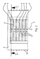
- eine Sicht aus Richtung des Pfeiles II aus Fig. 1.
- In der Zeichnung ist eine Vorrichtung gezeigt, die dazu dient, aus einzelnen, insbesondere kleinteiligen Produkten 1 gebildetes Schüttgut 2 gezielt zu orientieren und weiter zu transportieren, um beispielsweise die einzelnen Produkte 1 des Schüttgutes 2 gezielt in, in der Zeichnung nicht dargestellte, Produktaufnahmen einer Formfolie oder dergl. ablegen zu können. Dazu umfasst die Vorrichtung einen in einem Sortierkasten 3 angeordneten Trichter 4, wobei zur Leistungssteigerung dieser Vorrichtung der Trichter 4 mehrfach vorgesehen ist in einer seriellen Anordnung innerhalb des Sortierkastens 3, wobei jeder Trichter 4 dieser seriellen Anordnung prinzipiell den gleichen, nachfolgend näher zu beschreibenden Aufbau aufweist. Dem bzw. jedem Trichter 4 ist in Transportrichtung eine Zuführrinne 5 nachgeordnet, wobei die Zuführrinne 5 an eine Öffnung 6 im Boden des Sortierkastens 3 angeschlossen ist. Auf zwei gegenüberliegenden Seiten des Trichters 4 sind die Trichterwände aus zwei Lamellen 7 mit geneigt zu der Öffnung 6 verlaufenden Lamellenschultern 8 gebildet, während der Trichter 4 in Umfangsrichtung durch zwei die Lamellen 7 ergänzende Trennwände 9 geschlossen ist. Den Lamellen 7 ist ein Lamellenantrieb 10 zur Verstellung der Lamellen 7 relativ zu der Öffnung 6 zugeordnet, wobei jede Lamelle 7 einen eigenen Lamellenantrieb 10 aufweist.
- Bei dem in der Zeichnung dargstellten Ausführungsbeispiel ist jeder der Lamellen 7 ein verstellbarer, durch eine im Sortierkasten 3 gelagerte Stellschraube gebildeter Anschlag 11 zugeordnet, so dass der Hub der Lamelle 7 zwischen der zur Öffnung 6 vorgestellten und der von der Öffnung 6 zurückgezogenen Richtung variiert und definiert begrenzt werden kann.
- Bei dem in der Zeichnung dargestellten Ausführungsbeispiel ist für den Lamellenantrieb 10 ein durckmittelbetätigter Antrieb vorgesehen und zwar ein Pneumatikantrieb, bei dem der Pneumatikzylinder als Membranzylinder ausgeführt ist. Die Membran des Membranzylinders besteht aus einem lebensmittelrechtlich zugelassen Werkstoff. Weiterhin ist zu beachten, dass dem Lamellenantrieb eine Antriebssteuerung mit einem Frequenzgeber zur variablen Festlegung einer Frequenz der zyklischen Bewegung der Lamelle 7 zugeordnet ist.
- Nachfolgend wird kurz die Betriebsweise der vorstehend beschriebenen Vorrichtung geschildert. Zu Beginn wird das aus einzelnen Produkten 1 gebildete Schüttgut 2 in den Trichter 4 eingefüllt, wobei das Schüttgut 2 auf den beiden sich gegenüberliegenden Lamellenschultern 8 der beiden Lamellen 7 zu liegen kommt. In Abhängigkeit der Größe, der Maße, der Form und/oder der Oberflächenbeschaffenheit der einzelnen Produkte 1 des Schüttgutes 2 wird mittels des Lamellenantiebes 10 den beiden Lamellen 7 eine Bewegung aufgeprägt, die in erster Linie eine translatorische oszillierende Bewegung ist. Dabei bestehen die beiden Möglichkeiten, die beiden Lamellen 7 gleichsinnig oder gegensinnig zu bewegen, wobei bei der gleichsinnigen Bewegung der beiden Lamellen 7 im wesentlichen ein Konus konstanter Gestalt oberhalb der Öffnung verschoben wird, während bei der gegensinnigen Bewegung die durch die Lamellenschultern 8 definierte Größe des Trichters 4 permanent verändert wird. Das Bewegungsmuster der Lamellen 7 kann über die Antriebssteuerung auch verändert werden und insbesondere zur Vermeidung oder Auflösung einer Klumpenbildung in dem Schüttgut 2 ein anderer Hub sowie eine andere Frequenz gewählt werden, wobei zu beachten ist, das prinzipiell auch eine asynchrone Bewegung der beiden sich gegenüberliegenden Lamellen 7 mit dieser Vorrichtung erzeugt werden kann.
Claims (12)
- Vorrichtung zum Orientieren und Weitertransport von Schüttgut (2) aus einem in einem Sortierkasten (3) angeordneten Trichter (4) in eine dem Trichter (4) in Transportrichtung nachgeordnete Zuführrinne (5), dadurch gekennzeichnet, daß die Zuführrinne (5) an eine Öffnung (6) im Boden des Sortierkastens (3) angeschlossen ist und auf zwei gegenüberliegenden Seiten die Trichterwände aus zwei Lamellen (7) mit geneigt zu der Öffnung (6) verlaufenden Lamellenschultern (8) gebildet sind, denen ein Lamellenantrieb (10) zur Verstellung der Lamellen (7) relativ zu der Öffnung (6) zugeordnet ist.
- Vorrichtung nach Anspruch 1, dadurch gekennzeichnet, daß der Trichter (4) in Umfangsrichtung durch zwei die Lamellen (7) ergänzende Trennwände (9) geschlossen ist.
- Vorrichtung nach Anspruch 2, dadurch gekennzeichnet, daß der Trichter (4) mehrfach vorgesehen ist in serieller Anordnung innerhalb des Sortierkastens (3).
- Vorrichtung nach einem der Ansprüche 1 bis 3, dadurch gekennzeichnet, daß jeder Lamelle (7) ein eigener Lamellenantrieb (10) zugeordnet ist zur Bewegungserzeugung unabhängig von der komplementären Lamelle (7).
- Vorrichtung nach einem der Ansprüche 1 bis 4, dadurch gekennzeichnet, daß mindestens einer der Lamellen (7) ein verstellbarer Anschlag (11) zugeordnet ist.
- Vorrichtung nach Anspruch 5, dadurch gekennzeichnet, daß der Anschlag (11) durch eine im Sortierkasten (3) gelagerte Stellschraube gebildet ist.
- Vorrichtung nach einem der Ansprüche 1 bis 6, dadurch gekennzeichnet, daß der Lamellenantrieb (10) als druckmittelbetätigter Antrieb gestaltet ist.
- Vorrichtung nach Anspruch 7, dadurch gekennzeichnet, daß der Lamellenantrieb (10) als Pneumatikantrieb ausgeführt ist.
- Vorrichtung nach Anspruch 8, dadurch gekennzeichnet, daß der Pneumatikzylinder des Pneumatikantriebs als Membranzylinder ausgeführt ist.
- Vorrichtung nach Anspruch 9, dadurch gekennzeichnet, daß die Membran des Membranzylinders aus einem lebensmittelrechtlich zugelassenen Werkstoff besteht.
- Vorrichtung nach einem der Ansprüche 1 bis 10, dadurch gekennzeichnet, daß dem Lamellenantrieb (10) eine Antriebssteuerung mit einem Frequenzgeber zur variablen Festlegung einer Frequenz der zyklischen Bewegung der Lamelle (7) zugeordnet ist.
- Vorrichtung nach einem der Ansprüche 1 bis 11, dadurch gekennzeichnet, daß der Hub der Lamelle (7) einstellbar ist.
Applications Claiming Priority (1)
| Application Number | Priority Date | Filing Date | Title |
|---|---|---|---|
| DE102005018651A DE102005018651A1 (de) | 2005-04-21 | 2005-04-21 | Vorrichtung zum Orientieren und Weitertransport von Schüttgut |
Publications (2)
| Publication Number | Publication Date |
|---|---|
| EP1714873A1 true EP1714873A1 (de) | 2006-10-25 |
| EP1714873B1 EP1714873B1 (de) | 2007-06-06 |
Family
ID=36602748
Family Applications (1)
| Application Number | Title | Priority Date | Filing Date |
|---|---|---|---|
| EP05026544A Expired - Lifetime EP1714873B1 (de) | 2005-04-21 | 2005-12-06 | Vorrichtung zum Orientieren und Weitertransport von Schüttgut |
Country Status (6)
| Country | Link |
|---|---|
| US (1) | US20060237476A1 (de) |
| EP (1) | EP1714873B1 (de) |
| JP (1) | JP2006298492A (de) |
| CN (1) | CN100572225C (de) |
| AT (1) | ATE364010T1 (de) |
| DE (2) | DE102005018651A1 (de) |
Cited By (1)
| Publication number | Priority date | Publication date | Assignee | Title |
|---|---|---|---|---|
| CN115535585A (zh) * | 2022-11-28 | 2022-12-30 | 杭州深度视觉科技有限公司 | 理料装置及设备 |
Families Citing this family (10)
| Publication number | Priority date | Publication date | Assignee | Title |
|---|---|---|---|---|
| RU2586752C2 (ru) * | 2010-12-29 | 2016-06-10 | Филип Моррис Продактс С.А. | Подающее устройство для неориентированных предметов |
| DE102011080746A1 (de) * | 2011-08-10 | 2013-02-14 | Robert Bosch Gmbh | Einrichtung zum Halten und Positionieren von als Tabletten, Hartgelatinekapseln oder ähnlichem ausgebildeten pharmazeutischen Produkten in einer Verpackungsanlage |
| ITMI20120398A1 (it) * | 2012-03-14 | 2013-09-15 | I M A Ind Macchine Automatic He S P A | Gruppo distributore |
| CN102673990B (zh) * | 2012-05-24 | 2015-12-02 | 华嘉利自动机械(昆山)有限公司 | 模块式同方向振动整列机及整列机组 |
| CN103448953B (zh) * | 2013-09-24 | 2016-03-23 | 无锡佳健医疗器械有限公司 | 针灸针包装机的自动下管装置 |
| CN104118718B (zh) * | 2014-06-27 | 2016-05-11 | 浙江科技学院 | 一种可调节圆锥轴承外圈翻面装置 |
| CN105253343B (zh) * | 2015-11-20 | 2017-06-16 | 海瑞恩精密技术(太仓)有限公司 | 一种摆料机 |
| CN105984714B (zh) * | 2016-07-03 | 2018-11-16 | 徐州华阳饲料有限公司 | 一种圆柱形物料给料器的给料方法 |
| CN105984713B (zh) * | 2016-07-03 | 2018-11-16 | 徐州健源有机食品有限公司 | 一种圆柱形物料的给料装置的给料方法 |
| CN106622991B (zh) * | 2016-12-30 | 2020-06-12 | 河南奇测电子科技有限公司 | 柱形工件表面检测流水线、检测方法及姿态调整装置 |
Citations (5)
| Publication number | Priority date | Publication date | Assignee | Title |
|---|---|---|---|---|
| US2828888A (en) * | 1950-01-26 | 1958-04-01 | Nicolle Charles | Apparatus for dispensing fragile articles |
| US6102188A (en) * | 1994-05-18 | 2000-08-15 | Taiyo Yuden Co., Ltd. | Method for supplying chip parts |
| US6357495B1 (en) * | 1998-08-03 | 2002-03-19 | I.M.A. Industria Macchine Automatiche S.P.A. | Device for filling a blister band with products |
| EP1281619A1 (de) * | 2001-08-02 | 2003-02-05 | UHLMANN PAC-SYSTEME GmbH & Co. KG | Vorrichtung zum Sortieren und zum Weitertransport von Schüttgut |
| EP1391386A2 (de) * | 2002-08-21 | 2004-02-25 | Aylward Enterprises, Inc. | Verfahren und Vorrichtung zur Zuführung von Pillen zu einem Behälter |
Family Cites Families (16)
| Publication number | Priority date | Publication date | Assignee | Title |
|---|---|---|---|---|
| US4201313A (en) * | 1978-02-08 | 1980-05-06 | Auto-Place, Inc. | Hopper feeder for singly dispensing short rods or tubes |
| JPS5594946U (de) * | 1979-12-14 | 1980-07-01 | ||
| JPS56161976A (en) * | 1980-05-15 | 1981-12-12 | Matsushita Electric Works Ltd | Method and device for preventing blocking |
| US4469109A (en) * | 1981-12-24 | 1984-09-04 | Creative Research And Manufacturing Inc. | Bone marrow aspiration needle |
| US4828142A (en) * | 1986-01-24 | 1989-05-09 | Eli Lilly & Company | Capsule rectification apparatus |
| SE9300643L (sv) * | 1993-02-26 | 1994-08-27 | Ips Mechatronics Ab | Förfarande och anordning för att mata fram föremål till visst korrekt hanteringsläge |
| US5826696A (en) * | 1994-08-11 | 1998-10-27 | Walter Grassle Gmbh | Apparatus for separating small articles |
| EP0805620B1 (de) * | 1996-05-01 | 2002-02-20 | Pop Man Corporation | Vorrichtung zum Befördern von Chip-Bauteilen |
| TW394496U (en) * | 1996-10-31 | 2000-06-11 | Taiyo Yuden Kk | Chip component feeding apparatus |
| JPH10178297A (ja) * | 1996-12-17 | 1998-06-30 | Taiyo Yuden Co Ltd | 部品供給装置の部品取込機構 |
| JP3579234B2 (ja) * | 1997-12-09 | 2004-10-20 | 太陽誘電株式会社 | チップ部品供給装置 |
| JP3632456B2 (ja) * | 1998-07-06 | 2005-03-23 | 株式会社村田製作所 | 部品供給装置 |
| JP2001026316A (ja) * | 1999-05-12 | 2001-01-30 | Fuji Mach Mfg Co Ltd | 整列供給装置 |
| JP3328738B2 (ja) * | 1999-06-16 | 2002-09-30 | 株式会社不二鉄工所 | ロール搬送装置 |
| JP3520008B2 (ja) * | 1999-12-24 | 2004-04-19 | 太陽誘電株式会社 | 電子部品供給装置 |
| US6884016B2 (en) * | 2002-11-04 | 2005-04-26 | Kimberly-Clark Worldwide, Inc. | Positioning system for an automatic accumulation system |
-
2005
- 2005-04-21 DE DE102005018651A patent/DE102005018651A1/de not_active Withdrawn
- 2005-12-06 EP EP05026544A patent/EP1714873B1/de not_active Expired - Lifetime
- 2005-12-06 DE DE502005000830T patent/DE502005000830D1/de not_active Expired - Lifetime
- 2005-12-06 AT AT05026544T patent/ATE364010T1/de not_active IP Right Cessation
-
2006
- 2006-04-19 US US11/407,407 patent/US20060237476A1/en not_active Abandoned
- 2006-04-20 JP JP2006117293A patent/JP2006298492A/ja not_active Ceased
- 2006-04-21 CN CNB2006100746309A patent/CN100572225C/zh not_active Expired - Fee Related
Patent Citations (5)
| Publication number | Priority date | Publication date | Assignee | Title |
|---|---|---|---|---|
| US2828888A (en) * | 1950-01-26 | 1958-04-01 | Nicolle Charles | Apparatus for dispensing fragile articles |
| US6102188A (en) * | 1994-05-18 | 2000-08-15 | Taiyo Yuden Co., Ltd. | Method for supplying chip parts |
| US6357495B1 (en) * | 1998-08-03 | 2002-03-19 | I.M.A. Industria Macchine Automatiche S.P.A. | Device for filling a blister band with products |
| EP1281619A1 (de) * | 2001-08-02 | 2003-02-05 | UHLMANN PAC-SYSTEME GmbH & Co. KG | Vorrichtung zum Sortieren und zum Weitertransport von Schüttgut |
| EP1391386A2 (de) * | 2002-08-21 | 2004-02-25 | Aylward Enterprises, Inc. | Verfahren und Vorrichtung zur Zuführung von Pillen zu einem Behälter |
Cited By (1)
| Publication number | Priority date | Publication date | Assignee | Title |
|---|---|---|---|---|
| CN115535585A (zh) * | 2022-11-28 | 2022-12-30 | 杭州深度视觉科技有限公司 | 理料装置及设备 |
Also Published As
| Publication number | Publication date |
|---|---|
| EP1714873B1 (de) | 2007-06-06 |
| CN1850562A (zh) | 2006-10-25 |
| US20060237476A1 (en) | 2006-10-26 |
| JP2006298492A (ja) | 2006-11-02 |
| DE502005000830D1 (de) | 2007-07-19 |
| DE102005018651A1 (de) | 2006-10-26 |
| ATE364010T1 (de) | 2007-06-15 |
| CN100572225C (zh) | 2009-12-23 |
Similar Documents
| Publication | Publication Date | Title |
|---|---|---|
| EP1714873B1 (de) | Vorrichtung zum Orientieren und Weitertransport von Schüttgut | |
| DE102013111828B4 (de) | Ablängvorrichtung für eine Pelletpresse, Pelletpresse mit einer solchenAblängvorrichtung für biogene faserhaltige Pellets, Verfahren zurHerstellung von biogenen faserhaltigen Pellets sowie Verwendung ei-ner Pelletpresse | |
| DE102009023729A1 (de) | Vorrichtung und Verfahren zum Aufschneiden von Lebensmittelprodukten | |
| DE102011013919A1 (de) | Schneidmaschine | |
| DE2158704A1 (de) | Flugkolbenvibrator | |
| EP2463032A2 (de) | Vorrichtung und Verfahren zum Sieben | |
| DE202010006744U1 (de) | Sortiermaschine zum schonenden Sortieren stoßgefährdeter Knollengewächse nach bestimmten Größenmaßen | |
| EP3284564A1 (de) | Hobel für lebensmittel | |
| CH706283A2 (de) | Siebmaschine zum Klassieren oder Aufbereiten von Kies, Sand oder dergleichen. | |
| DE102016108200B3 (de) | Separator zum Trennen von miteinander vermischten Stoffen unterschiedlicher Fließfähigkeit | |
| EP3192755A1 (de) | Fördervorrrichtung mit förderstrombegrenzer | |
| DE202013003438U1 (de) | Vorrichtung zum Schneiden von Lebensmitteln, insbesondere Hochleistungs-Slicer | |
| DE4017652A1 (de) | Vorrichtung zum sieben von haus- und/oder industriemuell | |
| EP4400792A1 (de) | Vorrichtung zum trocknen und/oder kühlen von schüttgut | |
| EP0879358B1 (de) | Rotationskolbendosierer | |
| EP4275796A1 (de) | Vorrichtung zum zerkleinern von streifenförmigem material und verfahren zu deren betrieb | |
| DE102012005598A1 (de) | Vorrichtung zum Fördern von Produkten | |
| DE102008013806B4 (de) | Portioniervorrichtung (Aufwärts Schneiden) | |
| DE4421711C2 (de) | Vorrichtung zum Zerkleinern von organischen Massen | |
| EP0984710B1 (de) | Abteiler, insbesondere zur separierung von besatzmaterial zur herstellung von bürsten, wie z.b. streifenbürsten | |
| EP0745462B1 (de) | Vorrichtung zum Ablängen oder Schlitzen von kontinuierlich bewegtem, strangförmigem Material | |
| US6357681B1 (en) | Spring cutter-separator | |
| DE102011117418A1 (de) | Labyrinthmühle | |
| DE102007050001A1 (de) | Vibrationsgleitfördereinheit und Vibrationsgleitförderer | |
| DE102010055785A1 (de) | Konti Kutter Vakuum |
Legal Events
| Date | Code | Title | Description |
|---|---|---|---|
| PUAI | Public reference made under article 153(3) epc to a published international application that has entered the european phase |
Free format text: ORIGINAL CODE: 0009012 |
|
| 17P | Request for examination filed |
Effective date: 20060729 |
|
| AK | Designated contracting states |
Kind code of ref document: A1 Designated state(s): AT BE BG CH CY CZ DE DK EE ES FI FR GB GR HU IE IS IT LI LT LU LV MC NL PL PT RO SE SI SK TR |
|
| AX | Request for extension of the european patent |
Extension state: AL BA HR MK YU |
|
| GRAP | Despatch of communication of intention to grant a patent |
Free format text: ORIGINAL CODE: EPIDOSNIGR1 |
|
| GRAS | Grant fee paid |
Free format text: ORIGINAL CODE: EPIDOSNIGR3 |
|
| GRAA | (expected) grant |
Free format text: ORIGINAL CODE: 0009210 |
|
| AK | Designated contracting states |
Kind code of ref document: B1 Designated state(s): AT BE BG CH CY CZ DE DK EE ES FI FR GB GR HU IE IS IT LI LT LU LV MC NL PL PT RO SE SI SK TR |
|
| PG25 | Lapsed in a contracting state [announced via postgrant information from national office to epo] |
Ref country code: FI Free format text: LAPSE BECAUSE OF FAILURE TO SUBMIT A TRANSLATION OF THE DESCRIPTION OR TO PAY THE FEE WITHIN THE PRESCRIBED TIME-LIMIT Effective date: 20070606 |
|
| REG | Reference to a national code |
Ref country code: GB Ref legal event code: FG4D Free format text: NOT ENGLISH |
|
| REG | Reference to a national code |
Ref country code: CH Ref legal event code: NV Representative=s name: ISLER & PEDRAZZINI AG Ref country code: CH Ref legal event code: EP |
|
| AKX | Designation fees paid |
Designated state(s): AT BE BG CH CY CZ DE DK EE ES FI FR GB GR HU IE IS IT LI LT LU LV MC NL PL PT RO SE SI SK TR |
|
| REG | Reference to a national code |
Ref country code: IE Ref legal event code: FG4D Free format text: LANGUAGE OF EP DOCUMENT: GERMAN |
|
| REF | Corresponds to: |
Ref document number: 502005000830 Country of ref document: DE Date of ref document: 20070719 Kind code of ref document: P |
|
| PG25 | Lapsed in a contracting state [announced via postgrant information from national office to epo] |
Ref country code: SE Free format text: LAPSE BECAUSE OF FAILURE TO SUBMIT A TRANSLATION OF THE DESCRIPTION OR TO PAY THE FEE WITHIN THE PRESCRIBED TIME-LIMIT Effective date: 20070906 |
|
| GBT | Gb: translation of ep patent filed (gb section 77(6)(a)/1977) |
Effective date: 20070822 |
|
| PG25 | Lapsed in a contracting state [announced via postgrant information from national office to epo] |
Ref country code: ES Free format text: LAPSE BECAUSE OF FAILURE TO SUBMIT A TRANSLATION OF THE DESCRIPTION OR TO PAY THE FEE WITHIN THE PRESCRIBED TIME-LIMIT Effective date: 20070917 |
|
| REG | Reference to a national code |
Ref country code: CH Ref legal event code: PCAR Free format text: ISLER & PEDRAZZINI AG;POSTFACH 1772;8027 ZUERICH (CH) |
|
| PG25 | Lapsed in a contracting state [announced via postgrant information from national office to epo] |
Ref country code: PL Free format text: LAPSE BECAUSE OF FAILURE TO SUBMIT A TRANSLATION OF THE DESCRIPTION OR TO PAY THE FEE WITHIN THE PRESCRIBED TIME-LIMIT Effective date: 20070606 |
|
| NLV1 | Nl: lapsed or annulled due to failure to fulfill the requirements of art. 29p and 29m of the patents act | ||
| REG | Reference to a national code |
Ref country code: IE Ref legal event code: FD4D |
|
| PG25 | Lapsed in a contracting state [announced via postgrant information from national office to epo] |
Ref country code: CZ Free format text: LAPSE BECAUSE OF FAILURE TO SUBMIT A TRANSLATION OF THE DESCRIPTION OR TO PAY THE FEE WITHIN THE PRESCRIBED TIME-LIMIT Effective date: 20070606 Ref country code: SI Free format text: LAPSE BECAUSE OF FAILURE TO SUBMIT A TRANSLATION OF THE DESCRIPTION OR TO PAY THE FEE WITHIN THE PRESCRIBED TIME-LIMIT Effective date: 20070606 Ref country code: PT Free format text: LAPSE BECAUSE OF FAILURE TO SUBMIT A TRANSLATION OF THE DESCRIPTION OR TO PAY THE FEE WITHIN THE PRESCRIBED TIME-LIMIT Effective date: 20071106 Ref country code: IE Free format text: LAPSE BECAUSE OF FAILURE TO SUBMIT A TRANSLATION OF THE DESCRIPTION OR TO PAY THE FEE WITHIN THE PRESCRIBED TIME-LIMIT Effective date: 20070606 Ref country code: NL Free format text: LAPSE BECAUSE OF FAILURE TO SUBMIT A TRANSLATION OF THE DESCRIPTION OR TO PAY THE FEE WITHIN THE PRESCRIBED TIME-LIMIT Effective date: 20070606 Ref country code: IS Free format text: LAPSE BECAUSE OF FAILURE TO SUBMIT A TRANSLATION OF THE DESCRIPTION OR TO PAY THE FEE WITHIN THE PRESCRIBED TIME-LIMIT Effective date: 20071006 Ref country code: BG Free format text: LAPSE BECAUSE OF FAILURE TO SUBMIT A TRANSLATION OF THE DESCRIPTION OR TO PAY THE FEE WITHIN THE PRESCRIBED TIME-LIMIT Effective date: 20070906 |
|
| EN | Fr: translation not filed | ||
| PG25 | Lapsed in a contracting state [announced via postgrant information from national office to epo] |
Ref country code: LT Free format text: LAPSE BECAUSE OF FAILURE TO SUBMIT A TRANSLATION OF THE DESCRIPTION OR TO PAY THE FEE WITHIN THE PRESCRIBED TIME-LIMIT Effective date: 20070606 Ref country code: LV Free format text: LAPSE BECAUSE OF FAILURE TO SUBMIT A TRANSLATION OF THE DESCRIPTION OR TO PAY THE FEE WITHIN THE PRESCRIBED TIME-LIMIT Effective date: 20070606 Ref country code: SK Free format text: LAPSE BECAUSE OF FAILURE TO SUBMIT A TRANSLATION OF THE DESCRIPTION OR TO PAY THE FEE WITHIN THE PRESCRIBED TIME-LIMIT Effective date: 20070606 |
|
| PLBE | No opposition filed within time limit |
Free format text: ORIGINAL CODE: 0009261 |
|
| STAA | Information on the status of an ep patent application or granted ep patent |
Free format text: STATUS: NO OPPOSITION FILED WITHIN TIME LIMIT |
|
| PG25 | Lapsed in a contracting state [announced via postgrant information from national office to epo] |
Ref country code: DK Free format text: LAPSE BECAUSE OF FAILURE TO SUBMIT A TRANSLATION OF THE DESCRIPTION OR TO PAY THE FEE WITHIN THE PRESCRIBED TIME-LIMIT Effective date: 20070606 Ref country code: GR Free format text: LAPSE BECAUSE OF FAILURE TO SUBMIT A TRANSLATION OF THE DESCRIPTION OR TO PAY THE FEE WITHIN THE PRESCRIBED TIME-LIMIT Effective date: 20070907 |
|
| 26N | No opposition filed |
Effective date: 20080307 |
|
| PG25 | Lapsed in a contracting state [announced via postgrant information from national office to epo] |
Ref country code: RO Free format text: LAPSE BECAUSE OF FAILURE TO SUBMIT A TRANSLATION OF THE DESCRIPTION OR TO PAY THE FEE WITHIN THE PRESCRIBED TIME-LIMIT Effective date: 20070606 |
|
| BERE | Be: lapsed |
Owner name: UHLMANN PAC-SYSTEME G.M.B.H. & CO. KG Effective date: 20071231 |
|
| PG25 | Lapsed in a contracting state [announced via postgrant information from national office to epo] |
Ref country code: FR Free format text: LAPSE BECAUSE OF FAILURE TO SUBMIT A TRANSLATION OF THE DESCRIPTION OR TO PAY THE FEE WITHIN THE PRESCRIBED TIME-LIMIT Effective date: 20080201 Ref country code: MC Free format text: LAPSE BECAUSE OF NON-PAYMENT OF DUE FEES Effective date: 20071231 |
|
| PG25 | Lapsed in a contracting state [announced via postgrant information from national office to epo] |
Ref country code: BE Free format text: LAPSE BECAUSE OF NON-PAYMENT OF DUE FEES Effective date: 20071231 |
|
| PG25 | Lapsed in a contracting state [announced via postgrant information from national office to epo] |
Ref country code: EE Free format text: LAPSE BECAUSE OF FAILURE TO SUBMIT A TRANSLATION OF THE DESCRIPTION OR TO PAY THE FEE WITHIN THE PRESCRIBED TIME-LIMIT Effective date: 20070606 |
|
| PG25 | Lapsed in a contracting state [announced via postgrant information from national office to epo] |
Ref country code: AT Free format text: LAPSE BECAUSE OF NON-PAYMENT OF DUE FEES Effective date: 20071206 |
|
| PG25 | Lapsed in a contracting state [announced via postgrant information from national office to epo] |
Ref country code: CY Free format text: LAPSE BECAUSE OF FAILURE TO SUBMIT A TRANSLATION OF THE DESCRIPTION OR TO PAY THE FEE WITHIN THE PRESCRIBED TIME-LIMIT Effective date: 20070606 |
|
| PG25 | Lapsed in a contracting state [announced via postgrant information from national office to epo] |
Ref country code: LU Free format text: LAPSE BECAUSE OF NON-PAYMENT OF DUE FEES Effective date: 20071206 |
|
| PG25 | Lapsed in a contracting state [announced via postgrant information from national office to epo] |
Ref country code: HU Free format text: LAPSE BECAUSE OF FAILURE TO SUBMIT A TRANSLATION OF THE DESCRIPTION OR TO PAY THE FEE WITHIN THE PRESCRIBED TIME-LIMIT Effective date: 20071207 Ref country code: TR Free format text: LAPSE BECAUSE OF FAILURE TO SUBMIT A TRANSLATION OF THE DESCRIPTION OR TO PAY THE FEE WITHIN THE PRESCRIBED TIME-LIMIT Effective date: 20070606 |
|
| PGFP | Annual fee paid to national office [announced via postgrant information from national office to epo] |
Ref country code: CH Payment date: 20091224 Year of fee payment: 5 |
|
| PGFP | Annual fee paid to national office [announced via postgrant information from national office to epo] |
Ref country code: GB Payment date: 20091231 Year of fee payment: 5 Ref country code: IT Payment date: 20091217 Year of fee payment: 5 |
|
| PGFP | Annual fee paid to national office [announced via postgrant information from national office to epo] |
Ref country code: DE Payment date: 20091228 Year of fee payment: 5 |
|
| REG | Reference to a national code |
Ref country code: CH Ref legal event code: PL |
|
| GBPC | Gb: european patent ceased through non-payment of renewal fee |
Effective date: 20101206 |
|
| PG25 | Lapsed in a contracting state [announced via postgrant information from national office to epo] |
Ref country code: CH Free format text: LAPSE BECAUSE OF NON-PAYMENT OF DUE FEES Effective date: 20101231 Ref country code: LI Free format text: LAPSE BECAUSE OF NON-PAYMENT OF DUE FEES Effective date: 20101231 |
|
| REG | Reference to a national code |
Ref country code: DE Ref legal event code: R119 Ref document number: 502005000830 Country of ref document: DE Effective date: 20110701 |
|
| PG25 | Lapsed in a contracting state [announced via postgrant information from national office to epo] |
Ref country code: DE Free format text: LAPSE BECAUSE OF NON-PAYMENT OF DUE FEES Effective date: 20110701 Ref country code: GB Free format text: LAPSE BECAUSE OF NON-PAYMENT OF DUE FEES Effective date: 20101206 |
|
| PG25 | Lapsed in a contracting state [announced via postgrant information from national office to epo] |
Ref country code: IT Free format text: LAPSE BECAUSE OF NON-PAYMENT OF DUE FEES Effective date: 20101206 |