EP1714897A1 - Dosenförmiger Behälter zur Aufnahme von entgasendem Füllgut - Google Patents
Dosenförmiger Behälter zur Aufnahme von entgasendem Füllgut Download PDFInfo
- Publication number
- EP1714897A1 EP1714897A1 EP06007012A EP06007012A EP1714897A1 EP 1714897 A1 EP1714897 A1 EP 1714897A1 EP 06007012 A EP06007012 A EP 06007012A EP 06007012 A EP06007012 A EP 06007012A EP 1714897 A1 EP1714897 A1 EP 1714897A1
- Authority
- EP
- European Patent Office
- Prior art keywords
- degassing
- gas
- container
- side membrane
- tight
- Prior art date
- Legal status (The legal status is an assumption and is not a legal conclusion. Google has not performed a legal analysis and makes no representation as to the accuracy of the status listed.)
- Granted
Links
Images

Classifications
-
- B—PERFORMING OPERATIONS; TRANSPORTING
- B65—CONVEYING; PACKING; STORING; HANDLING THIN OR FILAMENTARY MATERIAL
- B65D—CONTAINERS FOR STORAGE OR TRANSPORT OF ARTICLES OR MATERIALS, e.g. BAGS, BARRELS, BOTTLES, BOXES, CANS, CARTONS, CRATES, DRUMS, JARS, TANKS, HOPPERS, FORWARDING CONTAINERS; ACCESSORIES, CLOSURES, OR FITTINGS THEREFOR; PACKAGING ELEMENTS; PACKAGES
- B65D51/00—Closures not otherwise provided for
- B65D51/18—Arrangements of closures with protective outer cap-like covers or of two or more co-operating closures
- B65D51/20—Caps, lids, or covers co-operating with an inner closure arranged to be opened by piercing, cutting, or tearing
-
- B—PERFORMING OPERATIONS; TRANSPORTING
- B65—CONVEYING; PACKING; STORING; HANDLING THIN OR FILAMENTARY MATERIAL
- B65D—CONTAINERS FOR STORAGE OR TRANSPORT OF ARTICLES OR MATERIALS, e.g. BAGS, BARRELS, BOTTLES, BOXES, CANS, CARTONS, CRATES, DRUMS, JARS, TANKS, HOPPERS, FORWARDING CONTAINERS; ACCESSORIES, CLOSURES, OR FITTINGS THEREFOR; PACKAGING ELEMENTS; PACKAGES
- B65D51/00—Closures not otherwise provided for
- B65D51/16—Closures not otherwise provided for with means for venting air or gas
- B65D51/1633—Closures not otherwise provided for with means for venting air or gas whereby venting occurs by automatic opening of the closure, container or other element
- B65D51/1644—Closures not otherwise provided for with means for venting air or gas whereby venting occurs by automatic opening of the closure, container or other element the element being a valve
- B65D51/165—Closures not otherwise provided for with means for venting air or gas whereby venting occurs by automatic opening of the closure, container or other element the element being a valve formed by a slit or narrow opening
-
- B—PERFORMING OPERATIONS; TRANSPORTING
- B65—CONVEYING; PACKING; STORING; HANDLING THIN OR FILAMENTARY MATERIAL
- B65D—CONTAINERS FOR STORAGE OR TRANSPORT OF ARTICLES OR MATERIALS, e.g. BAGS, BARRELS, BOTTLES, BOXES, CANS, CARTONS, CRATES, DRUMS, JARS, TANKS, HOPPERS, FORWARDING CONTAINERS; ACCESSORIES, CLOSURES, OR FITTINGS THEREFOR; PACKAGING ELEMENTS; PACKAGES
- B65D2251/00—Details relating to container closures
- B65D2251/0003—Two or more closures
- B65D2251/0006—Upper closure
- B65D2251/0018—Upper closure of the 43-type
-
- B—PERFORMING OPERATIONS; TRANSPORTING
- B65—CONVEYING; PACKING; STORING; HANDLING THIN OR FILAMENTARY MATERIAL
- B65D—CONTAINERS FOR STORAGE OR TRANSPORT OF ARTICLES OR MATERIALS, e.g. BAGS, BARRELS, BOTTLES, BOXES, CANS, CARTONS, CRATES, DRUMS, JARS, TANKS, HOPPERS, FORWARDING CONTAINERS; ACCESSORIES, CLOSURES, OR FITTINGS THEREFOR; PACKAGING ELEMENTS; PACKAGES
- B65D2251/00—Details relating to container closures
- B65D2251/0003—Two or more closures
- B65D2251/0068—Lower closure
- B65D2251/0093—Membrane
Definitions
- the invention relates to a can-shaped container for receiving degassed filling material, consisting of a hull of cardboard or paper composite material with a gas-tight coating, a gas-tight at one end face arranged bottom, one on a formed on the opposite end of the fuselage outer flange, a resting on this Closure over which can escape to the outside in order to avoid excessive pressure in the container gas, and a latching on the outer crimp of the fuselage attached slip-on lid without gas-tight function, being arranged between the lid and the closure cams to ensure degassing.
- liquid cleaning agents DE 92 17 614 U1
- the closure element consists of a gas-permeable material. It is bordered on the peripheral edge between the protective insert and the underside of the lid and is intended to seal the space between the protective insert and the closure element with its voltage applied to the inside of the lid peripheral edge.
- the slip lid engages over the sealing edge of the closure element and also seals the gap between it and the protective insert.
- the slip-on lid is provided with vent holes on its cover surface and with spacer rings on its underside, which bulge the membrane-like closure element downwards and keep it away from the ventilation holes. Since the membrane-like closure element should consist inter alia of an open-pore material, a gas exchange in both directions, so also an access of ambient air into the container is possible. This is undesirable in food and beverages, as they lose their aroma or their durability is impaired when air enters. Examples include the coffee or espresso tabs commonly used today, such as those used for brewing in coffee or espresso machines, or also mentioned ready-made dough preparations.
- the invention is based on the object, in a can-shaped container with the features of the preamble of claim 1 ( US 3,589,545 ) to propose an education that allows in particular the flavor of the degassed contents and its durability not affecting accommodation of the contents in the container.
- the closure has two peripherally gas-tight interconnected membranes, of which the container-side membrane is sealed gas-tight on the outer flanges that both membranes each have at least one narrow vent slot, which are offset from each other and between those in the space between the membranes a film-like oil barrier in the region of the degassing slot of the container-side membrane is arranged, and that the cover-side membrane at a distance to the inside of the slip lid holding cam are formed on the inside of the lid.
- the construction of the degassing valve ensures that the container, which is always under slight overpressure, is not ventilated from the outside, which is essential for maintaining the aroma and the flavorings in the product, e.g. Coffee, espresso tabs or the like, and the shelf life of the contents is important.
- the cams are arranged and / or shaped so that they do not lay the degassing slot (s) in the cover-side membrane in any rotational position of the slip-on lid. This ensures that the or the degassing slot (s) always completely, but at least partially be exposed and the degassing products can flow into the space between the membrane and slip lid.
- the cams are formed by a plurality of radial ribs, the ribs starting at a distance from the edge of the slip lid and from the inside of the fuselage.
- the slip lid lies with its underside in the region of its periphery on the cover-side membrane, which is sealed together with the container-side membrane on the outer flange of the fuselage, while in the more inner region, the closure membranes are formed by the ribs slightly downwards. There, the degassing spaces between the ribs and the closure membrane are formed.
- the ribs also set at a distance from the center of the slip lid to limit the deformation of the membrane to a minimum necessary area.
- the ribs are advantageously rounded so as not to exert any shear forces on the sealing membrane.
- Fig. 1 reproduced in section can-shaped container has a hull 1 made of a cardboard or paper composite material, which is gas-tightly coated on the inside and / or outside.
- the hull 1 is formed on its front side to form a facedbördel 2.
- a fuselage 1 cross-outer flange of a bottom is gas-tightly sealed (not shown).
- the container is finally closed by a Stülpdeckel 5, the outer rim 2 removably overlaps with its peripheral edge and locked with an annular bead 6 or with part-annular ribs behind the Au- touchbördel 2.
- a closure for the product serves a membrane composite of a cover-side membrane 3 and a sealed on the bottom in the peripheral region 8 container-side membrane 7.
- the membrane 7 is gas-tight together with the membrane 3 in the outer region 4 on the outer flange 2 of the hull 1 of the container sealed.
- the membrane 3 has at least one narrow degassing slot 9 and the membrane 7 has a narrow degassing slot 10, which communicates via a narrow space gap 11 between the two diaphragms.
- the cover-side membrane 3 preferably has a further degassing slot, not shown in FIG. 1, which is arranged in correspondence with the degassing slot 9 on the other side of the container, not shown.
- a film-like oil barrier 13 is arranged in the region of the degassing slot 10 of the container-side membrane 7, through which gas can pass only at a certain overpressure.
- cam 12 in the form of narrow radial ribs are formed on the underside of the slip lid 5, which hold the cover-side membrane 3 at a distance from the underside of the slip lid 5 (see Fig. 1).
- the ribs 12 set at a distance from both the peripheral edge and the center of the slip lid 4, as shown in FIG. 2 can be seen.
- the ribs 12, which otherwise have only a very small height and width, are rounded, as can be seen from FIG.
- Degassing constituents of the filling material for example CO 2 in the case of coffee or espresso tablets, or blowing agent in the case of finished dough preparations can via the degassing slot 10, the film-like oil barrier 13, the gap 11 between the two membranes 3 and 7 and the degassing slot. 9 in the escape between the ribs on the one hand and the underside of the slip lid 5 and the top of the closure membrane 3 on the other hand escape. If the pressure continues to rise, the degassing products can also flow outward over a gap between the outer edge of the slip lid 5 and the peripheral edge of the cover-side membrane.
Landscapes
- Engineering & Computer Science (AREA)
- Mechanical Engineering (AREA)
- Packages (AREA)
- Closures For Containers (AREA)
- Filling Or Discharging Of Gas Storage Vessels (AREA)
Abstract
Description
- Die Erfindung betrifft einen dosenförmigen Behälter zur Aufnahme von entgasendem Füllgut, bestehend aus einem Rumpf aus Karton- oder Papierverbundmaterial mit einer gasdichten Beschichtung, einem an dessen einer Stirnseite gasdicht angeordneten Boden, einer auf einem an der gegenüberliegenden Stirnseite des Rumpfs ausgebildeten Außenbördel, einem diesem aufliegenden Verschluss über den zur Vermeidung eines zu großen Überdrucks in dem Behälter Gas nach außen entweichen kann, und einem auf den Außenbördel des Rumpfs rastend aufgesetzten Stülpdeckel ohne Gasdichtfunktion, wobei zwischen dem Deckel und dem Verschluss Nocken zur Gewährleistung der Entgasung angeordnet sind.
- Bei einem bekannten Behälter zur Aufnahme von entgasenden, flüssigen Reinigungsmitteln (
DE 92 17 614 U1 ) ist in den Stülpdeckel ein nach innen durchgewölbter Schutzeinsatz mit Entgasungsöffnungen eingesetzt, über die das unter Überdruck stehende Gas in einen Raum zwischen dem Schutzeinsatz und einem darüber angeordneten, membranartigen Verschlusselement übertreten kann. Das Verschlusselement besteht aus einem gasdurchlässigen Material. Es ist am Umfangsrand zwischen dem Schutzeinsatz und der Unterseite des Deckels eingefasst und soll den Raum zwischen dem Schutzeinsatz und dem Verschlusselement mit seinem an der Deckelinnenseite anliegenden Umfangsrand abdichten. Der Stülpdeckel übergreift den Dichtrand des Verschlusselementes und dichtet ferner den Spalt zwischen ihm und dem Schutzeinsatz ab. Der Stülpdeckel ist an seiner Deckelfläche mit Entlüftungsbohrungen und an seiner Unterseite mit Abstandsringen versehen, die das membranartige Verschlusselement nach unten ausbeulen und von den Entlüftungsbohrungen fernhalten. Da das membranartige Verschlusselement unter anderem aus einem offenporigen Material bestehen soll, ist ein Gasaustausch in beiden Richtungen, also auch ein Zutritt von Umgebungsluft in den Behälter möglich. Dies ist bei Lebens- und Genussmitteln unerwünscht, da sie bei Luftzutritt ihr Aroma verlieren oder ihre Haltbarkeit beeinträchtigt wird. Als Beispiele hierfür seien die heute gebräuchlichen Kaffee- oder Espresso-Tabs, wie sie zum Aufbrühen in Kaffee- oder Espressomaschinen verwendet werden, oder auch Fertigteigzubereitungen erwähnt. - Bei einem anderen bekannten Behälter (
US 3 589 545 ) ist zwischen dem nach innen eingebogenen Rand des Behälterhalses und einem auf dessen Außenseite aufgeschraubten Deckel ein membranartiger Verschluss angeordnet, der mit seinem Rand auf einem Teil des Umfangs lose aufliegt. Der membranartige Verschluss weist nach oben reichende Nocken auf, mit dem er sich an der Unterseite der Deckelfläche des Schraubdeckels abstützt. Ferner ist der Deckel mit Entgasungsbohrungen versehen. Bei Ausbildung eines Überdrucks in dem Behälter hebt sich der membranartige Verschluss am Umfangsrand vom Deckelflansch ab und kann das Gas zwischen ihm und dem Deckelflansch entweichen und über die Entgasungsöffnungen austreten. Bei diesem Aufbau ist eine wirksame Abdichtung zwischen dem Behälterflansch und dem ihm teilweise lose aufliegenden Umfangsrand des membranartigen Verschlusses nicht gewährleistet. Für empfindliche Füllgüter, wie die zuvor genannten Produkte, gelten gleichfalls die zuvor genannten Nachteile. - Es ist schließlich bei einem Behälter bekannt (
DE 297 12 611 ), eine Verschlussmembran auf den Außenbördel gasdicht aufzusiegeln. Hierbei ist keine Entgasungsmöglichkeit gegeben. - Der Erfindung liegt die Aufgabe zugrunde, bei einem dosenförmigen Behälter mit den Merkmalen des Oberbegriffs des Anspruchs 1 (
US 3 589 545 ) eine Ausbildung vorzuschlagen, die insbesondere eine das Aroma des entgasenden Füllgutes und dessen Haltbarkeit nicht beeinträchtigende Unterbringung des Füllgutes in dem Behälter ermöglicht. - Diese Aufgabe wird erfindungsgemäß dadurch gelöst, dass der Verschluss zwei umfangsseitig gasdicht miteinander verbundene Membranen aufweist, von denen die behälterseitige Membran auf den Außenbördel gasdicht aufgesiegelt ist, dass beide Membranen wenigstens je einen schmalen Entgasungsschlitz aufweisen, die gegeneinander versetzt sind und zwischen denen im Zwischenraum zwischen den Membranen eine filmartige Ölbarriere im Bereich des Entgasungsschlitzes der behälterseitigen Membran angeordnet ist, und dass die die deckelseitige Membran auf Abstand zur Innenseite des Stülpdeckels haltenden Nocken an der Innenseite des Deckels aufgeformt sind.
- Durch die beiden schmalen Entgasungsschlitze in den beiden Membranen in Verbindung mit der im Bereich des Entgasungsschlitzes der behälterseitigen Membran angeordneten Ölbarriere, die den schmalen Zwischenraumspalt zwischen den beiden Membranen teilweise ausfüllt, wird eine Art Ventil geschaffen, das nur auf Gasdruck, also insbesondere auf einen sich durch die Entgasung des Füllguts aufbauenden Überdruck im Behälter anspricht.
- Durch die Nocken auf der Unterseite des Stülpdeckels werden zwischen diesem und der darunter liegenden deckelseitigen Membran Entgasungsräume geschaffen und aufrechterhalten, in die das aus dem Füllgut austretende Gas nach Durchdringen des Entgasungsschlitzes in der behälterseitigen Membran, des Zwischenraums zwischen dieser und der deckelseitigen Membran und des Entgasungsschlitzes in letzterer überströmen kann. Da der Stülpdeckel lösbar auf den Außenbördel des Rumpfs aufgesetzt ist und im Bereich der Auflage auf dem Umfangsrand der Verschlussmembran kein dichter Verschluss gegeben ist, kann das sich in den Entgasungsräumen unterhalb der Unterseite des Stülpdeckels sammelnde Gas auch nach außen über den Rand des Stülpdeckels entweichen. Gesonderter Entlüftungsöffnungen im Deckel bedarf es hierzu nicht.
- Durch den Aufbau des Entgasungsventils ist gewährleistet, dass der stets unter leichtem Überdruck stehende Behälter nicht von außen belüftet wird, was für den Erhalt des Aromas und der Geschmacksstoffe im Füllgut, z.B. Kaffee-, Espresso-Tabs oder dergleichen, und die Haltbarkeit des Füllgutes von Bedeutung ist.
- Vorteilhafterweise sind die Nocken so angeordnet und/oder geformt, dass sie in keiner Drehlage des Stülpdeckels den bzw. die Entgasungsschlitz(e) in der deckelseitigen Membran verlegen. Damit ist sichergestellt, dass der bzw. die Entgasungsschlitz(e) stets vollständig, zumindest aber teilweise freiliegen und die Entgasungsprodukte in den Raum zwischen Membran und Stülpdeckel überströmen können.
- Vorzugsweise sind die Nocken von einer Mehrzahl radialer Rippen gebildet, wobei die Rippen mit Abstand vom Rand des Stülpdeckels und von der Innenseite des Rumpfs ansetzen.
- Der Stülpdeckel liegt mit seiner Unterseite im Bereich seiner Peripherie auf der deckelseitigen Membran, die zusammen mit der behälterseitigen Membran auf den Aussenbördel des Rumpfs aufgesiegelt ist, auf, während im weiter innen liegenden Bereich die Verschlussmembranen durch die Rippen etwas nach unten ausgeformt werden. Dort werden die Entgasungsräume zwischen den Rippen und der Verschlussmembran gebildet.
- Zweckmäßigerweise setzen die Rippen auch mit Abstand vom Zentrum des Stülpdeckels an, um die Verformung der Membran auf eine minimal notwendige Fläche zu beschränken.
- Schließlich sind die Rippen mit Vorteil verrundet, um an der Verschlussmembran keine Scherkräfte zur Wirkung zu bringen.
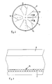
- Nachstehend ist die Erfindung anhand eines in der Zeichnung wiedergegebenen Ausführungsbeispiels beschrieben. In der Zeichnung zeigen:
- Fig. 1
- einen stark vergrößerten Teilschnitt einer Ausführungsform des dosenförmigen Behälters im bereich des Verschlusses;
- Fig. 2
- eine maßstabsgerechte Draufsicht auf die Unterseite des Stülpdeckels und
- Fig. 3
- einen stark vergrößerten Teilschnitt III-III gemäß Fig. 2.
- Der in Fig. 1 ausschnittsweise im Schnitt wiedergegebene dosenförmige Behälter weist einen Rumpf 1 aus einem Karton- oder Papierverbundmaterial auf, der innen- und/oder außenseitig gasdicht beschichtet ist. Der Rumpf 1 ist an seiner Stirnseite zu einem Außenbördel 2 umgeformt. An der gegenüberliegenden Stirnseite ist der Behälter durch einen den Rumpf 1 übergreifenden Außenbördel eines Bodens gasdicht verschlossen (nicht gezeigt). Der Behälter wird schließlich durch einen Stülpdeckel 5 geschlossen, der mit seinem Umfangsrand den Außenbördel 2 lösbar übergreift und mit einem Ringwulst 6 oder mit teilringförmigen Rippen hinter dem Au-ßenbördel 2 verrastet.
- Als Verschluss für das Füllgut dient ein Membranverbund aus einer deckelseitigen Membran 3 und einer auf der Unterseite im peripheren Bereich 8 aufgesiegelten behälterseitigen Membran 7. Die Membran 7 ist zusammen mit der Membran 3 im äußeren Bereich 4 auf den Außenbördel 2 des Rumpfs 1 des Behälters gasdicht aufgesiegelt. Die Membran 3 weist wenigstens einen schmalen Entgasungsschlitz 9 und die Membran 7 einen schmalen Entgasungsschlitz 10 auf, die über einen schmalen Zwischenraumspalt 11 zwischen beiden Membranen in Verbindung. Die deckelseitige Membran 3 weist vorzugsweise einen in Fig. 1 nicht gezeigten weiteren Entgasungsschlitz auf, der in Korrespondenz zu dem Entgasungsschlitz 9 auf der nicht gezeigten anderen Behälterseite angeordnet ist.
- Im Zwischenraumspalt 11 zwischen beiden Membranen ist im Bereich des Entgasungsschlitzes 10 der behälterseitigen Membran 7 eine filmartige Ölbarriere 13 angeordnet, durch die Gas nur ab einem gewissen Überdruck hindurchtreten kann.
- Um eine Entgasung durch die Entgasungsschlitze 9 und 10 jederzeit zu gewährleisten, sind an der Unterseite des Stülpdeckels 5 Nocken 12 in Form von schmalen radialen Rippen (siehe Fig. 2) angeformt, die die deckelseitige Membran 3 auf Abstand von der Unterseite des Stülpdeckels 5 halten (siehe Fig. 1). Die Rippen 12 setzen mit Abstand sowohl vom Umfangsrand als auch vom Zentrum des Stülpdeckels 4 an, wie aus Fig. 2 ersichtlich. Die Rippen 12, die im übrigen eine nur sehr geringe Höhe und Breite aufweisen, sind verrundet, wie aus Fig. 3 erkennbar.
- Entgasende Bestandteile des Füllgutes, z.B. CO2 im Falle von Kaffee- oder Espresso-Tabs, oder Treibmittel im Fall von fertigen Teigzubereitungen können über den Entgasungsschlitz 10, die filmartige Ölbarriere 13, den Zwischenraum 11 zwischen den beiden Membranen 3 und 7 und den Entgasungsschlitz 9 in die zwischen den Rippen einerseits und der Unterseite des Stülpdeckels 5 und der Oberseite der Verschlussmembran 3 andererseits gebildeten Entgasungsräume entweichen. Steigt der Druck weiter an, können die Entgasungsprodukte auch über einen Spalt zwischen dem äußeren Rand des Stülpdeckels 5 und dem peripheren Rand der deckelseitigen Membran nach außen abströmen.
Claims (8)
- Dosenförmiger Behälter zur Aufnahme von entgasendem Füllgut, bestehend aus einem Rumpf (1) aus Karton- oder Papierverbundmaterial mit einer gasdichten Beschichtung, einem an dessen einer Stirnseite gasdicht angeordneten Boden, einer auf einem an der gegenüberliegenden Stirnseite des Rumpfs (1) ausgebildeten Außenbördel (2), einem diesem aufliegenden Verschluss (3, 7) über den zur Vermeidung eines zu großen Überdrucks in dem Behälter Gas nach außen entweichen kann, und einem auf den Außenbördel (2) des Rumpfs (1) rastend aufgesetzten Stülpdeckel (5) ohne Gasdichtfunktion, wobei zwischen dem Deckel und dem Verschluss Nocken (12) zur Gewährleistung der Entgasung angeordnet sind, dadurch gekennzeichnet, dass der Verschluss zwei umfangsseitig gasdicht miteinander verbundene Membranen (3, 7) aufweist, von denen die behälterseitige Membran (7) auf den Außenbördel (2) gasdicht aufgesiegelt ist, dass beide Membranen wenigstens je einen schmalen Entgasungsschlitz (9, 10) aufweisen, die gegeneinander versetzt sind und zwischen denen im Zwischenraum zwischen den Membranen eine filmartige Ölbarriere im Bereich des Entgasungsschlitzes der behälterseitigen Membran angeordnet ist, und dass die die deckelseitige Membran auf Abstand zur Innenseite des Stülpdeckels (5) haltenden Nocken (12) an der Innenseite des Deckels aufgeformt sind.
- Behälter nach Anspruch 1, dadurch gekennzeichnet, dass die Nocken (12) so angeordnet und/oder geformt sind, dass sie in keiner Drehlage des Stülpdeckels (5) den Entgasungsschlitz (9) in der deckelseitigen Membran (3) verlegen.
- Behälter nach Anspruch 1 oder 2, dadurch gekennzeichnet, dass die deckelseitige Membran (3) zwei Entgasungsschlitze (9) aufweist, zwischen denen der Entgasungsschlitz (10) der behälterseitigen Membran (7) liegt.
- Behälter nach einem der Ansprüche 1 bis 3, dadurch gekennzeichnet, dass die Nocken von einer Mehrzahl radialer Rippen (12) gebildet sind.
- Behälter nach einem der Ansprüche 1 bis 4, dadurch gekennzeichnet, dass der (die) Entgasungsschlitz(e) (9) in der deckelseitigen Membran (3) einen von der Radialen abweichenden Verlauf aufweisen.
- Behälter nach Anspruch 4, dadurch gekennzeichnet, dass die Rippen (12) mit Abstand vom Rand des Stülpdeckels (5) und von der Innenseite des Rumpfs (1) ansetzen.
- Behälter nach Anspruch 4 oder 6, dadurch gekennzeichnet, dass die Rippen (12) mit Abstand vom Zentrum des Stülpdeckels (5) ansetzen.
- Behälter nach einem der Ansprüche 4, 6 oder 7, dadurch gekennzeichnet, dass die Rippen (12) verrundet sind.
Applications Claiming Priority (1)
| Application Number | Priority Date | Filing Date | Title |
|---|---|---|---|
| DE102005017959 | 2005-04-19 |
Publications (2)
| Publication Number | Publication Date |
|---|---|
| EP1714897A1 true EP1714897A1 (de) | 2006-10-25 |
| EP1714897B1 EP1714897B1 (de) | 2007-06-27 |
Family
ID=36648377
Family Applications (1)
| Application Number | Title | Priority Date | Filing Date |
|---|---|---|---|
| EP06007012A Expired - Lifetime EP1714897B1 (de) | 2005-04-19 | 2006-04-01 | Dosenförmiger Behälter zur Aufnahme von entgasendem Füllgut |
Country Status (3)
| Country | Link |
|---|---|
| EP (1) | EP1714897B1 (de) |
| AT (1) | ATE365687T1 (de) |
| DE (1) | DE502006000022D1 (de) |
Citations (3)
| Publication number | Priority date | Publication date | Assignee | Title |
|---|---|---|---|---|
| DE9217614U1 (de) * | 1992-01-11 | 1993-02-25 | Henkel KGaA, 4000 Düsseldorf | Verschluß für ein Verpackungsbehältnis |
| US5730306A (en) * | 1994-03-31 | 1998-03-24 | The Clorox Company | Bi-directional venting liner |
| US20040262253A1 (en) * | 2003-06-27 | 2004-12-30 | Miller Albert R. | Venting liner |
-
2006
- 2006-04-01 AT AT06007012T patent/ATE365687T1/de not_active IP Right Cessation
- 2006-04-01 EP EP06007012A patent/EP1714897B1/de not_active Expired - Lifetime
- 2006-04-01 DE DE502006000022T patent/DE502006000022D1/de not_active Expired - Lifetime
Patent Citations (3)
| Publication number | Priority date | Publication date | Assignee | Title |
|---|---|---|---|---|
| DE9217614U1 (de) * | 1992-01-11 | 1993-02-25 | Henkel KGaA, 4000 Düsseldorf | Verschluß für ein Verpackungsbehältnis |
| US5730306A (en) * | 1994-03-31 | 1998-03-24 | The Clorox Company | Bi-directional venting liner |
| US20040262253A1 (en) * | 2003-06-27 | 2004-12-30 | Miller Albert R. | Venting liner |
Also Published As
| Publication number | Publication date |
|---|---|
| DE502006000022D1 (de) | 2007-08-09 |
| ATE365687T1 (de) | 2007-07-15 |
| EP1714897B1 (de) | 2007-06-27 |
Similar Documents
| Publication | Publication Date | Title |
|---|---|---|
| EP0133520B1 (de) | Behälterverschluss zum Be- oder Entlüften eines Behälters | |
| DE69003160T2 (de) | Ausgabepackung für Flüssigprodukte oder dergleichen. | |
| AT503943B1 (de) | Topfförmiger, oben offener behälter | |
| EP2133285B1 (de) | Portionspackung zur Getränkezubereitung | |
| DE29515093U1 (de) | Behälter | |
| DE102012216629A1 (de) | Mehrteiliger Deckel aus Papier und Verfahren zum Herstellen eines Deckels | |
| DE2136220C3 (de) | Ventileinrichtung zum Be- und Entlüften eines Produktbehälters | |
| DE1802920A1 (de) | Behaelterteil mit leicht zu oeffnender Entnahmeoeffnung | |
| EP3720328B1 (de) | Aufbewahrungseinheit zur lagerung von feuchtegradsensiblen produkten | |
| DE8915985U1 (de) | Verschluß für eine Medikamentenflasche | |
| DE102007024579A1 (de) | Portionspackung zur Getränkezubereitung | |
| DE1586488A1 (de) | Duennwandiger Behaelter aus Kunststoff mit luftdichtem Verschluss | |
| DE202019104776U1 (de) | Deckel für einen Becher | |
| DE3337620C2 (de) | ||
| DE2243782C3 (de) | Pyrotechnische Vorrichtung | |
| DE2100480B2 (de) | ||
| EP1714897B1 (de) | Dosenförmiger Behälter zur Aufnahme von entgasendem Füllgut | |
| EP1744968B1 (de) | Vakuumverschlussdeckel für behälter | |
| DE3844806C2 (de) | ||
| DE60002317T2 (de) | Ausgiess- und schraubverschlusseinheit zum verschliessen eines behälterhalses | |
| DE9217614U1 (de) | Verschluß für ein Verpackungsbehältnis | |
| EP1518794A1 (de) | Behälter zur Abgabe flüchtiger Stoffe | |
| EP0513265A1 (de) | Druckdeckeldose. | |
| WO2016045653A2 (de) | Ausgiesser | |
| AT8609U1 (de) | Abnehmbarer kunststoffdeckel und deckeldose |
Legal Events
| Date | Code | Title | Description |
|---|---|---|---|
| PUAI | Public reference made under article 153(3) epc to a published international application that has entered the european phase |
Free format text: ORIGINAL CODE: 0009012 |
|
| AK | Designated contracting states |
Kind code of ref document: A1 Designated state(s): AT BE BG CH CY CZ DE DK EE ES FI FR GB GR HU IE IS IT LI LT LU LV MC NL PL PT RO SE SI SK TR |
|
| AX | Request for extension of the european patent |
Extension state: AL BA HR MK YU |
|
| 17P | Request for examination filed |
Effective date: 20061027 |
|
| GRAP | Despatch of communication of intention to grant a patent |
Free format text: ORIGINAL CODE: EPIDOSNIGR1 |
|
| GRAS | Grant fee paid |
Free format text: ORIGINAL CODE: EPIDOSNIGR3 |
|
| GRAA | (expected) grant |
Free format text: ORIGINAL CODE: 0009210 |
|
| AK | Designated contracting states |
Kind code of ref document: B1 Designated state(s): AT BE BG CH CY CZ DE DK EE ES FI FR GB GR HU IE IS IT LI LT LU LV MC NL PL PT RO SE SI SK TR |
|
| REG | Reference to a national code |
Ref country code: GB Ref legal event code: FG4D Free format text: NOT ENGLISH |
|
| AKX | Designation fees paid |
Designated state(s): AT BE BG CH CY CZ DE DK EE ES FI FR GB GR HU IE IS IT LI LT LU LV MC NL PL PT RO SE SI SK TR |
|
| REG | Reference to a national code |
Ref country code: CH Ref legal event code: EP |
|
| REG | Reference to a national code |
Ref country code: IE Ref legal event code: FG4D Free format text: LANGUAGE OF EP DOCUMENT: GERMAN |
|
| REF | Corresponds to: |
Ref document number: 502006000022 Country of ref document: DE Date of ref document: 20070809 Kind code of ref document: P |
|
| GBT | Gb: translation of ep patent filed (gb section 77(6)(a)/1977) |
Effective date: 20070905 |
|
| PG25 | Lapsed in a contracting state [announced via postgrant information from national office to epo] |
Ref country code: SE Free format text: LAPSE BECAUSE OF FAILURE TO SUBMIT A TRANSLATION OF THE DESCRIPTION OR TO PAY THE FEE WITHIN THE PRESCRIBED TIME-LIMIT Effective date: 20070927 |
|
| ET | Fr: translation filed | ||
| PG25 | Lapsed in a contracting state [announced via postgrant information from national office to epo] |
Ref country code: PL Free format text: LAPSE BECAUSE OF FAILURE TO SUBMIT A TRANSLATION OF THE DESCRIPTION OR TO PAY THE FEE WITHIN THE PRESCRIBED TIME-LIMIT Effective date: 20070627 |
|
| NLV1 | Nl: lapsed or annulled due to failure to fulfill the requirements of art. 29p and 29m of the patents act | ||
| REG | Reference to a national code |
Ref country code: IE Ref legal event code: FD4D |
|
| PG25 | Lapsed in a contracting state [announced via postgrant information from national office to epo] |
Ref country code: IS Free format text: LAPSE BECAUSE OF FAILURE TO SUBMIT A TRANSLATION OF THE DESCRIPTION OR TO PAY THE FEE WITHIN THE PRESCRIBED TIME-LIMIT Effective date: 20071027 Ref country code: LT Free format text: LAPSE BECAUSE OF FAILURE TO SUBMIT A TRANSLATION OF THE DESCRIPTION OR TO PAY THE FEE WITHIN THE PRESCRIBED TIME-LIMIT Effective date: 20070627 Ref country code: PT Free format text: LAPSE BECAUSE OF FAILURE TO SUBMIT A TRANSLATION OF THE DESCRIPTION OR TO PAY THE FEE WITHIN THE PRESCRIBED TIME-LIMIT Effective date: 20071127 Ref country code: BG Free format text: LAPSE BECAUSE OF FAILURE TO SUBMIT A TRANSLATION OF THE DESCRIPTION OR TO PAY THE FEE WITHIN THE PRESCRIBED TIME-LIMIT Effective date: 20070927 Ref country code: SI Free format text: LAPSE BECAUSE OF FAILURE TO SUBMIT A TRANSLATION OF THE DESCRIPTION OR TO PAY THE FEE WITHIN THE PRESCRIBED TIME-LIMIT Effective date: 20070627 Ref country code: IE Free format text: LAPSE BECAUSE OF FAILURE TO SUBMIT A TRANSLATION OF THE DESCRIPTION OR TO PAY THE FEE WITHIN THE PRESCRIBED TIME-LIMIT Effective date: 20070627 Ref country code: NL Free format text: LAPSE BECAUSE OF FAILURE TO SUBMIT A TRANSLATION OF THE DESCRIPTION OR TO PAY THE FEE WITHIN THE PRESCRIBED TIME-LIMIT Effective date: 20070627 Ref country code: CZ Free format text: LAPSE BECAUSE OF FAILURE TO SUBMIT A TRANSLATION OF THE DESCRIPTION OR TO PAY THE FEE WITHIN THE PRESCRIBED TIME-LIMIT Effective date: 20070627 Ref country code: ES Free format text: LAPSE BECAUSE OF FAILURE TO SUBMIT A TRANSLATION OF THE DESCRIPTION OR TO PAY THE FEE WITHIN THE PRESCRIBED TIME-LIMIT Effective date: 20071008 |
|
| PG25 | Lapsed in a contracting state [announced via postgrant information from national office to epo] |
Ref country code: LV Free format text: LAPSE BECAUSE OF FAILURE TO SUBMIT A TRANSLATION OF THE DESCRIPTION OR TO PAY THE FEE WITHIN THE PRESCRIBED TIME-LIMIT Effective date: 20070627 Ref country code: SK Free format text: LAPSE BECAUSE OF FAILURE TO SUBMIT A TRANSLATION OF THE DESCRIPTION OR TO PAY THE FEE WITHIN THE PRESCRIBED TIME-LIMIT Effective date: 20070627 |
|
| PG25 | Lapsed in a contracting state [announced via postgrant information from national office to epo] |
Ref country code: IT Free format text: LAPSE BECAUSE OF FAILURE TO SUBMIT A TRANSLATION OF THE DESCRIPTION OR TO PAY THE FEE WITHIN THE PRESCRIBED TIME-LIMIT Effective date: 20070627 Ref country code: GR Free format text: LAPSE BECAUSE OF FAILURE TO SUBMIT A TRANSLATION OF THE DESCRIPTION OR TO PAY THE FEE WITHIN THE PRESCRIBED TIME-LIMIT Effective date: 20070928 Ref country code: DK Free format text: LAPSE BECAUSE OF FAILURE TO SUBMIT A TRANSLATION OF THE DESCRIPTION OR TO PAY THE FEE WITHIN THE PRESCRIBED TIME-LIMIT Effective date: 20070627 |
|
| PLBE | No opposition filed within time limit |
Free format text: ORIGINAL CODE: 0009261 |
|
| STAA | Information on the status of an ep patent application or granted ep patent |
Free format text: STATUS: NO OPPOSITION FILED WITHIN TIME LIMIT |
|
| PG25 | Lapsed in a contracting state [announced via postgrant information from national office to epo] |
Ref country code: RO Free format text: LAPSE BECAUSE OF FAILURE TO SUBMIT A TRANSLATION OF THE DESCRIPTION OR TO PAY THE FEE WITHIN THE PRESCRIBED TIME-LIMIT Effective date: 20070627 |
|
| 26N | No opposition filed |
Effective date: 20080328 |
|
| PG25 | Lapsed in a contracting state [announced via postgrant information from national office to epo] |
Ref country code: MC Free format text: LAPSE BECAUSE OF NON-PAYMENT OF DUE FEES Effective date: 20080430 |
|
| PG25 | Lapsed in a contracting state [announced via postgrant information from national office to epo] |
Ref country code: EE Free format text: LAPSE BECAUSE OF FAILURE TO SUBMIT A TRANSLATION OF THE DESCRIPTION OR TO PAY THE FEE WITHIN THE PRESCRIBED TIME-LIMIT Effective date: 20070627 |
|
| PG25 | Lapsed in a contracting state [announced via postgrant information from national office to epo] |
Ref country code: FI Free format text: LAPSE BECAUSE OF FAILURE TO SUBMIT A TRANSLATION OF THE DESCRIPTION OR TO PAY THE FEE WITHIN THE PRESCRIBED TIME-LIMIT Effective date: 20070627 |
|
| PG25 | Lapsed in a contracting state [announced via postgrant information from national office to epo] |
Ref country code: CY Free format text: LAPSE BECAUSE OF FAILURE TO SUBMIT A TRANSLATION OF THE DESCRIPTION OR TO PAY THE FEE WITHIN THE PRESCRIBED TIME-LIMIT Effective date: 20070627 |
|
| PG25 | Lapsed in a contracting state [announced via postgrant information from national office to epo] |
Ref country code: AT Free format text: LAPSE BECAUSE OF NON-PAYMENT OF DUE FEES Effective date: 20080401 |
|
| PG25 | Lapsed in a contracting state [announced via postgrant information from national office to epo] |
Ref country code: LU Free format text: LAPSE BECAUSE OF NON-PAYMENT OF DUE FEES Effective date: 20080401 Ref country code: HU Free format text: LAPSE BECAUSE OF FAILURE TO SUBMIT A TRANSLATION OF THE DESCRIPTION OR TO PAY THE FEE WITHIN THE PRESCRIBED TIME-LIMIT Effective date: 20071228 |
|
| PG25 | Lapsed in a contracting state [announced via postgrant information from national office to epo] |
Ref country code: TR Free format text: LAPSE BECAUSE OF FAILURE TO SUBMIT A TRANSLATION OF THE DESCRIPTION OR TO PAY THE FEE WITHIN THE PRESCRIBED TIME-LIMIT Effective date: 20070627 |
|
| REG | Reference to a national code |
Ref country code: CH Ref legal event code: PL |
|
| PG25 | Lapsed in a contracting state [announced via postgrant information from national office to epo] |
Ref country code: LI Free format text: LAPSE BECAUSE OF NON-PAYMENT OF DUE FEES Effective date: 20100430 Ref country code: CH Free format text: LAPSE BECAUSE OF NON-PAYMENT OF DUE FEES Effective date: 20100430 |
|
| REG | Reference to a national code |
Ref country code: DE Ref legal event code: R082 Ref document number: 502006000022 Country of ref document: DE |
|
| REG | Reference to a national code |
Ref country code: DE Ref legal event code: R081 Ref document number: 502006000022 Country of ref document: DE Owner name: WEIDENHAMMER PACKAGING GROUP GMBH, DE Free format text: FORMER OWNER: ABRO WEIDENHAMMER GMBH, 68766 HOCKENHEIM, DE Effective date: 20120703 Ref country code: DE Ref legal event code: R081 Ref document number: 502006000022 Country of ref document: DE Owner name: SONOCO CONSUMER PRODUCTS EUROPE GMBH, DE Free format text: FORMER OWNER: ABRO WEIDENHAMMER GMBH, 68766 HOCKENHEIM, DE Effective date: 20120703 |
|
| REG | Reference to a national code |
Ref country code: FR Ref legal event code: CD Owner name: WEIDENHAMMER PACKAGING GROUP GMBH, DE Effective date: 20140304 |
|
| REG | Reference to a national code |
Ref country code: FR Ref legal event code: PLFP Year of fee payment: 11 |
|
| PGFP | Annual fee paid to national office [announced via postgrant information from national office to epo] |
Ref country code: FR Payment date: 20160114 Year of fee payment: 11 |
|
| REG | Reference to a national code |
Ref country code: DE Ref legal event code: R081 Ref document number: 502006000022 Country of ref document: DE Owner name: SONOCO CONSUMER PRODUCTS EUROPE GMBH, DE Free format text: FORMER OWNER: WEIDENHAMMER PACKAGING GROUP GMBH, 68766 HOCKENHEIM, DE |
|
| REG | Reference to a national code |
Ref country code: FR Ref legal event code: ST Effective date: 20171229 |
|
| PG25 | Lapsed in a contracting state [announced via postgrant information from national office to epo] |
Ref country code: FR Free format text: LAPSE BECAUSE OF NON-PAYMENT OF DUE FEES Effective date: 20170502 |
|
| PGFP | Annual fee paid to national office [announced via postgrant information from national office to epo] |
Ref country code: DE Payment date: 20250429 Year of fee payment: 20 |
|
| PGFP | Annual fee paid to national office [announced via postgrant information from national office to epo] |
Ref country code: GB Payment date: 20250428 Year of fee payment: 20 |
|
| PGFP | Annual fee paid to national office [announced via postgrant information from national office to epo] |
Ref country code: BE Payment date: 20250428 Year of fee payment: 20 |
|
| REG | Reference to a national code |
Ref country code: DE Ref legal event code: R071 Ref document number: 502006000022 Country of ref document: DE |
|
| REG | Reference to a national code |
Ref country code: GB Ref legal event code: PE20 Expiry date: 20260331 |