EP1714922B1 - Hin- und hergehender Förderer mit Linearmotorantrieb - Google Patents
Hin- und hergehender Förderer mit Linearmotorantrieb Download PDFInfo
- Publication number
- EP1714922B1 EP1714922B1 EP06014691A EP06014691A EP1714922B1 EP 1714922 B1 EP1714922 B1 EP 1714922B1 EP 06014691 A EP06014691 A EP 06014691A EP 06014691 A EP06014691 A EP 06014691A EP 1714922 B1 EP1714922 B1 EP 1714922B1
- Authority
- EP
- European Patent Office
- Prior art keywords
- tray
- armature
- linear
- conveyor
- differential impulse
- Prior art date
- Legal status (The legal status is an assumption and is not a legal conclusion. Google has not performed a legal analysis and makes no representation as to the accuracy of the status listed.)
- Expired - Lifetime
Links
- 230000005484 gravity Effects 0.000 claims description 3
- 230000007246 mechanism Effects 0.000 description 12
- 230000008901 benefit Effects 0.000 description 9
- 239000011435 rock Substances 0.000 description 4
- 230000001133 acceleration Effects 0.000 description 3
- 230000009471 action Effects 0.000 description 3
- 229910001369 Brass Inorganic materials 0.000 description 2
- 239000010951 brass Substances 0.000 description 2
- 210000005069 ears Anatomy 0.000 description 2
- 239000000463 material Substances 0.000 description 2
- 230000013011 mating Effects 0.000 description 2
- 239000002184 metal Substances 0.000 description 2
- 238000000034 method Methods 0.000 description 2
- 238000012986 modification Methods 0.000 description 2
- 230000004048 modification Effects 0.000 description 2
- 239000004677 Nylon Substances 0.000 description 1
- 239000003638 chemical reducing agent Substances 0.000 description 1
- 238000010276 construction Methods 0.000 description 1
- 230000001419 dependent effect Effects 0.000 description 1
- 238000012423 maintenance Methods 0.000 description 1
- 229920001778 nylon Polymers 0.000 description 1
- 230000004044 response Effects 0.000 description 1
- 238000005096 rolling process Methods 0.000 description 1
- 238000009958 sewing Methods 0.000 description 1
Images



Classifications
-
- B—PERFORMING OPERATIONS; TRANSPORTING
- B65—CONVEYING; PACKING; STORING; HANDLING THIN OR FILAMENTARY MATERIAL
- B65G—TRANSPORT OR STORAGE DEVICES, e.g. CONVEYORS FOR LOADING OR TIPPING, SHOP CONVEYOR SYSTEMS OR PNEUMATIC TUBE CONVEYORS
- B65G27/00—Jigging conveyors
- B65G27/08—Supports or mountings for load-carriers, e.g. framework, bases, spring arrangements
-
- B—PERFORMING OPERATIONS; TRANSPORTING
- B65—CONVEYING; PACKING; STORING; HANDLING THIN OR FILAMENTARY MATERIAL
- B65G—TRANSPORT OR STORAGE DEVICES, e.g. CONVEYORS FOR LOADING OR TIPPING, SHOP CONVEYOR SYSTEMS OR PNEUMATIC TUBE CONVEYORS
- B65G27/00—Jigging conveyors
- B65G27/10—Applications of devices for generating or transmitting jigging movements
- B65G27/16—Applications of devices for generating or transmitting jigging movements of vibrators, i.e. devices for producing movements of high frequency and small amplitude
- B65G27/24—Electromagnetic devices
-
- B—PERFORMING OPERATIONS; TRANSPORTING
- B65—CONVEYING; PACKING; STORING; HANDLING THIN OR FILAMENTARY MATERIAL
- B65G—TRANSPORT OR STORAGE DEVICES, e.g. CONVEYORS FOR LOADING OR TIPPING, SHOP CONVEYOR SYSTEMS OR PNEUMATIC TUBE CONVEYORS
- B65G27/00—Jigging conveyors
- B65G27/10—Applications of devices for generating or transmitting jigging movements
- B65G27/28—Applications of devices for generating or transmitting jigging movements with provision for dynamic balancing
- B65G27/30—Applications of devices for generating or transmitting jigging movements with provision for dynamic balancing by means of an oppositely-moving mass, e.g. a second conveyor
Definitions
- the present invention relates to a differential impulse conveyor for moving goods along a conveyor tray. More particularly, this invention relates to an improved drive mechanism which utilizes an electrically powered linear motor for powering movement of the differential impulse conveyor tray with respect to a conveyor base.
- a related invention involves a linear connector for interconnecting a stationary member and a movable member, with the connector being pivotally connected to one of the members.
- the connector includes a linear bearing for achieving straight line motion rather than arcuate motion of the movable member.
- Conveyors of this type have been used for decades and include those commonly referred to as reciprocating conveyors, shaker conveyors, or vibratory conveyors.
- Differential impulse conveyors may also use a slightly downwardly inclined tray, but alternatively may use a horizontal tray or slightly upwardly inclined tray.
- Differential impulse conveyors which are sometimes referred to as linear motion conveyors, are operationally distinguishable from vibratory conveyors because the tray is moved slowly forward to convey the goods with respect to the tray, and then is moved rearward at a high return speed so that the goods slide along the tray, thereby effectively transporting the goods along the conveyor tray.
- a significant advantage of differential impulse conveyors is that these conveyors do not tend to damage fragile goods.
- a differential impulse conveyor does not require gravity to move goods along the tray, and accordingly the tray supporting surface may be horizontal or may even be inclined upwardly. Accordingly, differential impulse conveyors have gained increased acceptance in recent years.
- the drive mechanism for a differential impulse conveyor generates repeated acceleration and deceleration of the tray. Since the forward acceleration is less than the rearward acceleration, the goods move with the tray when the tray moves forward, and slide with respect to the tray when the tray moves rearward.
- Early types of drive mechanisms for achieving this motion in a differential impulse conveyor included a plurality of weights which were moved back and forth to obtain the desired movement of the tray.
- These inertia drive systems impart high loads to the conveyor support structure or base, and thus typically require a heavy and expensive support structure for the conveyor.
- These inertia drive systems undesirable require a fair amount of startup time before the motor driving the weights causes the tray to move in its desired manner, and similarly result in tray movement for a period of time after the drive motor is de-energized.
- these inertia drive mechanisms are costly and complicated, and frequently have high maintenance costs.
- Another type of drive mechanism for powering a differential impulse conveyor utilizes a power source which cooperates with mechanical components which directly move the tray.
- One such arrangement as disclosed in U.S. Patent No. 5,351,807 , employs an angled universal drive and a speed reducer to achieve the desired tray movement.
- Other drive systems for powering a differential impulse conveyor are disclosed in U.S. Patent No. 5,794,757 .
- One drive mechanism recently introduced to the marketplace employs a plurality of eccentrically mounted pulleys. A crank arm interconnects one of the pulleys and a tray support arm to drive the conveyor tray slowly forward and then quickly backward.
- the systems disclosed in the above two patents have significant advantages over inertia drive systems for powering a differential impulse conveyor.
- Document EP-A-0 453 041 A1 shows a differential impulse conveyer powered by a solonoid which pulls the tray on one direction simultaneously compressing a spring. Power to the solonoid is then removed and the spring moves the tray in the opposite direction.
- the pre-characterizing part of claim 1 is based on this document.
- An improved differential impulse conveyor with a linear drive mechanism is hereinafter disclosed.
- the drive mechanism has few moving parts, and in many applications requires less space and cost than other drive mechanisms.
- An improved connector is also disclosed for pivotally interconnecting a stationary member and a member movable with respect to the stationary member such that the movable member reciprocates in a straight line path rather than in an arcuate path.
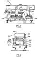
- FIGS 1 and 2 depict an embodiment of a differential impulse conveyor 180 according to the present invention.
- the tray 16 is driven directly by a round linear motor 30 as previously discussed, with the plunger or armature 26 being connected directly to a bracket 184, which is fixed to the tray 16.
- the round linear motor 40 is directly connected to the counterweight 50.
- the stators of both the motors 30, 40 may be secured to the center support 182 which is fixed to the base 12.
- the tray 16 is supported by two rearward arms 192 and two similar forward arms 200.
- the rearward arms 192 are each mounted on a conventional linear bearing 190 to slide along fixed shaft 188, which is supported by the spaced apart supports 186 secured to the base 12.
- Each of the tray supports 200 is similarly supported on a linear bearing 198 which slides along the fixed shaft 196.
- Each shaft 196 is supported at its forward end by a vertical support 194 each secured to the base 12.
- both the counterweight 50 and the linear bearing 198 may optionally be spaced between the pair of vertical supports 194.
- each of the linear motors 30 and 40 may be centrally spaced between the tray support members 192.
- Each of the linear bearings in the motors 30 and 40 may be of the type conventionally provided in round linear motors, or alternatively may be special linear bearings designed for more rugged application.
- the bearings 190 and 198 for the tray supports may also be conventional linear bearings, and may either be the type which utilizes a brass bushing or a ball bearing construction.
- Suitable linear bearings 190, 198 may be of the type manufactured by Thompson Industries, Inc. in Port Washington, N.Y.
- the tray 16 may be mounted closely adjacent the floor, since the drive mechanism requires very little height or space.
- the disadvantage of this embodiment is the use of numerous linear bearings both in the drive motor and for the tray and counterweight supports. Commercially available linear bearings may not have the desired long life as do the rubber bushings which preferably replace the linear bearings when the supports are pivotally mounted. Even if linear bearings can be obtained with this enhanced life, it is believed that the cost of the linear bearings which will achieve a life comparable to that of the rubber bushings as disclosed herein will be significantly greater than the cost of the rubber bushings.
- the tray connected member for interconnecting the linear motor and the tray is simply a bracket 184 which is secured to the tray 16, and is also secured to the armature of the linear motor.
- the tray connect member which interconnects the tray 16 and the linear motor may include one or more of the tray support members 18, 20 which in turn are pivotally connected to at least one end to base 12 or the tray 16.
- the armature may be fixed directly to the tray, in which case the only tray connect member which interconnects the linear motor to the tray is the securing member which attaches the motor armature to the tray.
- bracket, clevis or arm arrangements may be utilized for interconnecting the armature of a linear motor to the tray 16.
- FIGS 3 and 4 depict yet another embodiment of a differential impulse conveyor 210 according to the present invention.
- This embodiment utilizes a flat plate linear motor 225 having a stator 226 secured to the spaced uprights 212 and 214, each affixed to the base 12.
- the flat plate armature 224 for the drive motor 225 is secured to the crosspiece 232 which extending between the tray support members 222.
- the motor for driving the counterweight 50 includes a stator 228 also fixed to the supports 212, 214, and a flat plate armature 230 secured to the top of the counterweight 50.
- Another cross member 234 extends between the linear bearings 216 and between the linear bearings 218 to support the counterweight 50.
- a pair of fixed shafts 234 each extend between the supports 212, 214, and then continues on to be supported by a respective forward support 194.
- Each of the linear bearings 216, 220, 218 and 198 is thus linearly movable along a respective shaft 234 during operation of the differential impulse conveyor 210.
- Use of these linear bearings avoids the problem with the varying air gap between the flat plate stators and the flat plate armatures, but as previously noted introduces the additional factors of cost and poor service life for the use of linear bearings.
- a particular advantage of the embodiment shown in Figures 3 and 4 is the use of a linear motor with a flat plate stator and armature, with each of the stator and armature being centered over linear bearings 220 to provide high rigidity and to precisely locate the armature with respect to the stator.
- the motor for driving the tray 16, and particularly the motor armature 224 is connected to either the tray 26 or is connected to at least one of the tray support members 222.
- the linear bearing 220 is positioned horizontally in line with the linear motor (in a direction of movement of the goods along the elongate tray) such that the center of gravity of the armature 224 is vertically in line with (directly over for the embodiment shown) the linear bearing 220.
- This spacing of the motor armature and the linear bearing increases the likelihood of maintaining a substantially constant air gap between the linear motor stator and the linear motor armature. If the motor armature 224 is connected to one of the pair of tray support members, then that member, e.g., 222, is also vertically in line with the armature. This vertical alignment of the tray support member 222, the linear bearing 220 and the linear motor thus contribute to the long service life of the conveyor and also to the high efficiency of the linear motor.
- tray armature 224 may be attached to the crosspiece 232 extending between the pair of tray support members 222 and thus between the pair of linear bearings 220.
- the linear motor for this embodiment has a benefit of being structurally separate from the tray, thereby allowing the drive unit and the tray to be manufactured and replaced as separate components.
- a significant advantage of the embodiment shown in Figures 3 and 4 is the reduced overall height of the drive unit, which is achieved by the use of the flat plate linear motor and the linear bearing. The tendency of a flat plate stator and a flat plate armature to pull together during operation of the motor is thus reduced by providing the supports 222 and the linear bearings 220 centered with respect to the flat plate stator and the flat plate armature. If desired, additional linear bearings (not shown) may be used between the armature and stator to maintain the constant air gap between the flat plate stator and the respective flat plate armature.
- Linear bearings 150 as discussed herein may thus be used in conjunction with the tray support members 18, 20 and the armature support members 52, 53.
- each of these support members may be pivotally connected at a lower end to the base 12, with the linear bearing 150 as shown in Figures 6 and 7 then used to interconnect the upper end of each support member with the tray 16 or the counterweight 50, respectively.
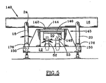
- Figure 5 depicts another embodiment of a differential impulse conveyor 140 which utilizes a linear motor 145 having a flat plate stator 142 and a flat plate armature 144.
- the flat plate stator 142 is secured to the base 12, while the flat plate armature 144 is secured to the tray 16.
- a corresponding flat plate stator 146 is secured to the base 12 and a flat plate armature 148 is secured to the counterweight 50 to drive the counterweight 50, as previously described.
- the tray 16 is supported by tray supports 18 and 20 which are each pivotally connected at 24 to the tray 16.
- the counterweight 50 includes four support members 52, 53 each also pivotally connected to the counterweight 50.
- the desired constant air gap between the stator and the armature is obtained by utilizing a special linear bearing 150 at the lower end of the support members 18, 20, 52 and 53.
- this linear bearing 150 thus allows the tray and the counterweight to be reciprocated by the respective motor without changing the air gap between the motor stator and the motor armature, and also allows the overall height of the conveyor to be significantly reduced.
- FIGS. 6 and 7 illustrate in further detail the linear bearing 150 used in conjunction with one of the tray support members 20.
- the tray support member 20 is provided with a pin 154 which interconnects the tray support member 20 with the tray 16, and which allows pivoting rotation of the tray support member 20 with respect to the pan about axis 24.
- the lower end of the tray support member 20 is provided with a curved end surface 152, with this curved end surface 152 having a selected radius such that its center coincides with the pivot axis 24.
- the base 12 has a pocket 156 therein for receiving the lower end of the tray support member 20, and a curved contact surface 158 is provided for engagement with the curved end surface 152.
- the curved contact surface 158 has a radius which is twice the radius of the end surface 152, with the center of this radius being spaced directly above the axis 24 for the embodiment shown in Figure 6 .
- the tray 16 may be moved in a purely horizontal manner during reciprocation of the tray support members 18, 20 by the linear motor in order to avoid a changing air gap between the motor stator and armature.
- the linear bearing 150 as shown in Figure 6 accomplishes this result by ensuring that the end surface 152 rocks slightly back and forth along the contact surface 158, but the controlled radius of these contact surfaces ensures that during this rocking action the pivot axis 24 moves horizontally back and forth, and not in an arcuate path.
- Figures 6 and 7 depict two arrangements to ensure that no sliding action occurs between the end surface 152 and the contact surface 158.
- the pair of guide ears or pins 168 and 170 extend outward from the left and right sides of the support member 20. Each of these pins move within a respective slot 172, 174 affixed in the base 12, with this slot having a central axis aligned with the pivot access 24.
- the extending pins 168 and 170 are guided by the respective slots 172 and 174 to ensure that these pins can only move in a direction linearly toward the pivot axis 124.
- a horizontal centerline of the pins 168 and 170 passes through the point of engagement of the surfaces 152 and 158 to ensure straight line linear motion of the axis 24. Accordingly, this guiding function served by the pins and slots ensures that the end surface 152 will not be allowed to slide along the contact surface 158.
- the lowermost ends 160 and 162 of the support member 20 thus straddle the contact surface 158 and rock within the respective pocket 164 and 166 as shown in Figure 7 .
- These lower ends 160 and 162 provide support for the pins 168 and 170, although other arrangements could be provided.
- straddling the central support 157 which includes the contact surface 158 these lower ends 160 and 162 thus prevent any undesirable movement of the support arm to the right or to the left as shown in the Figure 7 view.
- Figure 6 discloses another arrangement for ensuring that undesirable sliding between the end surface 152 and the contact surface 158 does not occur.
- the ears in the slots may be eliminated, and instead both the end surface 152 and the contact surface 158 may be provided with inter-engaging teeth 188 and 190, respectively.
- the mating engagement of these teeth allow for the slight rocking action necessary to accomplish the purposes of the invention, and effectively prevent any undesirable sliding of these surfaces.
- These inter-engaging teeth may be formed as conventional gear teeth on the end surfaces, or alternatively one of the gear teeth may be replaced with a section of a timing belt rigidly secured to that surface, with the teeth and the timing belt designed to engage corresponding teeth on the opposing end surface or on a mating timing belt.
- the centerline contour of these teeth nevertheless define a curved surface which, as explained above, satisfies the relationship wherein the centerline of the teeth for the end surface 152 coincides with the pivot axis 124, and the centerline for the teeth 190 on the surface 158 has a radius twice that of the surface 152.
- the radius for the surfaces 152 and 158 depicted in Figure 6 are for a very short support arm for clarity of the concept, and that when used as a linear bearing for supporting a tray of a differential impulse conveyor, these surfaces typically would have a radius substantially greater than that shown in Figure 6 .
- Figures 6 and 7 also depict an arrangement to eliminate the debris from entering the pocket 156 which receives a lower end of the tray support member 20.
- a conventional bellows 176 which may be made from a rubber-like material, may be secured at one end or four sides of the tray support member 20, and secured at the other end to the base 12. The bellows 176 thus prevents material from entering the pocket 156 for receiving the lower end of the support member 20.
- the linear bearing as discussed herein has utility apart from its use with differential impulse conveyors.
- linear bearing concept of the present invention may thus be employed in various applications, and in particular in applications such as robotics and machine tool operations which provide a connector pivotally connected at one end, with the desire that the movable member connected thereto move linearly in a straight line rather than in an arcuate path.
- Other devices which may benefit from the improved linear bearing of this invention include sewing machines, reciprocating saws (jig, saber, or hack), jack hammers, reciprocating motors, drill presses, industrial punches and forming machines.
- the typical linear bearing now used in many of these devices consists of a bushing, commonly fabricated from brass, nylon, or TeflonTM, mounted in a stationary housing with a reciprocating shaft passing through the bushing to provide location and alignment for the reciprocating shaft.
- linear bearings as disclosed herein will have application and utility.
- the improved linear bearing provides advantages in at least these three areas due to its rolling, rather than sliding motion: (1) reduced wear, (2) larger contact area and thus larger load capability, and (3) metal to metal location for high accuracy.
- a plurality of linear bearings as disclosed herein may accordingly be positioned circumferentially about each end of a reciprocating shaft, such as a linear motor shaft, to provide the desired alignment of the shaft during its movement with respect to the stationary member.
- the invention as shown in Figures 6 and 7 envisions a connector for interconnecting any stationary member with a movable member, with the movable member being linearly movable relative to the stationary in response to a forward and reverse movement of the connector relative to the stationary member.
- the pivot thus interconnects one end of the connector with either the stationary member or the movable member such that the connector pivots about a pivot axis fixed relative to the connector.
- the connector is a support which pivots about the axis 24 which is fixed relative to the movable member, although for other applications the pivot may interconnect the connector with the fixed member so that the connector pivots about the pivot axis fixed relative to both that end of the pivot and the fixed member.
- the opposing end of the connector thus includes a curved end surface having a radius with a center which lies along the pivot axis.
- a contact surface is secured to the other of the stationary member and the movable member and serves as an engagement surface for the end surface.
- this contact surface has a radius twice the radius of the end surface, with the contact surface center being spaced along a line which interconnects the engagement point between the contact surface and the end surface and the pivot axis. This 1:2 ratio of the radius for these contacting surfaces, when combined with a mechanism to ensure that no sliding of the end surface occurs with respect to the contact surface, thus ensures that linear movement of the movable member relative the stationary member will be obtained.
- each counterweight may be provided with its own linear drive motor.
- the drive motor for the tray may also drive each of the two or more counterweights.
- one linear motor is provided for driving the tray, and one linear motor is provided for driving each of the two or more counterweights.
- the counterweight 50 includes a plurality of plates, which are simplistically depicted as plates 50A, 50B, and 50C, respectively. Each of these plates may be easily added and removed from the remaining weight of the counterweight by a conventional mounting arrangement, such as hooks, bolt supports 51, or other conventional supporting member.
- the weight of the counterweight may thus be easily varied by adding or deleting additional plates 50A, 508 and 50C to any end, side, or bottom of the counterweight assembly. This allows the weight of the counterweight assembly.to easily match to the weight of the tray, so that the same basic counterweight assembly may be used for different sized trays, with the addition of plates 50A, 50B, and 50C for the heavier trays.
- base as used herein is intended in its general sense to mean the stationary member for supporting the tray supports, which in turn support the tray.
- the base as shown herein may be simply supported by the floor.
- the base could alternatively be hung from the ceiling by rods extending upward past the tray.
- the base nevertheless serves the function and purpose described herein.
Landscapes
- Engineering & Computer Science (AREA)
- Mechanical Engineering (AREA)
- Physics & Mathematics (AREA)
- Electromagnetism (AREA)
- Non-Mechanical Conveyors (AREA)
- Linear Motors (AREA)
- Reciprocating, Oscillating Or Vibrating Motors (AREA)
- Control Of Vehicles With Linear Motors And Vehicles That Are Magnetically Levitated (AREA)
- Structure Of Belt Conveyors (AREA)
- Transmission Devices (AREA)
Claims (7)
- Differenzial-Impulsförderer zum Bewegen von Gütern, mit:einem Förderergestell (12);einer Mulde (16) mit einem Muldenboden zur Aufnahme der Güter, wobei die Mulde (16) in einer Vorwärtsrichtung bewegbar ist, um die Güter während der Mulden-Vorwärtsbewegung vorwärts zu bewegen, und wobei die Mulde (16) in einer Rückwärtsrichtung bewegbar ist, um Güter während der Mulden-Rückwärtsbewegung entlang der Mulde zu verrutschen;einem Paar Muldenstützen (192, 200), die das Förderergestell (12) und die Mulde (16) verbinden, wobei jede Muldenstütze (192, 200) in Bezug auf das Förderergestell (12) linear beweglich und an der Mulde befestigt ist; und miteinem elektrisch betriebenen Linearmotor (30), der dazu eingerichtet ist, die Mulde (16) unter elektrischem Antrieb in der rückwärtigen Richtung zu bewegen, um die Rückwärtsbewegung zu erzeugen, wobei der Linearmotor (30) einen Anker (26) hat, der in Bezug auf einen Stator (28) in einer hin- und hergehenden Weise bewegbar ist,dadurch gekennzeichnet, dass der Linearmotor (30) geeignet ist, die Mulde (16) unter elektrischem Strom in der Vorwärtsrichtung zu bewegen, um die Vorwärtsbewegung zu erzielen.
- Differenzial-Impulsförderer nach Anspruch 1, weiterhin mit:einem Anker (224), der entweder mit der Mulde (16) oder mit mindestens einem der Paare von Muldenstützen (200, 222) verbunden ist;einem Paar von Linearlagern (198, 220) jeweils zur Führung der linearen Bewegung einer zugehörigen Muldenstütze (200, 222) bezüglich des Förderergestells (12); und wobeieines der Paare der Linearlager (220) horizontal in einer Linie mit dem Linearmotor (225) angeordnet ist, so dass ein Schwerpunkt des Ankers (224) mit dem entsprechenden der zugehörigen Linearlager (220) vertikal in einer Linie ist.
- Differenzial-Impulsförderer nach Anspruch 1 oder 2, bei dem sowohl der Anker (224) als auch der Stator (226) flache Platten sind.
- Differenzial-Impulsförderer nach Anspruch 1, bei dem jeder Stator (226) und Anker (224) flache Platten sind, die über einem Linearlager zentriert sind, das die lineare Bewegung von einer der Muldenstützen (222) führt.
- Differenzial-Impulsförderer nach Anspruch 1, weiterhin mit:dem Stator (28), der eine elektrische Spule umfasst, die den Anker (26) zirkumferenziell umschlingt, so dass der Stator (28) durch den Anker (26) hindurch reicht, um den Anker (26) in einer hin- und hergehenden Weise zu bewegen; undeiner Mulden-Halterung (184) zur Befestigung des Ankers an der Mulde (16).
- Differenzial-Impulsförderer nach einem der vorhergehenden Ansprüche, weiterhin mit:einem Gegengewicht (50), dass bezüglich der Basis (12) während der Vorwärtsbewegung der Mulde (16) in einer Rückwärtsrichtung und während einer Rückwärtsbewegung der Mulde (16) in einer Vorwärtsrichtung beweglich ist; undeinem weiteren elektrisch angetriebenen Linearmotor (40; 228, 230) zur Bewegung des Gegengewichts in der Rückwärts- und Vorwärtsrichtung, wobei der weitere Linearmotor einen weiteren Stator (128), der an dem Förderergestell (12) befestigt ist, und einen weiteren Anker (250) aufweist, der an dem Gegengewicht (50) befestigt ist.
- Differenzial-Impulsförderer nach einem der vorhergehenden Ansprüche, bei dem der Motor (30) unterhalb und zwischen den Enden der Mulde (16) angeordnet ist.
Applications Claiming Priority (2)
| Application Number | Priority Date | Filing Date | Title |
|---|---|---|---|
| US09/215,582 US6189683B1 (en) | 1998-12-17 | 1998-12-17 | Differential impulse conveyor with linear motor drive |
| EP99967353A EP1159211B1 (de) | 1998-12-17 | 1999-12-16 | Hin- und hergehender förderer mit linearmotorantrieb |
Related Parent Applications (1)
| Application Number | Title | Priority Date | Filing Date |
|---|---|---|---|
| EP99967353A Division EP1159211B1 (de) | 1998-12-17 | 1999-12-16 | Hin- und hergehender förderer mit linearmotorantrieb |
Publications (3)
| Publication Number | Publication Date |
|---|---|
| EP1714922A2 EP1714922A2 (de) | 2006-10-25 |
| EP1714922A3 EP1714922A3 (de) | 2006-11-15 |
| EP1714922B1 true EP1714922B1 (de) | 2009-10-28 |
Family
ID=22803548
Family Applications (2)
| Application Number | Title | Priority Date | Filing Date |
|---|---|---|---|
| EP99967353A Expired - Lifetime EP1159211B1 (de) | 1998-12-17 | 1999-12-16 | Hin- und hergehender förderer mit linearmotorantrieb |
| EP06014691A Expired - Lifetime EP1714922B1 (de) | 1998-12-17 | 1999-12-16 | Hin- und hergehender Förderer mit Linearmotorantrieb |
Family Applications Before (1)
| Application Number | Title | Priority Date | Filing Date |
|---|---|---|---|
| EP99967353A Expired - Lifetime EP1159211B1 (de) | 1998-12-17 | 1999-12-16 | Hin- und hergehender förderer mit linearmotorantrieb |
Country Status (7)
| Country | Link |
|---|---|
| US (2) | US6189683B1 (de) |
| EP (2) | EP1159211B1 (de) |
| AT (2) | ATE344204T1 (de) |
| AU (1) | AU769266B2 (de) |
| CA (2) | CA2354615C (de) |
| DE (2) | DE69941611D1 (de) |
| WO (1) | WO2000035787A1 (de) |
Families Citing this family (36)
| Publication number | Priority date | Publication date | Assignee | Title |
|---|---|---|---|---|
| US6189683B1 (en) * | 1998-12-17 | 2001-02-20 | Paul A. Svejkovsky | Differential impulse conveyor with linear motor drive |
| US6899218B2 (en) * | 2000-04-10 | 2005-05-31 | Magnetic Products, Inc. | Pneumatically actuated beltless conveyor |
| AU2001251531A1 (en) | 2000-04-10 | 2001-10-23 | Magnetic Products, Inc. | Pneumatically actuated beltless conveyor |
| US6655523B2 (en) * | 2001-03-15 | 2003-12-02 | Key Technology, Inc. | Excited frame conveyor and excitation process for same |
| JP4620285B2 (ja) * | 2001-05-14 | 2011-01-26 | 富士機械製造株式会社 | 電気部品装着システムの運転方法 |
| US7624894B2 (en) * | 2002-05-31 | 2009-12-01 | William Olin Gerold | Automated pill-dispensing apparatus |
| US7210598B2 (en) * | 2002-05-31 | 2007-05-01 | Microfil, Llc | Authomated pill-dispensing apparatus |
| WO2005028344A1 (en) * | 2003-09-17 | 2005-03-31 | Fmc Technologies, Inc. | Vibratory conveyor apparatus |
| US20050263375A1 (en) * | 2004-05-11 | 2005-12-01 | Tna Australia Pty Limited | Slip conveyor |
| US7754984B2 (en) * | 2005-01-20 | 2010-07-13 | Ishida Co., Ltd. | Transportation device and combinational weighing apparatus including the same |
| US7650986B2 (en) * | 2005-07-22 | 2010-01-26 | Magnetic Products, Inc. | Shaker conveyor assembly having an electronically controllable stroke speed |
| US20070193858A1 (en) * | 2006-02-22 | 2007-08-23 | Triple/S Dynamics, Inc. | Reciprocating conveyor system and method |
| US7712513B1 (en) * | 2006-04-04 | 2010-05-11 | Carrier Vibrating Equipment Co. | System and method for controlling casting shakeout retention |
| US8141714B2 (en) * | 2006-12-21 | 2012-03-27 | M-I Llc | Linear motors for shaker motion control |
| US7814666B2 (en) * | 2007-02-13 | 2010-10-19 | Robert Bosch Gmbh | Linkage drive mechanism for a reciprocating tool |
| US8549762B2 (en) * | 2007-02-13 | 2013-10-08 | Robert Bosch Gmbh | Linkage drive mechanism for a reciprocating tool |
| US8752695B2 (en) * | 2007-04-05 | 2014-06-17 | Magnetic Products, Inc. | Electric shaker conveyor assembly |
| DE102007031639B4 (de) * | 2007-07-06 | 2010-07-22 | Feintool International Holding | Vibrationslinearförderer |
| DK2011751T3 (da) * | 2007-07-06 | 2011-10-24 | Afag Holding Ag | Lineær vibrationstransportør |
| US7975837B2 (en) * | 2009-12-11 | 2011-07-12 | Heat And Control, Inc. | Conveyor with safety gate |
| US8066114B2 (en) | 2010-04-06 | 2011-11-29 | Paul Svejkovsky | Differential impulse conveyor with improved drive |
| US8561788B2 (en) | 2011-08-25 | 2013-10-22 | Paul Svejkovsky | Differential impulse conveyor with improved tray |
| US9126765B2 (en) | 2013-05-13 | 2015-09-08 | Key Technology, Inc. | Linear motion conveyor |
| US9609891B2 (en) | 2014-02-21 | 2017-04-04 | Kenneth C. Petri | Tumble drum for flavoring food portions |
| US9415941B2 (en) * | 2014-08-14 | 2016-08-16 | Key Technology, Inc | Vibration generating assembly |
| US9181037B1 (en) * | 2014-08-14 | 2015-11-10 | Key Technology, Inc. | Conveyor assembly |
| US9452890B2 (en) | 2014-10-17 | 2016-09-27 | Smalley Manufacturing Co., Inc. | Linear wave motion conveyor |
| CN104709661B (zh) * | 2014-12-31 | 2016-11-16 | 迈得医疗工业设备股份有限公司 | 一种输液器组装机夹具的输送装置 |
| WO2017003540A1 (en) * | 2015-06-30 | 2017-01-05 | Key Technology, Inc. | Vibration generating assembly |
| CN106364854A (zh) * | 2016-11-02 | 2017-02-01 | 新乡市振英机械设备有限公司 | 一种电机振动给料机 |
| PT3752426T (pt) | 2018-02-17 | 2022-01-31 | Svejkovsky Paul Blake | Sistema e método para carregar, transportar e descarregar produtos frangíveis |
| US10974907B2 (en) | 2018-10-11 | 2021-04-13 | Precision, Inc. | Horizontal motion conveyors and methods for reversing such conveyors |
| USD899022S1 (en) | 2018-10-12 | 2020-10-13 | Precision, Inc. | Conveyor frame |
| US11046528B2 (en) | 2019-04-25 | 2021-06-29 | Precision, Inc. | Horizontal motion conveyors having multiple drives |
| US11358801B2 (en) * | 2020-06-12 | 2022-06-14 | Paul Blake Svejkovsky | Differential impulse conveyor |
| US11939168B2 (en) * | 2021-10-08 | 2024-03-26 | TriDelta Systems, LLC | Servo-driven vibratory conveyor |
Family Cites Families (16)
| Publication number | Priority date | Publication date | Assignee | Title |
|---|---|---|---|---|
| DE916381C (de) * | 1950-07-20 | 1954-08-09 | Hans Blatzheim | Wurffoerdertisch mit Schwingmotor |
| US3197887A (en) * | 1962-07-27 | 1965-08-03 | Fuller Co | Cement clinker cooler comprising roller-bearing supported vibrating grates |
| US3263802A (en) * | 1962-11-07 | 1966-08-02 | Oliver A Haley | Vibratory conveyor |
| US3276307A (en) * | 1965-11-17 | 1966-10-04 | Soule Steel Company | Conveying apparatus for metal shears |
| GB1256225A (en) * | 1968-03-19 | 1971-12-08 | Driver Southall | Improvements in vibratory feeders |
| US4356911A (en) * | 1980-07-18 | 1982-11-02 | Fmc Corporation | Linear drive unit for vibratory conveyor |
| US5178258A (en) * | 1990-01-25 | 1993-01-12 | Smalley Alfred E | Inertial conveyor system |
| NL9000894A (nl) * | 1990-04-17 | 1991-11-18 | Johannes Elisabeth Jozef Vlugg | Werkwijze en inrichting voor het verplaatsen van een voorwerp. |
| US5409101A (en) | 1994-02-03 | 1995-04-25 | Allen Fruit Co., Inc. | Variably-controlled vibratory conveyor |
| US5351807A (en) | 1994-03-23 | 1994-10-04 | Paul Svejkovsky | Drive mechanism for a linear motion conveyor |
| US5460259A (en) * | 1994-06-03 | 1995-10-24 | Food Engineering Corporation | Conveyor support apparatus for straight-line motion |
| US6237748B1 (en) * | 1996-03-08 | 2001-05-29 | Netter Gmbh | Oscillating drive for resonance system |
| US5794757A (en) | 1996-03-15 | 1998-08-18 | Paul A. Svejkovsky | Differential impulse conveyor and method |
| US5842678A (en) | 1997-04-15 | 1998-12-01 | Svejkovsky; Paul A. | Machinery mount |
| US6105753A (en) * | 1997-08-14 | 2000-08-22 | Graham; S. Neal | Linear vibratory parts feeder |
| US6189683B1 (en) * | 1998-12-17 | 2001-02-20 | Paul A. Svejkovsky | Differential impulse conveyor with linear motor drive |
-
1998
- 1998-12-17 US US09/215,582 patent/US6189683B1/en not_active Expired - Lifetime
-
1999
- 1999-12-16 WO PCT/US1999/029888 patent/WO2000035787A1/en not_active Ceased
- 1999-12-16 AT AT99967353T patent/ATE344204T1/de not_active IP Right Cessation
- 1999-12-16 EP EP99967353A patent/EP1159211B1/de not_active Expired - Lifetime
- 1999-12-16 CA CA002354615A patent/CA2354615C/en not_active Expired - Fee Related
- 1999-12-16 DE DE69941611T patent/DE69941611D1/de not_active Expired - Lifetime
- 1999-12-16 EP EP06014691A patent/EP1714922B1/de not_active Expired - Lifetime
- 1999-12-16 DE DE69933894T patent/DE69933894T2/de not_active Expired - Lifetime
- 1999-12-16 AU AU23647/00A patent/AU769266B2/en not_active Expired
- 1999-12-16 AT AT06014691T patent/ATE446931T1/de not_active IP Right Cessation
- 1999-12-16 CA CA002593338A patent/CA2593338C/en not_active Expired - Fee Related
-
2001
- 2001-02-16 US US09/788,153 patent/US6527104B2/en not_active Expired - Lifetime
Also Published As
| Publication number | Publication date |
|---|---|
| EP1714922A2 (de) | 2006-10-25 |
| EP1159211A4 (de) | 2003-09-17 |
| EP1159211B1 (de) | 2006-11-02 |
| AU2364700A (en) | 2000-07-03 |
| CA2354615A1 (en) | 2000-06-22 |
| EP1159211A1 (de) | 2001-12-05 |
| WO2000035787A1 (en) | 2000-06-22 |
| ATE344204T1 (de) | 2006-11-15 |
| US20010007300A1 (en) | 2001-07-12 |
| DE69933894T2 (de) | 2007-04-26 |
| CA2593338A1 (en) | 2000-06-22 |
| DE69941611D1 (de) | 2009-12-10 |
| CA2354615C (en) | 2008-06-03 |
| DE69933894D1 (de) | 2006-12-14 |
| AU769266B2 (en) | 2004-01-22 |
| US6527104B2 (en) | 2003-03-04 |
| CA2593338C (en) | 2009-12-15 |
| EP1714922A3 (de) | 2006-11-15 |
| US6189683B1 (en) | 2001-02-20 |
| ATE446931T1 (de) | 2009-11-15 |
Similar Documents
| Publication | Publication Date | Title |
|---|---|---|
| AU769266B2 (en) | Differential impulse conveyor with linear motor drive | |
| US6029796A (en) | Two way vibratory conveyor | |
| US4651869A (en) | Apparatus having a vibratory drive for the feeding of workpieces in rows | |
| EP0662925B1 (de) | Transversalförderer für längliche Holzstücke | |
| EP2996971B1 (de) | Förderer mit linearbewegung | |
| US6705459B1 (en) | Two-way vibratory feeder | |
| JP2000506482A (ja) | 差動インパルス型コンベアと方法 | |
| EP1279626B1 (de) | Fördervorrichtung für Gegenstände | |
| CN115734923A (zh) | 差分脉冲输送机 | |
| EP1094241A2 (de) | Motorlager für schwingende Einrichtung | |
| US20070193858A1 (en) | Reciprocating conveyor system and method | |
| US6435337B1 (en) | Rotary drive for vibratory conveyors | |
| US4724949A (en) | Conveyor apparatus for discharging pressed products and similar items from a press | |
| CN214161819U (zh) | 用于激光切割机自动上料的链传动装置 | |
| US20250376334A1 (en) | Pendulum conveyor | |
| CN202687358U (zh) | 细粉料振动输送机 | |
| CN114382854A (zh) | 一种机械运动方式圆盘旋转体作曲线往复运动 | |
| EP0453041B1 (de) | Schwingförderer | |
| CN219005410U (zh) | 一种切割机床的进料装置 | |
| JPH0242657Y2 (de) | ||
| CA2541539C (en) | Differential horizontal motion conveyor and drive mechanism | |
| JPH0736981B2 (ja) | 石材切断装置 |
Legal Events
| Date | Code | Title | Description |
|---|---|---|---|
| PUAI | Public reference made under article 153(3) epc to a published international application that has entered the european phase |
Free format text: ORIGINAL CODE: 0009012 |
|
| PUAL | Search report despatched |
Free format text: ORIGINAL CODE: 0009013 |
|
| 17P | Request for examination filed |
Effective date: 20060714 |
|
| AC | Divisional application: reference to earlier application |
Ref document number: 1159211 Country of ref document: EP Kind code of ref document: P |
|
| AK | Designated contracting states |
Kind code of ref document: A2 Designated state(s): AT BE CH CY DE DK ES FI FR GB GR IE IT LI LU MC NL PT SE |
|
| AK | Designated contracting states |
Kind code of ref document: A3 Designated state(s): AT BE CH CY DE DK ES FI FR GB GR IE IT LI LU MC NL PT SE |
|
| RIN1 | Information on inventor provided before grant (corrected) |
Inventor name: SVEJKOVSKY, PAUL B. Inventor name: SVEJKOVSKY, PAUL A. Inventor name: KNODELL, THOMAS G., JR. |
|
| AKX | Designation fees paid |
Designated state(s): AT BE CH CY DE DK ES FI FR GB GR IE IT LI LU MC NL PT SE |
|
| GRAP | Despatch of communication of intention to grant a patent |
Free format text: ORIGINAL CODE: EPIDOSNIGR1 |
|
| GRAS | Grant fee paid |
Free format text: ORIGINAL CODE: EPIDOSNIGR3 |
|
| GRAA | (expected) grant |
Free format text: ORIGINAL CODE: 0009210 |
|
| AC | Divisional application: reference to earlier application |
Ref document number: 1159211 Country of ref document: EP Kind code of ref document: P |
|
| AK | Designated contracting states |
Kind code of ref document: B1 Designated state(s): AT BE CH CY DE DK ES FI FR GB GR IE IT LI LU MC NL PT SE |
|
| REG | Reference to a national code |
Ref country code: GB Ref legal event code: FG4D |
|
| REG | Reference to a national code |
Ref country code: CH Ref legal event code: EP |
|
| REG | Reference to a national code |
Ref country code: IE Ref legal event code: FG4D |
|
| REF | Corresponds to: |
Ref document number: 69941611 Country of ref document: DE Date of ref document: 20091210 Kind code of ref document: P |
|
| PG25 | Lapsed in a contracting state [announced via postgrant information from national office to epo] |
Ref country code: FI Free format text: LAPSE BECAUSE OF FAILURE TO SUBMIT A TRANSLATION OF THE DESCRIPTION OR TO PAY THE FEE WITHIN THE PRESCRIBED TIME-LIMIT Effective date: 20091028 Ref country code: ES Free format text: LAPSE BECAUSE OF FAILURE TO SUBMIT A TRANSLATION OF THE DESCRIPTION OR TO PAY THE FEE WITHIN THE PRESCRIBED TIME-LIMIT Effective date: 20100208 Ref country code: SE Free format text: LAPSE BECAUSE OF FAILURE TO SUBMIT A TRANSLATION OF THE DESCRIPTION OR TO PAY THE FEE WITHIN THE PRESCRIBED TIME-LIMIT Effective date: 20091028 Ref country code: PT Free format text: LAPSE BECAUSE OF FAILURE TO SUBMIT A TRANSLATION OF THE DESCRIPTION OR TO PAY THE FEE WITHIN THE PRESCRIBED TIME-LIMIT Effective date: 20100301 |
|
| PG25 | Lapsed in a contracting state [announced via postgrant information from national office to epo] |
Ref country code: CY Free format text: LAPSE BECAUSE OF FAILURE TO SUBMIT A TRANSLATION OF THE DESCRIPTION OR TO PAY THE FEE WITHIN THE PRESCRIBED TIME-LIMIT Effective date: 20091028 |
|
| PG25 | Lapsed in a contracting state [announced via postgrant information from national office to epo] |
Ref country code: BE Free format text: LAPSE BECAUSE OF FAILURE TO SUBMIT A TRANSLATION OF THE DESCRIPTION OR TO PAY THE FEE WITHIN THE PRESCRIBED TIME-LIMIT Effective date: 20091028 Ref country code: AT Free format text: LAPSE BECAUSE OF FAILURE TO SUBMIT A TRANSLATION OF THE DESCRIPTION OR TO PAY THE FEE WITHIN THE PRESCRIBED TIME-LIMIT Effective date: 20091028 |
|
| PG25 | Lapsed in a contracting state [announced via postgrant information from national office to epo] |
Ref country code: MC Free format text: LAPSE BECAUSE OF NON-PAYMENT OF DUE FEES Effective date: 20100701 Ref country code: DK Free format text: LAPSE BECAUSE OF FAILURE TO SUBMIT A TRANSLATION OF THE DESCRIPTION OR TO PAY THE FEE WITHIN THE PRESCRIBED TIME-LIMIT Effective date: 20091028 |
|
| REG | Reference to a national code |
Ref country code: CH Ref legal event code: PL |
|
| PLBE | No opposition filed within time limit |
Free format text: ORIGINAL CODE: 0009261 |
|
| STAA | Information on the status of an ep patent application or granted ep patent |
Free format text: STATUS: NO OPPOSITION FILED WITHIN TIME LIMIT |
|
| 26N | No opposition filed |
Effective date: 20100729 |
|
| PG25 | Lapsed in a contracting state [announced via postgrant information from national office to epo] |
Ref country code: CH Free format text: LAPSE BECAUSE OF NON-PAYMENT OF DUE FEES Effective date: 20091231 Ref country code: LI Free format text: LAPSE BECAUSE OF NON-PAYMENT OF DUE FEES Effective date: 20091231 Ref country code: GR Free format text: LAPSE BECAUSE OF FAILURE TO SUBMIT A TRANSLATION OF THE DESCRIPTION OR TO PAY THE FEE WITHIN THE PRESCRIBED TIME-LIMIT Effective date: 20100129 |
|
| PGFP | Annual fee paid to national office [announced via postgrant information from national office to epo] |
Ref country code: IE Payment date: 20101227 Year of fee payment: 12 Ref country code: FR Payment date: 20110107 Year of fee payment: 12 |
|
| PGFP | Annual fee paid to national office [announced via postgrant information from national office to epo] |
Ref country code: IT Payment date: 20101227 Year of fee payment: 12 |
|
| PG25 | Lapsed in a contracting state [announced via postgrant information from national office to epo] |
Ref country code: LU Free format text: LAPSE BECAUSE OF NON-PAYMENT OF DUE FEES Effective date: 20091216 |
|
| REG | Reference to a national code |
Ref country code: FR Ref legal event code: ST Effective date: 20120831 |
|
| REG | Reference to a national code |
Ref country code: IE Ref legal event code: MM4A |
|
| PG25 | Lapsed in a contracting state [announced via postgrant information from national office to epo] |
Ref country code: IE Free format text: LAPSE BECAUSE OF NON-PAYMENT OF DUE FEES Effective date: 20111216 |
|
| PG25 | Lapsed in a contracting state [announced via postgrant information from national office to epo] |
Ref country code: IT Free format text: LAPSE BECAUSE OF NON-PAYMENT OF DUE FEES Effective date: 20111216 |
|
| PG25 | Lapsed in a contracting state [announced via postgrant information from national office to epo] |
Ref country code: FR Free format text: LAPSE BECAUSE OF NON-PAYMENT OF DUE FEES Effective date: 20120102 |
|
| PGFP | Annual fee paid to national office [announced via postgrant information from national office to epo] |
Ref country code: GB Payment date: 20181227 Year of fee payment: 20 |
|
| PGFP | Annual fee paid to national office [announced via postgrant information from national office to epo] |
Ref country code: DE Payment date: 20181231 Year of fee payment: 20 Ref country code: NL Payment date: 20181226 Year of fee payment: 20 |
|
| REG | Reference to a national code |
Ref country code: DE Ref legal event code: R071 Ref document number: 69941611 Country of ref document: DE |
|
| REG | Reference to a national code |
Ref country code: NL Ref legal event code: MK Effective date: 20191215 |
|
| REG | Reference to a national code |
Ref country code: GB Ref legal event code: PE20 Expiry date: 20191215 |
|
| PG25 | Lapsed in a contracting state [announced via postgrant information from national office to epo] |
Ref country code: GB Free format text: LAPSE BECAUSE OF EXPIRATION OF PROTECTION Effective date: 20191215 |