EP1714923A2 - Transporteur à chaîne pour une machine de travail du bois - Google Patents
Transporteur à chaîne pour une machine de travail du bois Download PDFInfo
- Publication number
- EP1714923A2 EP1714923A2 EP06006984A EP06006984A EP1714923A2 EP 1714923 A2 EP1714923 A2 EP 1714923A2 EP 06006984 A EP06006984 A EP 06006984A EP 06006984 A EP06006984 A EP 06006984A EP 1714923 A2 EP1714923 A2 EP 1714923A2
- Authority
- EP
- European Patent Office
- Prior art keywords
- chain
- linear drive
- transport device
- workpiece transport
- parts
- Prior art date
- Legal status (The legal status is an assumption and is not a legal conclusion. Google has not performed a legal analysis and makes no representation as to the accuracy of the status listed.)
- Withdrawn
Links
- 230000005291 magnetic effect Effects 0.000 claims abstract description 9
- 230000005540 biological transmission Effects 0.000 description 1
- 230000001914 calming effect Effects 0.000 description 1
- 230000001419 dependent effect Effects 0.000 description 1
- 230000000694 effects Effects 0.000 description 1
- 239000003302 ferromagnetic material Substances 0.000 description 1
- 238000003754 machining Methods 0.000 description 1
- 230000010355 oscillation Effects 0.000 description 1
- 238000005096 rolling process Methods 0.000 description 1
- IHQKEDIOMGYHEB-UHFFFAOYSA-M sodium dimethylarsinate Chemical class [Na+].C[As](C)([O-])=O IHQKEDIOMGYHEB-UHFFFAOYSA-M 0.000 description 1
- 230000008961 swelling Effects 0.000 description 1
Images
Classifications
-
- B—PERFORMING OPERATIONS; TRANSPORTING
- B65—CONVEYING; PACKING; STORING; HANDLING THIN OR FILAMENTARY MATERIAL
- B65G—TRANSPORT OR STORAGE DEVICES, e.g. CONVEYORS FOR LOADING OR TIPPING, SHOP CONVEYOR SYSTEMS OR PNEUMATIC TUBE CONVEYORS
- B65G23/00—Driving gear for endless conveyors; Belt- or chain-tensioning arrangements
- B65G23/22—Arrangements or mountings of driving motors
- B65G23/23—Arrangements or mountings of driving motors of electric linear motors
-
- B—PERFORMING OPERATIONS; TRANSPORTING
- B65—CONVEYING; PACKING; STORING; HANDLING THIN OR FILAMENTARY MATERIAL
- B65G—TRANSPORT OR STORAGE DEVICES, e.g. CONVEYORS FOR LOADING OR TIPPING, SHOP CONVEYOR SYSTEMS OR PNEUMATIC TUBE CONVEYORS
- B65G54/00—Non-mechanical conveyors not otherwise provided for
- B65G54/02—Non-mechanical conveyors not otherwise provided for electrostatic, electric, or magnetic
Definitions
- the invention relates to a workpiece transport device according to the features of the preamble of patent claim 1.
- the drive of the endlessly circulating chain via a drive sprocket, to which the upper run of the chain runs and which deflects the chain at one of the two ends of the workpiece transport device.
- the drive sprocket has along its circumference with the chain engaging driving members whose connecting line is polygonal. Accordingly, the chain also wraps around the drive sprocket in a polygonal shape, and the chain links running onto the drive sprocket are angled out of the straight, elongated position of the chain around the corner angle of the polygon relative to one another.
- a drive rod has been provided for workpiece transport devices of the type in question for the drive of the chain, which is arranged in the region of one of the Kettentrume.
- the chain also runs on at least one drive sprocket, also here are transmitted to the chain pulsating feed forces.
- the drive block is an additional component which is more difficult to integrate into the overall device than a motor driving one of the idler sprockets.
- the invention takes a different approach by eliminating a drive sprocket, which causes the described polygon effect, from the outset.
- the invention has the object to provide a workpiece transport device of the type mentioned, with a vibration-free, but at least low-vibration circulation of the chain is achieved.
- For the invention is essential that the circulation or feed drive of the chain in the form of the electromagnetic linear motor works smoothly, so transmits uniform forces without load peaks on the chain. This conditional vibrations or vibrations both in the longitudinal direction of the chain and across it can therefore not occur. In a woodworking machine, which machined the workpieces in a fast pass, this not only reduces wear on the chain and the track, it also improves the quality of machining.
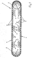
- the chain 1 is a chain which runs endlessly over two mutually opposite deflection devices 2, whose upper run 3 and lower run 4 preferably run parallel to one another.
- the chain 1 is arranged overall in the operating position in a vertical plane.
- the deflection devices 2 are curved runners for guiding the chain 1 in the two deflection regions, instead of which sprockets can be provided which are not driven.
- the circulation track for the chain 1 has the shape of a Stadionovals without further deflection points, as is the case for the Workpiece transport is most advantageous in fast-working woodworking machines.
- the chain 1 is composed of a plurality of hingedly interconnected chain links 5.
- rollers 6 are provided, which can each be located at the hinge point between two adjacent chain links 5.
- Figures 2 to 4 show further details of the chain links 5.
- a support plate 12 is disposed, which is exposed when passing through the upper strand 3 of the chain 1 upwards.
- This support plate 12 which are placed on the upper strand 3 of the chain 1 to be transported workpieces and on which the workpieces can be stretched if necessary.
- the rollers 6 are designed differently, so the pulleys 6 each shown on the left in Figures 2 to 4 at its periphery on a track profile in order to guide the chain 1 in its longitudinal direction safely.
- the rollers 6 run on rails 8, wherein the roller 6 associated with the track profile running rail 8 has a corresponding counter-profile 8.1.
- the rails 8 are part of guide devices 7, which can be arranged along the entire chain orbit.
- the primary parts 9 represent the fixed stator of the respective linear motor, accordingly, the primary parts 9 are fixedly arranged on the not shown in the drawing machine frame.
- the primary parts 9 cooperate with movable secondary parts 10, which are arranged on the side facing away from the support plate 12 sides of the chain links 5. The force exerted on the secondary parts 10 magnetic feed forces transmitted to the chain links 5 and thus to the entire chain 1.
- the individual primary parts 9 of the linear drive can also connect seamlessly to each other and depending on the length of the chain 1 to a single primary part be united with each other.
- primary parts 9 may be provided in the region of the deflecting devices 2, these primary parts 9, especially with their yokes, following the curvature of the chain orbit in the region of the deflecting devices 2.
- yokes 9.1 of the primary parts 9 which extend in a straight, planar orientation.
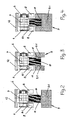
- Figure 3 shows a simpler solution for the arrangement of the primary part 9 and the secondary part 10 of the linear drive.
- the rectangular in cross-section Permamentmagneten as a secondary part 10 is located on its lower narrow surface side across the air gap 11 across the yoke 9.1 of the primary part 9 of the linear drive opposite. Since magnetic tensile forces are transmitted to the chain link 5, designs are preferred, as shown in Figures 3 and 4.
- the permanent magnet emerges as a secondary part 10 on the chain link 5 between two yokes 9.1 or yoke sections of the primary parts 9 of the linear drive. Due to the mirror-symmetrical arrangement relative to the vertical longitudinal center of the chain link 5, the orthogonal forces transferred to the two broad sides of the secondary part 10 over the air flow compensate each other.
- the two yokes 9.1 of the stationary primary part 9 are formed by a U-shaped yoke profile.
- the primary parts 9 of the linear drive can be blasted so that different feed forces are transmitted to the chain 1 in neighboring areas. This makes it possible to achieve a calming of the chain run in a critical region of the chain 1 in that the chain section passing through this region is either tightened or compressed.
- the tightening of the chain section is achieved by higher feed forces are transmitted to the chain 1 in a forward in the feed direction first range than in a lying behind against the feed direction area.
- the primary parts 9 act in this rear area, so to speak as a brake for the chain 1, in extreme cases, they can even transmit against the feed direction conveying forces on the chain 1.
Landscapes
- Engineering & Computer Science (AREA)
- Mechanical Engineering (AREA)
- Devices For Conveying Motion By Means Of Endless Flexible Members (AREA)
- Framework For Endless Conveyors (AREA)
Applications Claiming Priority (1)
| Application Number | Priority Date | Filing Date | Title |
|---|---|---|---|
| DE200510019036 DE102005019036A1 (de) | 2005-04-23 | 2005-04-23 | Werkstücktransportvorrichtung mit zumindest einer endlos umlaufenden Kette |
Publications (2)
| Publication Number | Publication Date |
|---|---|
| EP1714923A2 true EP1714923A2 (fr) | 2006-10-25 |
| EP1714923A3 EP1714923A3 (fr) | 2008-04-23 |
Family
ID=36695006
Family Applications (1)
| Application Number | Title | Priority Date | Filing Date |
|---|---|---|---|
| EP06006984A Withdrawn EP1714923A3 (fr) | 2005-04-23 | 2006-03-31 | Transporteur à chaîne pour une machine de travail du bois |
Country Status (2)
| Country | Link |
|---|---|
| EP (1) | EP1714923A3 (fr) |
| DE (1) | DE102005019036A1 (fr) |
Cited By (14)
| Publication number | Priority date | Publication date | Assignee | Title |
|---|---|---|---|---|
| US7721873B2 (en) | 2006-07-12 | 2010-05-25 | Homag Holzbearbeitungssysteme Ag | Chain link for a circulating transport of a machine tool, and double end tenoner with guide chain formed from said chain links |
| WO2010108509A1 (fr) * | 2009-03-25 | 2010-09-30 | Trumpf Werkzeugmaschinen Gmbh + Co. Kg | Entraînement linéaire électrique |
| EP2297007A1 (fr) * | 2008-07-07 | 2011-03-23 | Kaak, Johan Hendrik Bernard | Convoyeur à bande |
| WO2011131385A1 (fr) * | 2010-04-19 | 2011-10-27 | Robert Bosch Gmbh | Dispositif de transport pourvu d'un élément de transport articulé |
| ITBO20100435A1 (it) * | 2010-07-09 | 2012-01-10 | Flexlink Techne S R L | Convogliatore elettromagnetico ad anello chiuso per il trasporto di articoli |
| DE102011016039A1 (de) * | 2011-04-04 | 2012-03-08 | Jan-Peter Jastrzembski | Antrieb eines Förderers durch einen Linearmotor |
| WO2013034534A1 (fr) * | 2011-09-09 | 2013-03-14 | Weiss Gmbh | Dispositif de transport |
| CN103662715A (zh) * | 2012-09-23 | 2014-03-26 | 山西晋城无烟煤矿业集团有限责任公司 | 新型带式输送机 |
| WO2015028212A1 (fr) * | 2013-08-26 | 2015-03-05 | Robert Bosch Gmbh | Dispositif transporteur |
| ITUB20154256A1 (it) * | 2015-10-09 | 2017-04-09 | Univ Degli Studi Di Trieste | Macchina elettrica reversibile a struttura composita |
| EP3294652A4 (fr) * | 2015-05-15 | 2019-01-23 | Laitram, L.L.C. | Système de désempilage à rouleaux de transfert |
| IT201800001907A1 (it) * | 2018-01-25 | 2019-07-25 | Rexnord Flattop Europe S R L | Trasportatore di articoli |
| US20240409319A1 (en) * | 2021-10-27 | 2024-12-12 | Haka Groups Participacoes De Negocios S/A | Conveyor linear drive for continuous bulk material conveying device |
| EP4404447A4 (fr) * | 2021-09-13 | 2025-10-29 | Haka Groups Participacoes De Negocios S/A | Bande transporteuse à traction par moteur à induction linéaire avec primaire à double face et secondaire long sectionné |
Families Citing this family (1)
| Publication number | Priority date | Publication date | Assignee | Title |
|---|---|---|---|---|
| DE102008040204A1 (de) | 2008-07-07 | 2010-01-14 | Robert Bosch Gmbh | Vorrichtung und Verfahren zum Transportieren von Produkten mit Linearantrieb |
Citations (1)
| Publication number | Priority date | Publication date | Assignee | Title |
|---|---|---|---|---|
| EP1479944A2 (fr) | 2003-05-23 | 2004-11-24 | Siemens Aktiengesellschaft | Entraínement rotatif par chaíne, respectivement courroie et procédé d'opération |
Family Cites Families (15)
| Publication number | Priority date | Publication date | Assignee | Title |
|---|---|---|---|---|
| DE1953529A1 (de) * | 1969-10-24 | 1971-05-06 | Pohlig Heckel Bleichert | Foerdergeraet |
| CA923448A (en) * | 1969-11-28 | 1973-03-27 | The Dunlop Company Limited | Conveyors |
| US3731166A (en) * | 1970-05-15 | 1973-05-01 | Hitachi Ltd | Duplex driving system for an electrically operated moving object with an endless chain |
| FR2117759B1 (fr) * | 1970-12-15 | 1974-11-08 | Cytec France | |
| DE2636604A1 (de) * | 1976-08-13 | 1978-02-16 | Poisel Otto Karl | Antrieb einer transportkette mit hoher laufgeschwindigkeit |
| US4197933A (en) * | 1977-12-05 | 1980-04-15 | The Boeing Company | Linear induction drive system for accelerating and decelerating moving walkway |
| DE3543518A1 (de) * | 1985-12-10 | 1987-06-11 | Thyssen Industrie | Elektrisches antriebssystem fuer kettenfahrzeuge |
| DE4031925A1 (de) * | 1990-10-09 | 1992-04-16 | E & Pk Ingbuero | Kettenkratzfoerderer mit linearmotorantrieb |
| US5947361A (en) * | 1996-07-25 | 1999-09-07 | Emo Elektromotorenwerk Kamenz Gmbh | Apparatus for transporting fabrics and web-shaped material with an electric drive device |
| DE59800316D1 (de) * | 1998-05-13 | 2000-11-30 | Beumer Maschf Bernhard | Stückgutförderer (Sorter) mit Kipp-Förderelementen |
| DE19837915A1 (de) * | 1998-08-20 | 2000-03-02 | Otis Elevator Co | Linearantrieb für Fahrtreppen oder Fahrsteige |
| IT250110Y1 (it) * | 2000-05-16 | 2003-07-07 | Celaschi S P A | Perfezionamenti ai trasportatori continui di macchine utensili per lalavorazione del legno |
| JP2002019944A (ja) * | 2000-07-10 | 2002-01-23 | Hitachi Kiden Kogyo Ltd | 搬送装置 |
| DE10036913B4 (de) * | 2000-07-28 | 2005-05-04 | Otis Elevator Co., Farmington | Fahrtreppen- oder Fahrsteig-Antrieb |
| AU2003281676A1 (en) * | 2002-07-26 | 2004-02-16 | Crisplant A/S | A conveyor and a method of providing a driving force to a conveyor |
-
2005
- 2005-04-23 DE DE200510019036 patent/DE102005019036A1/de not_active Withdrawn
-
2006
- 2006-03-31 EP EP06006984A patent/EP1714923A3/fr not_active Withdrawn
Patent Citations (1)
| Publication number | Priority date | Publication date | Assignee | Title |
|---|---|---|---|---|
| EP1479944A2 (fr) | 2003-05-23 | 2004-11-24 | Siemens Aktiengesellschaft | Entraínement rotatif par chaíne, respectivement courroie et procédé d'opération |
Cited By (24)
| Publication number | Priority date | Publication date | Assignee | Title |
|---|---|---|---|---|
| US7721873B2 (en) | 2006-07-12 | 2010-05-25 | Homag Holzbearbeitungssysteme Ag | Chain link for a circulating transport of a machine tool, and double end tenoner with guide chain formed from said chain links |
| EP2297007A1 (fr) * | 2008-07-07 | 2011-03-23 | Kaak, Johan Hendrik Bernard | Convoyeur à bande |
| WO2010108509A1 (fr) * | 2009-03-25 | 2010-09-30 | Trumpf Werkzeugmaschinen Gmbh + Co. Kg | Entraînement linéaire électrique |
| WO2011131385A1 (fr) * | 2010-04-19 | 2011-10-27 | Robert Bosch Gmbh | Dispositif de transport pourvu d'un élément de transport articulé |
| US8827071B2 (en) | 2010-04-19 | 2014-09-09 | Robert Bosch Gmbh | Transporting apparatus with articulated conveying element |
| ITBO20100435A1 (it) * | 2010-07-09 | 2012-01-10 | Flexlink Techne S R L | Convogliatore elettromagnetico ad anello chiuso per il trasporto di articoli |
| WO2012004770A1 (fr) * | 2010-07-09 | 2012-01-12 | Flexlink Techne S.R.L. | Transporteur électromagnétique sans fin pour le transport d'articles |
| DE102011016039A1 (de) * | 2011-04-04 | 2012-03-08 | Jan-Peter Jastrzembski | Antrieb eines Förderers durch einen Linearmotor |
| WO2013034534A1 (fr) * | 2011-09-09 | 2013-03-14 | Weiss Gmbh | Dispositif de transport |
| EP3170774A1 (fr) * | 2011-09-09 | 2017-05-24 | Weiss GmbH | Dispositif de transport |
| CN103998358A (zh) * | 2011-09-09 | 2014-08-20 | 维斯公司 | 传送设备 |
| CN103998358B (zh) * | 2011-09-09 | 2016-10-12 | 维斯公司 | 传送设备 |
| CN103662715B (zh) * | 2012-09-23 | 2016-07-06 | 山西晋城无烟煤矿业集团有限责任公司 | 一种带式输送机 |
| CN103662715A (zh) * | 2012-09-23 | 2014-03-26 | 山西晋城无烟煤矿业集团有限责任公司 | 新型带式输送机 |
| WO2015028212A1 (fr) * | 2013-08-26 | 2015-03-05 | Robert Bosch Gmbh | Dispositif transporteur |
| US9856096B2 (en) | 2013-08-26 | 2018-01-02 | Robert Bosch Gmbh | Transporting arrangement |
| EP3294652A4 (fr) * | 2015-05-15 | 2019-01-23 | Laitram, L.L.C. | Système de désempilage à rouleaux de transfert |
| ITUB20154256A1 (it) * | 2015-10-09 | 2017-04-09 | Univ Degli Studi Di Trieste | Macchina elettrica reversibile a struttura composita |
| IT201800001907A1 (it) * | 2018-01-25 | 2019-07-25 | Rexnord Flattop Europe S R L | Trasportatore di articoli |
| WO2019145406A1 (fr) * | 2018-01-25 | 2019-08-01 | Rexnord Flattop Europe S.R.L. | Convoyeur d'articles |
| CN111655599A (zh) * | 2018-01-25 | 2020-09-11 | 莱克斯诺弗莱托普欧洲有限公司 | 物品输送机 |
| US11305943B2 (en) | 2018-01-25 | 2022-04-19 | Rexnord Flattop Europe S.R.L. | Conveyor of articles |
| EP4404447A4 (fr) * | 2021-09-13 | 2025-10-29 | Haka Groups Participacoes De Negocios S/A | Bande transporteuse à traction par moteur à induction linéaire avec primaire à double face et secondaire long sectionné |
| US20240409319A1 (en) * | 2021-10-27 | 2024-12-12 | Haka Groups Participacoes De Negocios S/A | Conveyor linear drive for continuous bulk material conveying device |
Also Published As
| Publication number | Publication date |
|---|---|
| EP1714923A3 (fr) | 2008-04-23 |
| DE102005019036A1 (de) | 2006-10-26 |
Similar Documents
| Publication | Publication Date | Title |
|---|---|---|
| EP2838821B1 (fr) | Dispositif de transport avec entraînement par moteur linéaire | |
| EP3028965B1 (fr) | Convoyeur destiné au transport de produits | |
| DE60224233T2 (de) | Vorrichtung zum Ablenken eines Schuppenstromes | |
| EP1714923A2 (fr) | Transporteur à chaîne pour une machine de travail du bois | |
| EP2024122B1 (fr) | Scie à ruban et procédé de positionnement d'une lame de scie à ruban dans l'espace | |
| EP3521219B1 (fr) | Dispositif de transport et procédé d'ajustement d'un dispositif de transport | |
| DE69506670T2 (de) | Förderanlage zum Erzeugen von Zwischenräumen | |
| AT403271B (de) | Einrichtung an einer rollenbahn | |
| DE102017125110A1 (de) | Fördereinrichtung | |
| EP0495245A1 (fr) | Convoyeur, en particulier convoyeur de positionnement | |
| EP2364936A2 (fr) | Dispositif et procédé de répartition d'articles à l'intérieur d'un flux d'articles | |
| DE2838974C2 (de) | Rollenförderbahn mit nach oben offenem U-förmigen Trägern | |
| EP3489175A1 (fr) | Dispositif de transport sous forme d'un moteur linéaire à stator long doté d'une section de retournement | |
| DE69312330T2 (de) | Schlauchbandförderer | |
| DE2631022A1 (de) | Linearmotor-bandsaege | |
| DE102004034256A1 (de) | Vorrichtung zum Schneiden von Blech | |
| EP0759331A1 (fr) | Dispositif de transport transversal pas à pas de profilés entre une presse à extruder et une presseuse à tension | |
| DE3122035C2 (fr) | ||
| DE19921058C1 (de) | Kantenbearbeitungsmaschine mit Werkstücktransportkette | |
| DE10059312C2 (de) | Zentriervorrichtung für Fördergut | |
| DE102004034570B3 (de) | Fördereinrichtung | |
| DE29700863U1 (de) | Fördervorrichtung, insbesondere zum Ausschleusen und/oder Vereinzeln von Gütern | |
| DE2653895A1 (de) | Foerdervorrichtung zum waehlen von transportbahnen | |
| EP3906123B1 (fr) | Procédé de changement de la plage d'étalonnage d'une chaîne d'étirage, comprenant des maillons, d'une machine à étirer à chenille ainsi que machine à étirer à chenille | |
| DE1271017B (de) | Magnetischer UEberkopffoerderer |
Legal Events
| Date | Code | Title | Description |
|---|---|---|---|
| PUAI | Public reference made under article 153(3) epc to a published international application that has entered the european phase |
Free format text: ORIGINAL CODE: 0009012 |
|
| AK | Designated contracting states |
Kind code of ref document: A2 Designated state(s): AT BE BG CH CY CZ DE DK EE ES FI FR GB GR HU IE IS IT LI LT LU LV MC NL PL PT RO SE SI SK TR |
|
| AX | Request for extension of the european patent |
Extension state: AL BA HR MK YU |
|
| PUAL | Search report despatched |
Free format text: ORIGINAL CODE: 0009013 |
|
| AK | Designated contracting states |
Kind code of ref document: A3 Designated state(s): AT BE BG CH CY CZ DE DK EE ES FI FR GB GR HU IE IS IT LI LT LU LV MC NL PL PT RO SE SI SK TR |
|
| AX | Request for extension of the european patent |
Extension state: AL BA HR MK YU |
|
| 17P | Request for examination filed |
Effective date: 20081021 |
|
| 17Q | First examination report despatched |
Effective date: 20081125 |
|
| AKX | Designation fees paid |
Designated state(s): DE ES IT PL |
|
| STAA | Information on the status of an ep patent application or granted ep patent |
Free format text: STATUS: THE APPLICATION HAS BEEN WITHDRAWN |
|
| 18W | Application withdrawn |
Effective date: 20090324 |