EP1715232A2 - Valve avec une partie supérieure à utiliser dans un logement de soupape - Google Patents
Valve avec une partie supérieure à utiliser dans un logement de soupape Download PDFInfo
- Publication number
- EP1715232A2 EP1715232A2 EP06405014A EP06405014A EP1715232A2 EP 1715232 A2 EP1715232 A2 EP 1715232A2 EP 06405014 A EP06405014 A EP 06405014A EP 06405014 A EP06405014 A EP 06405014A EP 1715232 A2 EP1715232 A2 EP 1715232A2
- Authority
- EP
- European Patent Office
- Prior art keywords
- seal
- plunger
- outer sleeve
- head piece
- valve
- Prior art date
- Legal status (The legal status is an assumption and is not a legal conclusion. Google has not performed a legal analysis and makes no representation as to the accuracy of the status listed.)
- Granted
Links
Images


Classifications
-
- F—MECHANICAL ENGINEERING; LIGHTING; HEATING; WEAPONS; BLASTING
- F16—ENGINEERING ELEMENTS AND UNITS; GENERAL MEASURES FOR PRODUCING AND MAINTAINING EFFECTIVE FUNCTIONING OF MACHINES OR INSTALLATIONS; THERMAL INSULATION IN GENERAL
- F16K—VALVES; TAPS; COCKS; ACTUATING-FLOATS; DEVICES FOR VENTING OR AERATING
- F16K31/00—Actuating devices; Operating means; Releasing devices
- F16K31/44—Mechanical actuating means
- F16K31/50—Mechanical actuating means with screw-spindle or internally threaded actuating means
- F16K31/508—Mechanical actuating means with screw-spindle or internally threaded actuating means the actuating element being rotatable, non-rising, and driving a non-rotatable axially-sliding element
-
- F—MECHANICAL ENGINEERING; LIGHTING; HEATING; WEAPONS; BLASTING
- F16—ENGINEERING ELEMENTS AND UNITS; GENERAL MEASURES FOR PRODUCING AND MAINTAINING EFFECTIVE FUNCTIONING OF MACHINES OR INSTALLATIONS; THERMAL INSULATION IN GENERAL
- F16K—VALVES; TAPS; COCKS; ACTUATING-FLOATS; DEVICES FOR VENTING OR AERATING
- F16K1/00—Lift valves or globe valves, i.e. cut-off apparatus with closure members having at least a component of their opening and closing motion perpendicular to the closing faces
- F16K1/32—Details
- F16K1/50—Preventing rotation of valve members
-
- F—MECHANICAL ENGINEERING; LIGHTING; HEATING; WEAPONS; BLASTING
- F16—ENGINEERING ELEMENTS AND UNITS; GENERAL MEASURES FOR PRODUCING AND MAINTAINING EFFECTIVE FUNCTIONING OF MACHINES OR INSTALLATIONS; THERMAL INSULATION IN GENERAL
- F16K—VALVES; TAPS; COCKS; ACTUATING-FLOATS; DEVICES FOR VENTING OR AERATING
- F16K31/00—Actuating devices; Operating means; Releasing devices
- F16K31/44—Mechanical actuating means
- F16K31/60—Handles
Definitions
- the invention relates to a valve with an upper part for insertion into a valve housing, which is intended for installation in water-carrying lines.
- the upper part consists essentially of a head piece with a received therein, fixed sleeve through which extends an axially movable plunger.
- a valve disc is arranged, which carries a seal for shutting off the valve seat.
- a handle connected to the sleeve is provided, wherein the sleeve via an intermediate member indirectly with the plunger is in communication and this is adjusted axially upon rotation of the handle. When adjusting the handle remains at a constant distance to the head piece.
- Such a construction has a "non-rising" handle, in contrast to the “rising” type, in which an adjusted handle follows the axially extending and retracting ram at the changed height level.
- the present invention is concerned with a valve of the "non-rising" type.
- a construction of the rising type of valve bonnets is disclosed.
- the head piece of the upper part is screwed by means of an external thread into a socket on the valve housing.
- Through the head extends the limited axially movable Vontilspindel at the lower end of the valve plate and the sealing seal are fixed, while on the upper end of the spindle a handle is placed.
- Between head and valve stem are several dragged with the spindle sealing elements.
- In the upper area of the axial passage of the head piece has an internal thread, in which the partially provided with a complementary external thread valve spindle is guided.
- the sealing elements prevent the penetration of flow medium into the axial passage, so that the spindle thread does not come into contact with the medium.
- the handle is with a downwardly extending hollow cylindrical Extension formed in the inner space, the upper portion of the head successively retracts with actuation in the closing direction, the handle in relation to the valve "descends" and "rise” when opening.
- the rising type has the fundamental disadvantage that in already cramped space conditions by the wandering when adjusting handwheel, access for the operator can be further complicated. Furthermore, is - except in the maximum open position - not only the lower free surface of the valve stem in the medium, but also the seated at the bottom sealing element with its entire outer surface, so that deposits form on it, which are introduced in the return to the open position in the axial passage and can affect the tightness.
- valve top of the rising type is from the RU 2 100 678 known.
- the axially displaceable valve spindle is guided with the valve disk and the shut-off seal fixed thereto.
- a handle in the form of a downwardly open U-profile is fixed, the angled claws engage in an existing on the head piece coarse thread.
- the valve spindle is moved axially by entrainment.
- the spindle seal has been positioned far above the headpiece, whereby it is not traversed by the region of the spindle surface, which is exposed to the flow medium, thus contaminated and roughened by corrosion.
- the company R. Nussbaum AG, CH-4601-Olten / Switzerland offers an angle seat valve PN 16, article no. 2200, with an upper part that has a rising-type handle.
- a two-part, telescopically moving valve spindle which is divided into a spindle rod and a spindle sleeve.
- On the spindle rod are above a first and below a second external thread available.
- the head piece has at its upper end an internal thread, in which runs the first external thread of the axially movable spindle rod.
- the spindle rod extends through the internal thread of the head piece and exits with a polygonal on which a handle is placed.
- the second external thread of the spindle rod engages in a coarser internal thread in the spindle sleeve, wherein the latter is guided axially movable, but secured against rotation in the head piece.
- the spindle rod rotates with, moves axially by a certain way and moves the spindle spindle fixed in the direction of rotation in the axial direction by a linear proportionally larger way, so that the valve disc with the shut-off seal carried thereby moves away from the valve seat or approaches to effect the further opening or closing of the valve.
- a lip-profiled spindle seal is arranged in a radial groove, which protects the spindle thread against contact with the medium.
- the shut-off seal comprises the outer edge of the valve disk to the top and bottom, whereby the zero stroke, the top of the sealing seal sealingly against the lower annular shoulder of the head piece.
- a mark is attached, which becomes progressively more visible in the direction of the zero stroke - ie towards the maximum valve opening - from the otherwise comprehensive handle collar.
- the DE 197 05 982 C1 has a valve top with a handle of non-increasing type to the object.
- the axially moving valve stem causes no axial displacement of the handle.
- Non-rising tops have the advantage that when they are actuated due to the only rotating handle, the space can not narrow further and the access is not additionally restricted.
- the non-rising type provides the visual advantage of a constant, position-independent height, which positively influences the order image especially when installing several adjacent valves with such tops.
- a rotatable, axially fixed sleeve with an internal thread within which sits an axially displaceable plunger with a polygonal lateral surface.
- On top of the plunger is a rotatably connected driving ring whose external thread is in engagement with the internal thread of the sleeve, wherein the sleeve is firmly connected to the handle.
- the valve plate and the shut-off seal are arranged.
- a guide ring is fixedly inserted with the outer surface of the plunger form-fitting inner contour.
- a ram radially comprehensive ram seal above which a fitting at the lower end of the sleeve retaining ring is inserted with a complementary to the outer surface of the ram inner contour.
- a position indicator Between driving ring and transition from the sleeve to the handle, there is a position indicator. Unfavorable are the dead space remaining between the guide ring and the plunger seal, as well as passing through the plunger seal when adjusting a region of the lateral surface of the plunger, which media deposits and corrosion is exposed by the contact with the medium.
- the invention has the object to achieve a reliable, durable sealing of the valve and to provide a permanent ease of Betschistselemertte.
- no "dead" cavities may remain, in which hygienic concern medium can store.
- the maximum open position should be signaled.
- the valve has to be mass produced in various dimensions at efficient cost.
- the valve designed for installation in water pipes has an upper part to be inserted into a valve body.
- the valve body or the upper part has a head piece with an axial passage.
- the upper part has an outer sleeve, which is rotatably mounted directly or indirectly on the head piece and axially fixed. Furthermore, the upper part has a movable between a zero stroke and a maximum stroke ram, which is arranged concentrically axially movable in the head piece and the outer sleeve and is guided directly in the axial passage of the head piece.
- the plunger is provided with a first seal, which is arranged on the valve seat directed in the valve body end of the plunger and serves to shut off the valve.
- the plunger surrounds a main seal, which in the head piece sitting.
- the upper part for actuating the valve includes a rotatable handle.
- the outer sleeve is on the one hand directly connected to the handle and on the other hand directly with a driving element.
- the entrainment element has an outer profile on the outside and is axially fixedly arranged on the plunger.
- the outer sleeve has an open in the direction of the first seal shaft, which internally has an inner profile, which has radial positive engagement with the outer profile of the driving element.
- the guided in the outer sleeve driving element is axially displaceable.
- Directly or indirectly on the head piece is a fixed feed thread.
- the driving element has a thread which engages with the feed thread.
- the entrainment on the plunger is at least as far radially arranged loosely that upon actuation of the handle from a defined toleratereibwiderstand between the first seal and the valve seat of the plunger is radially blocked.
- the driving element is of sleeve-like shape with an open towards the first seal shaft and on the other hand has fastening means for connection to the plunger.
- the thread on the driving element is internally designed as an internal thread and the fixed feed thread is located directly on the head piece.
- the thread on the driving element is externally designed as an external thread and the fixed feed thread is an internal thread, which is located directly on the head piece or on an intermediate sleeve inserted into the head piece.
- the main seal is at least as far set back with an inner distance in the head piece that at no position of the plunger between the zero and maximum stroke of the flow medium exposed surface of the plunger reaches the main seal.
- a third seal is inserted, which surrounds an elongated central portion of the protruding plunger and causes a radial and axial sealing between the head piece and the plunger.
- the third seal has, in the unloaded state, a protrusion projecting over the plane terminating the head piece, which protrusion, during the zero stroke, with the most retracted position of the ram through the pressed-on rear side of a valve disk supporting the first seal Deformed plane, so that between the back of the valve disk and the final level of the head piece enclosed dead space is avoided.
- the attachment means for connecting the entrainment element with the plunger comprises a collar adjoining the shaft with a through hole centrally arranged therein. In the through hole is inserted a preferably axially tapered first axial extension of the plunger, followed by a second axial extension which is fixed axially on the collar, e.g. by means of an existing on the second extension external thread or an annular groove, whereupon a securing element is fixed in the form of a second nut or a securing ring.
- the attachment means for connecting the entrainment member to the plunger may comprise a slip clutch, e.g. realized by means of a plate spring, which disengages when a defined frictional resistance between the first seal and the valve seat, so that the plunger remains radially blocked.
- the plunger closes at the end facing the handle with an upper pin, which comes to lie in the zero stroke with the widest possible retracted position of the plunger in a through hole in the top surface of the outer sleeve or the handle, preferably protruding from the through hole, and thus a set zero stroke is visually and by sensing perceptible.
- the handle is integrally connected to the outer sleeve or detachably arranged on the outer sleeve and arranged rotationally fixed.
- the handle is composed of a first half-shell-like grip part and a second half-shell-like grip part.
- an outer profiling which is located at the end of the shaft, which adjoins the top surface, and provided below the outer profiling radial groove.
- the first and second handle part each have a central axial passage, which is surrounded in each case by an inner profiling.
- the first handle part has at the bottom of the inner profiling a circular locking member in the form of an annular bead or individual locking lugs.
- the inner profiling of the first handle part is in positive engagement with the outer profiling on the outer sleeve.
- the inner profile of the second handle part can be pushed over the outer profile of the outer sleeve to bring the second handle part to the level of the radial groove.
- a second locking ring is inserted into the radial groove, which has an overhang on its outer circumference, which the locking member for axial securing of the handle on the outer sleeve undergested.
- the inner profiling on the outer sleeve and the outer profiling on the driving element are splines.
- the splines on the outer sleeve are e.g. formed by star-shaped, radially, centrically oriented ribs.
- the outer sleeve also has an outer profiling, provided that the handle and the outer sleeve are separate parts.
- the main seal consists of a packaged together components, namely a fifth seal, a second disc and a sixth seal.
- the fifth seal is seated on an annular shoulder of a head piece concentrically projecting through the inner nozzle through which extends an axial passage.
- a first locking ring is inserted into an inner radial groove in the inner socket.
- a third disc may be arranged between the sixth seal and the first retaining ring.
- the fifth seal sits on a ring shoulder located in the head piece.
- the intermediate sleeve inserted into the head piece forms a direct or indirect with the interposition of a first locking ring hold-down. From the intermediate sleeve, a collar is supported on an inner annular shoulder in the head piece or the first retaining ring is placed on the inner annular shoulder.
- the outer nozzle of the head piece is composed of an upper nozzle, an adjoining thereto, enlarged in the outer diameter flange and an attached to the latter intermediate piece together in one piece.
- the upper Spigot has outside an external profiling, for example, a hexagon for attaching a wrench.
- the flange is designed to be mounted on the valve body when assembled.
- the adapter has an external thread, which serves to screw the upper part into the valve body
- the lower portion of the outer sleeve has above the outgoing tongues a collar above which an outwardly open annular groove for receiving an eighth element, which serves to inhibit the outer sleeve against unintentional rotation, eg due to vibration.
- the collar In the assembled state, the collar is intended for placement on an annular shoulder, which is located internally of the upper neck.
- a cylindrical ring of individual elastic tongues on which at the bottom, inwardly facing the locking elements are arranged in the shape of wedge contours.
- an outer radial groove is present on the intermediate sleeve.
- the elastic tongues extend from an inner web of the shaft radially extending central web spaced from the inner wall of the shaft.
- the outer sleeve closes at the bottom with a lower edge, which sits in the assembled state on a support shoulder, which is located at the upper nozzle of the head piece. Above the support shoulder is a radial groove for receiving an eighth member which is encompassed by the lower portion of the outer sleeve and for inhibiting the outer sleeve against unintentional rotation, e.g. due to vibration, serves.
- the upper neck of the head piece internally has an internal thread for connection to an external thread present on the intermediate sleeve or an external thread provided on the retaining ring.
- at least one radially inserted through openings in the collar of the outer sleeve locking element is provided, which engages axially locking into the intermediate sleeve in a radial groove.
- the plunger is preferably made of chrome steel and is at least over its elongated central portion of round cross-section.
- the plunger may have at the end directed to the first seal, following the central portion, an undercut followed by an intermediate segment - for example, non-rotationally symmetrical cross-section with flats - for receiving the valve disk, to which a lower pin for receiving the valve disk adjoined.
- the lower pin on the plunger preferably has an external thread for screwing a first nut, whereby the valve plate carrying the first seal is secured.
- the valve disc has an axial passage complementary to the cross section of the intermediate segment of the plunger, the plunger and the intermediate segment being e.g. each may be provided with flats.
- the valve disk could have a profiling and an enlargement enlarging the axial passage, which is delimited by a raised edge.
- the first seal also has a profile facing the valve disk, which cooperates with the profiling on the valve disk.
- the optional extension is designed to receive a second seal surrounding the plunger.
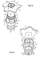
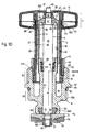
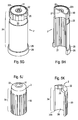
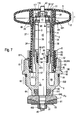
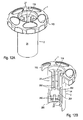
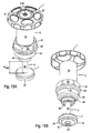
- the upper part consists in principle of a handle 1, the rotational movement of which is transmitted to an outer sleeve 2 , an inner sleeve 3 telescopically received therein - this acts as a driving element - a plunger 4, which projects axially through the inner sleeve 3 and a head piece 6 adjoining thereto.
- a plunger 4 which projects axially through the inner sleeve 3 and a head piece 6 adjoining thereto.
- a valve plate 7 is fixed at the lower end of the plunger 4 .
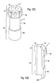
- the upper part is in the zero stroke H 0 so in the fully open position with maximum retracted ram . 4
- the handle 1 is composed of an upper first handle part 11 and a second lower handle part 12 .
- Both gripping parts 11 , 12 have an inner profiling 110, 120, wherein the inner profiling 110 of the first gripping part 11 is non-rotatably engaged with the outer profiling 20 of the outer sleeve 2 and the inner profiling 120 on the second gripping part 12 serves for the second gripping part 12 to protrude over the outer profiling 20 can slide to the level of the radial groove 23 on the outer sleeve 2 (see Figures 5C to 5H).
- the top surface 22 of the outer sleeve 2 is formed as a recess 221 for an insert 222 , which characterizes the guided in the conduit medium - eg hot or cold water.
- a second locking ring 99 is inserted, which has an overhang 991 on its outer circumference, which of the first handle portion 11, below the inner profile 110th existing latching lugs 111 is grasped and thus causes the axial securing of the handle 1 .
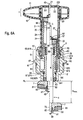
- the plunger 4 Downstream of the central portion 40 , the plunger 4 has an intermediate segment 47 with a flattening 470 and ends with the lower pin 49, which has the external thread 490 for screwing the first nut 91 . Above the first nut 91 is a first disc 93 which holds the valve plate 7 . Between the valve plate 7 and the first disc 93 is the first seal 81, which causes the shut-off of the valve. At the transition from the lower pin 49 to the intermediate segment 47 , the plunger 4 surrounds a second seal 82, which is incorporated in an extension 72 of the valve disk 7 and is held by the first disk 93 .
- the outer sleeve 2 has an inner profiling 27, which extends internally from the lower edge of the collar 26 via the shaft 24 to the level of the radial groove 23 .
- an external profile 30 which is externally on the shaft 34 of the inner sleeve 3 and extends thereon from the lower edge to the vicinity of the collar 32 extends.
- the profilings 27,30 consist of lying between strip-shaped elevations grooves, each extending axially.
- the head piece 6 is initially composed of a lower socket 64 and an upwardly adjoining inner socket 67 , which of an axial passage 69 for receiving the central portion 40 of the plunger 4 are traversed. From the transition between the lower nozzle 64 and the inner nozzle 67 branches off an intermediate piece 63 , to which first a flange 62 and then upwards an upper nozzle 61 connects, the inner socket 67 and the nozzle 63,61 with the flange 62 between them enclose a ring and bag-shaped free space 66 .
- the inner socket 67 has at the upper portion an external thread 68 , which is in engagement with an internal thread 38 of the inner sleeve 3 .
- a seal package is attached, which is the main seal 89 and composed from bottom to top of the following elements: a fifth seal 85, a second disc 94, a sixth seal 86, a third disc 95, wherein a first Circlip 98 is used to fix the seal package.
- the fifth seal 85 as the first element of the main seal 89 is positioned at the inner distance a.
- the inner distance a is obtained as an offset from the lower end of the head piece 6 and the third seal 83 - at least up to the position in which the flow medium above the valve disk 7 may be present on the plunger 4 - in the interior of the upper part to the fifth seal 85 zoom.
- the upper nozzle 61 is provided on the inside with an internal thread 618 which extends down to a lying on the level of the flange 62 annular shoulder 612 on which the collar 26 of the outer sleeve 2 rests. In the closing direction of the valve, the inner sleeve 3 moves into the free space 66 .
- the upper nozzle 61 has an outer profiling 60, preferably in the form of a polygon for attaching a wrench on.
- Below the flange 62 is a radial groove 65, in which a fourth seal 84, preferably an O-ring, is inserted. Below the radial groove 65 extending over the intermediate piece 63 external thread 630 is present.
- the lower nozzle 64 has an inner radial groove 641 for receiving a third seal 83, wherein the radial groove 641 exits downwardly and is upwardly of undercut contour.
- the valve position "fully open” at the zero stroke H 0 presses the top of the valve plate 7 against the underside of the third seal 83 and thus causes a more intense pressing of the third seal 83 in the inner radial groove 641, with the result reinforced sealing. At the same time, this ensures that no dead space remains in this area.
- the retaining ring 5 is used to fix the outer sleeve 2 in the head piece 6.
- the retaining ring 5 has an outer profiling 50 in the upper region - eg a toothing for attaching a ratchet wrench - a flange 52 projecting outwardly below the outer profiling 50 and a flange 52 below the outer profiling 50 existing external thread 58.
- the retaining ring 5 comprises the lower portion of the shaft 24, the flange 52 is seated on the uppermost shoulder on the upper nozzle 61, the external thread 58 is in engagement with the internal thread 618 and the lower edge of the retaining ring 5 presses the shoulder 25 of the outer sleeve 2.
- the retaining ring 5 With its collar 26 on the annular shoulder 612 of the head piece 6 upstanding outer sleeve 2 is positioned.
- the head piece 6 may be a solid or separate part of the valve body.
- the retaining ring 5 could instead of the external thread 58 have locking elements of preferably elastic type, which engage in complementary inner contours internally of the upper nozzle 61 on the head piece 6 .
- the internal thread 618 would be unnecessary on the head piece 6 and yet the outer sleeve 2 axially fixed in the head piece 6 are held.
- the possible modification of the retaining ring 5 with locking elements and the head piece 6 with inner contours instead of mutually complementary threads 58,618 also applies to the second and third variant of the upper part according to FIGS . 6A and 7.
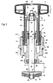
- the previously shown and described upper part is extended to the position "partially open” with the partial stroke H 1 .
- the movement of the upper part is as follows.
- the outer sleeve 2 is also rotated in the right direction, which in turn rotates the inner sleeve 3 .
- the internal thread 38 screwed on further to the external thread 68 of the inner nozzle 67 and this pushes the inner sleeve 3 down deeper with the shaft 34 into the space 66 inside.
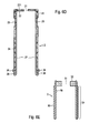
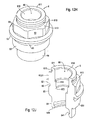
- FIG. 4 shows both end positions H 0 and H max in comparison.
- the outer and inner sleeve 2.3 are taken back in the direction of rotation, the internal thread 38 further screwed onto the external thread 68 and thus the shaft 34 of the inner sleeve 3 even deeper into the free space 66 moved into it. From the downwardly moving inner sleeve 3 , the outer profile 30 slides in the inner profiling 27 of the axially fixed outer sleeve 2.
- the plunger 4 is taken, so that the lower portion of the central portion 40 of the plunger 4 maximum from the lower port 64th of the head piece 6 moves out.
- the first seal 81 carried by the valve disk 7 has moved to the valve seat and completely obstructs the passage opening in the valve.
- the upper pin 43 of the plunger 4 furthest from the through hole 21 of the outer sleeve 2 removed. This indicates that the upper part is not in the "fully open" position.
- the length of the middle section 40 of the ram 4 extending at the maximum stroke H max is smaller than the inside distance a. This avoids that the flow medium exposed, thereby corroded and roughened by deposits surface of the central portion 40 of the plunger 4 during retraction of the upper part in the zero stroke H 0, the main seal 89 damaged.
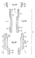
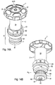
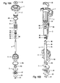
- FIGS. 5A and 5B are identical to FIGS. 5A and 5B.
- the upper part is shown in two different explosive representations and is intended to provide an overview of all associated components.
- the upper part is composed of the following components: the handle 1, consisting of the first and second handle part 11,12, the retaining ring 99, the outer sleeve 2, the second nut 92, the fifth disc 97, the inner sleeve 3, the fourth disc 96, the first locking ring 98, the main seal 89 - consisting of the third disc 95, the sixth seal 86, the second disc 94 and the fifth seal 85 -, the plunger 4, the retaining ring 5, the head piece. 6 , the fourth seal 84, the third seal 83, the valve disk 7, the second seal 82, the first seal 81, the first disk 93, and the first nut 91.
- the first half-shell-shaped handle part 11 with its star-like geometry has a central axial passage 119, which is surrounded by an inner profiling 110 . Alternately ends each second profile web with a deeper down, projecting into the axial passage 119 locking lug 111.
- the locking lugs 111 are located below the Innprofiltechnik 110 and continue over the lower edge of an inner web 112 down. Instead of individual locking lugs 111 , a radially encircling locking member may be present as an annular bead.
- An outer edge web 113 has a discontinuous grooved lower edge 114 which is complementary formed to the upper edge of the second handle portion 12 , is joined together with this form-fitting.
- the second handle part 12 also has centrally an axial passage 129, which is surrounded by an inner profile 120 with profile webs , which surrounds an inner web 122 .
- the outer sleeve 2 has on the upper side a raised, outer peripheral edge, so that a disc-shaped recess 221 is formed, which simultaneously forms the top surface 22 .
- a centrally positioned axial through-hole 21 surrounded by a raised annular region.
- an outer profiling 20 is provided at the upper end, which extends to the radial groove 23 and is intended for positive engagement with the inner profiling 110 of the first handle part 11 .
- the inner profiling 120 on the second grip part 12 allows this grip part 12 to slide over the outer profiling 20 of the outer sleeve 2 into the radial groove 23 .
- External profiling 20 and radial groove 23 have approximately the same height.
- the second grip part 12 rests against the lower edge of the radial groove 23 , on the inner web 122 of the second grip part 12 a second retaining ring 99 is positioned whose overhang 991 is under the gripping lugs 111 of the first grip part 11 .
- a second retaining ring 99 is positioned below the outer sleeve 2 ends after a cylindrical shaft 24 with a thickened outer diameter collar 26, wherein in the transition between shaft 24 and collar 26, a shoulder 25 is formed.
- the outer sleeve 2 has an inner profiling 27, which extends from the lower end to approximately at the radial groove 23 and is formed by axially extending, raised webs and to alternating grooves.
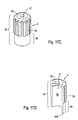
- the inner sleeve 3 has a conically tapered collar 32 , which ends at the top with a plane surface which surrounds an axial through hole 31 .
- On the outer surface of the shaft 34 extends virtually from the lower edge 345 to close to the collar 32 from a raised webs and grooves therebetween existing outer profile 30, which is intended for complementary engagement with the inner profile 27 of the outer sleeve 2 .
- Inwardly owns the shaft 34 of the inner sleeve 3 has an internal thread 38 which engages with the external thread 68 of the head piece 6 .
- FIG. 5L is a diagrammatic representation of FIG. 5L
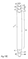
- the elongated plunger 4 consists of a central portion 40 which ends at the top of a first shoulder 44 , from which extends a reduced in diameter first projection 41 to a second shoulder 45 . This is followed by a second, small-diameter extension 42 with an external thread 420 , which terminate at a third shoulder 46 , from which extends an again reduced in diameter upper pin 43 .
- the lower end of the central portion 40 has an undercut 48 which separates an intermediate segment 47 which is provided with a one-sided flattening 470 and has the same shape as the axial passage 79 of the valve disk 7 .
- a lower pin 49 closes with external thread 490 for attachment of the first nut 91 at.
- the lower pin 49 forms the lower end of the plunger . 4
- the retaining ring 5 has a basically cylindrical cross-section and is externally divided by a projecting flange 52 into an upper region with an outer profiling 50 and a lower region with an outer thread 58 .
- the head piece 6 consists of an inner tube portion 67 with an axial passage 69, an upper piece 61, an intermediate connecting piece 63 and a bottom nozzle 64, the inner tube portion 67 extends beyond the upper piece 61 and upper piece 61 with flange 62 and intermediate support 63 to the inner socket 67 with Include distance. The distance results in a ring-shaped and bag-shaped free space 66.
- the inner socket 67 has an external thread 68 on the upper section.
- an inner radial groove 671 is formed near the upper mouth, in which the first retaining ring 98 is received to fix the main seal 89 .
- annular shoulder 672 is formed, on which the fifth seal 85 as the bottom Element of the main seal 89 rests.
- the upper nozzle 61 has on its inside the internal thread 618 and below for placing the collar 26 of the outer sleeve 2 an annular shoulder 612.
- the space 66 extends further below the annular shoulder 612 to the junction of the intermediate nozzle 63 from the transition between the lower nozzle 64 and the inner socket 67.
- the upper nozzle 61 is externally provided with an outer profile 60, here a hexagon.
- the intermediate stub 63 has at the transition to the upper stub 61 a flange 62 and an underlying radial groove 65 for receiving the fourth seal 84.
- the lower stub 64 has in the region of the axial passage 69 an inner Radial groove 641 for embedding the third seal 83 and terminates at the lower edge 645, which surrounds the axial passage 69 circular.
- the third seal 83 has an axial passage 839 for the sliding passage of the central portion 40 of the plunger 4 and an upper portion 831 and a smaller outer portion 832 in the outer diameter , so that at the lower part 832 a cutout 833 results.
- the valve plate 7 has a central axial passage 79 with flats 790 to the top mouth and a profiling 70 on the bottom. At the lower mouth of the axial passage 79 has an extension 72 to store the second seal 82 therein. The extension 72 is bounded by a downwardly raised edge 71 . At the flattenings 790 , the flattenings 470 of the intermediate segment 47 of the plunger 4 come to rest.
- the first seal 81 which is intended for shut-off in the valve, has an axial passage 819 and an upper-side profiling 810, which is designed to be complementary to the profiling 70 on the valve disk 7.
- the axial passage 819 in the first seal 81 serves to receive the raised edge 71 of the valve disk 7.
- FIG. 6A shows the upper part in both end positions H 0 and H max in comparison.
- this is now composed of an outer piece 6 ' and a separate inner socket 67 , which is screwed into the outer piece 6 ' by means of the external thread 675 and the internal thread 642 present in the outer piece 6 ' .
- the internal thread 642 is located in the lower nozzle 64 above the inner radial groove 641.
- the intermediate piece 63 with the external thread 630 joins, followed by the radial groove 65 and then the flange 62 ,
- the inner socket 67 has above the external thread 675 a radial groove 674 for receiving a seventh seal 87, which is in the assembled state between the outer piece 6 ' and the screwed inner socket 67 .
- the radial groove 674 is bounded by a flange 673 , above which the inner socket 67 is first reduced in outside diameter and then expanded again.
- the extended region has an external thread 68, with which the internal thread 38 on the shaft 34 of the inner sleeve 3 is engaged.
- an inner radial groove 671 for receiving the first securing ring 98 is provided below which the annular shoulder 672 lies at a distance.
- the main seal 89 consisting of the sealing package 85, 86, 94, 95, is mounted.
- the collar 26 is now positioned offset from the lower end 28 and, in turn, relies on the annular shoulder 612 of the now two-piece head piece 6, namely in the outer piece 6 ' on.
- the outer sleeve 2 has unchanged at the top of its shaft 24, the outer profiling 20, the through hole 21 in the top surface 22 with the upper side recess 221, the radial groove 23 and the inner profile 27.
- the outer sleeve 6 ' standing outer sleeve 2 is the retaining ring 5, whose outer thread 58 present in the lower part is screwed to the inner thread 618 on the outer piece 6 ' , the flange 52 being seated on the upper edge of the outer piece 6' .
- Unchanged is also on the upper part of the retaining ring 5, the outer profile 50th
- This third part third variant has low structural modifications to the outer and inner sleeve 2,3 , the head piece 6 and the valve plate 7 , wherein the operation and the other components remain unchanged.
- the upper part is in the end position H 0 .
- the head piece 6 has an inclined portion extending from the lower nozzle 64 to the intermediate piece 63 with the external thread 630 , followed by the radial groove 65 and then the flange 62 .
- the head piece 6 ends with the unchanged upper socket 61, which has the outer profiling 60, for example a hexagon, and is provided with the internal thread 618 .
- the inner socket 67 has at the upper end an outwardly extending extension which has the external thread 68 , with which the internal thread 38 on the shaft 34 of the inner sleeve 3 is engaged.
- an inner radial groove including located in the distance from the main seal 89, the annular shoulder 672.
- the main seal 89 consisting of the stack of gaskets 85,86, 94, 95, stored.
- the collar 26 now has an outer radial groove 262, in which the eighth element 88 is inserted, which serves to inhibit the outer sleeve 2 against unintentional rotation, eg due to vibration.
- the lower end of the collar 26 rests on the annular shoulder 612 of the head piece 6 .
- the outer sleeve 2 has unchanged on top of its shaft 24, the outer profiling 20.
- the through hole 116 and the top-side insert 117 are now provided in the top surface 115 of the first handle part 11 .
- the radial groove 23 and the inner profiling 27 are still located on the outer sleeve 2.
- outer sleeve 2 To fix the standing in the head piece 6 outer sleeve 2 is the retaining ring 5, whose present in the lower part of external thread 58 is screwed to the internal thread 618 on the head piece 6 .
- the flange 52 of the retaining ring 5 sits on the upper edge of the head piece 6 .
- the outer profiling 50 on the upper part of the retaining ring 5 remains unchanged.
- On the inner sleeve 3 of the collar 32 is modified - now just - but also on the shaft 34, the outer profile 30 and the internal thread 38 and the through hole 31 on the collar 32.
- the outer profile 30 extends only over a central region of the shaft 34.
- the first seal 81 is provided, which causes the shut-off of the valve and reaches up to the lower pin 49 , so that here the second seal 82 of Figure 2 is omitted.
- a first nut 91 is screwed against the first disc 93 on the external thread 490 at the lower pin 49 .
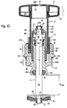
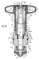
- This pair of figures shows an upper fourth variant in the end position H 0 with constructive differences on the outer and inner sleeve 2,3, the head piece 6, and a slight change to the valve disc 7.
- an intermediate sleeve 5 ' modifies the Function and a smaller dimension of the valve bonnet can be realized with extended construction for special applications.
- the head piece 6 is composed first of the lower nozzle 64 and an upwardly adjoining inner socket 67 , which are traversed by an axial passage 69 for receiving the central portion 40 of the plunger 4 .
- the intermediate piece 63 closes with the external thread 630 , followed by the radial groove 65 and then the flange 62 .
- the upper nozzle 61 which has the outer profiling 60 - here, for example, a hexagonal profile - ends the head piece 6, wherein the opposite inner side with an internal thread 618 is provided.
- the internal thread 618 extends downwards above an annular shoulder 612 lying at the level of the flange 62 and engages with the external thread 58 'of the intermediate sleeve 5' .
- the intermediate sleeve 5 ' has, subsequent to the external thread 58', a radial groove 51 ', in which an eighth element 88 for inhibiting the outer sleeve 2 against inadvertent rotation, eg due to vibration, is inserted.
- there is a radial groove 57 ' which receives the pin end of the co-rotating locking element 29 that is at the front when the handle 1 rotates, which additionally secures the intermediate sleeve 5 against axial displacement.
- the main seal 89 between the first annular shoulder 672 and the first retaining ring 98 ', on which the intermediate sleeve 5' rests and which rests on the annular shoulder 612 is arranged.
- the main seal 89 is composed of the sealing package with the individual components 85, 86 , 94, 95 .
- the first element of the main seal 89 is the fifth seal 85, which is positioned with the inner distance a.
- the inner distance a is obtained as an offset from the lower end of the head piece 6 and the third seal 83 - at least up to the position in which the flow medium above the valve disk 7 may be present on the plunger 4 - in the interior of the upper part to the fifth seal 85 zoom.
- the outer sleeve 2 is provided on the collar 26 with preferably two 180 ° opposite flat depressions 261 , from which in each case a through hole 260 extends in the radial direction and as a radial groove 57 ' in the intermediate sleeve 5' continues.
- the outer sleeve 2 is seated axially on the annular surface 611 on the upper port 61 of the head piece 6 and has unchanged at the top of its shaft 24, the outer profile 20 and the radial groove 23.
- the through hole 21 and the top side liner 222 are located in the top surface 115 of the first handle part 11.
- the inner profiling 27 extends above the collar 26, from the upper end of the intermediate sleeve 5 ' via the shaft 24 to the opposite end.
- the inner profiling 27 of the outer sleeve 2 engages an outer profile 30 , which is externally on a flared collar 32 in continuation of the shaft 34 of the inner sleeve 3 is present and coaxial with External thread 39 is located, which 'is in engagement with the internal thread 59' of the intermediate sleeve 5 , wherein between outer profile 30 and external thread 39 is an externally smooth section of the shaft 34 itself.
- the profilings 27,30 consist of lying between strip-shaped elevations grooves, each extending axially. Alternatively, the intermediate sleeve 5 'be integrally connected to the head piece 6 .
- the collar 32 on the inner sleeve 3 has an upwardly open, extended mouth 33, which continues axially from the through hole 31 .
- a second nut 92 and a fifth disc 97 are positioned within the mouth 33 , which define the inner sleeve 3 fixed in the axial direction, but radially rotatable between the first shoulder 44 and the second shoulder 45 .
- the peculiarity of the upper part in the fifth variant consists first in that handle 1 and outer sleeve 2 form a common part, after which extends from the underside of the handle 1 of the sleeve-shaped shaft 24 of the outer sleeve 2 .
- this upper part also consists of a head piece 6 with the upper stub 61, the outer profile 60 located thereon , the adjoining flange 62, the intermediate stub 63, the lower stub 64, the valve plate 7, under which the first seal 81 is disposed, and the lower closing parts with the first disc 93 and the screwed onto the lower pin 49 of the plunger 4 first nut 91.
- the outer radial groove 65 in which the fourth seal 84 is embedded and for the sealing of the in the Valve body used upper part provides.
- the upper part is in the zero stroke H 0 , ie in the fully open position with maximum retracted ram 4, indicated by the upper pin 43 of the plunger 4 emerging from the top surface 22 through the through hole 21 of the handle 1 .
- the lower region of the middle section 40 of the plunger 4 protrudes from the lower connection 64, in which the third seal 83 enveloping the middle section 40 is inserted.
- the adjustment range also slightly removed from the maximum stroke H max is indicated by the upper pin 43 of the plunger 4 sunk in the cover surface 22 in the through hole 21 of the handle 1 .
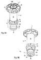
- the upper part according to the fifth variant is shown in two different explosive representations as a complete overview of all associated components.
- it initially consists of the handle 1, in which the cover surface 22 can be inserted from above and which is integrally connected to the outer sleeve 2, which is formed essentially by the shaft 24 .
- the top surface 22 may be provided as an insert with identifier for hot or cold water.
- an eighth element 88 as anti-rotation, a retaining ring 92, a fifth disc 97, the inner sleeve 3 as a driving element, an intermediate sleeve 5 ', the main seal 89 - consisting of the sixth seal 86, second disc 94 and fifth seal 85 , the plunger 4, the head piece 6, the fourth seal 84, the third seal 83, the valve disk 7, the first seal 81, the first disk 93 and the first nut 91.
- the dish-shaped handle 1 opens centrally the circular axial passage 119, in which the cover surface 22 can be inserted from above. From the axial passage 119 radially ribs extend into the outer area and go into a downwardly directed edge web 113 on. To the underside of the handle 1 , the downwardly directed sleeve-shaped shaft 24 sets in, which has an inwardly directed central web 291 , from which parallel spaced from the shaft 24 , upper tongues 292 and elastically bendable lower tongues 290 extend, the latter inwardly directed, have hook-shaped locking elements 29 .
- the inner profiling 27 On the inner wall of the shaft 24 is the inner profiling 27, which is formed by star-shaped ribs 27 extending from the central web 291 to close to the mouth of the axial passage 119 in the handle 1 , so that the inserted top surface 22 on the plurality of Ridges 27 is supported.
- the shank 24 ends with the lower edge 295 , wherein the ring of articulating elements 29 - encased by the shank 24 - is located above the lower edge 295 .
- designed as an inner sleeve entrainment element 3 has a zuoberst final collar 32, which is in principle a horizontal plane surface, which surrounds the axial through hole 31 .
- An external profiling 30 configured as a longitudinal toothing is located on the head 37, from the underside of which the shank 34 continues axially with a reduced diameter, wherein the lower end of the shank 34 is thickened again in diameter and has the external thread 39 .
- the portion of the shaft 34 lying between the head 37 and the external thread 39 has a free cut 35 reducing the outside diameter .
- the through hole 31 extends axially through the entire carrier element 3, so that it emerges on the one hand within the collar 32 and on the other hand from the bottom edge 345 of the carrier element 3 .
- the plunger 4 is essentially a cylindrical axle bar with areas of different diameters and starts with a relatively short upper pin 43, of which adjoins a third shoulder 46, a diameter-thickened second extension 42 . Close below the third shoulder 46 is an annular groove 421.
- the first projection 41 which has a slightly reduced diameter, sets against the second extension 42 and ends with a thickening 410 in front of the first shoulder 44 .
- Below the shoulder 44 is the again thickened and relatively long central portion 40, the first an intermediate segment 47, then a sealing segment 471 and then a lower pin 49 follow.
- the following segments 47,471,49 are each reduced in diameter, wherein the lower pin 49, the external thread 490 has.
- the substantially cylindrical intermediate sleeve 5 ' has at the head part an outer profiling 50', for example a hexagon, and in the lower area an external thread 58 ' above which the radial groove 57' is located. Between the outer profiling 50 ' and the radial groove 57' is a cylindrical portion 55 ' and below the external thread 58' closes the intermediate sleeve 5 ' with an outer diameter reduced end segment 56' from. From above to below the radial groove 57 ' passes through the intermediate sleeve 5' serving as a feed thread internal thread 59 ', which ends at an inner Freistrich 54' , which an inwardly directed collar 53 ' follows.
- the one-piece head piece 6 with the axial passage 69 is divided into an upper nozzle 61, an enlarged outer diameter flange 62, a reducedrichdruchmesser stub 63 and the further reduced lower nozzle 64.
- Below the shoulder 613 of the upper nozzle 61 is provided with an external profile 60, for example a hexagon.
- the intermediate support 63 to the flange 62 is the outer radial groove 65, and the intermediate support 63 has the external thread 630th
- the axial passage 69 begins within the annular surface 611 opening the female thread 618, which continues up to the first annular shoulder 612 , which is approximately at the height level of the flange 62 .
- the second annular shoulder 672 and near the lower edge 645 is the inner radial groove 641.
- the annular shoulders 612,672 reduces the inner diameter of the axial passage 69th
- the disc-like valve plate 7 in principle has a central axial passage 79 and a substantially horizontal, plan-shaped top.
- a profiling 70 is provided, which consists for example of several radially encircling saw teeth.
- a second disc 94 is inserted, on which the sixth seal 86 rests, which adjoins the lower end of the intermediate sleeve 5 ' .
- the external thread 39 on the shaft 34 of the driving element 3 and the internal thread 59 'of the intermediate sleeve 5' are engaged with each other.
- the inner profiling 27 of the outer sleeve 2 has with the outer profile 30 of the driving element 3 positive connection.
- the plunger 4 which penetrates with its central portion 40, the skin seal 89 and carries at its intermediate segment 47 and lower pin 49, the valve plate 7 with the first seal 81 .
- the intermediate segment 47 is inserted in the axial passage 79 of the valve disk 7, against the underside of the first seal 81 is attached, wherein the sealing segment 471 of the plunger 4 extends through the seal 81 .
- the first disc 93 is placed, which is secured by means of the screwed onto the external thread 490 of the lower pin 49 first nut 91 .
- the third seal 83 is embedded, which includes the central portion 40 , wherein in the present state, the otherwise protruding lower portion of the third seal 83 is pushed from the top of the valve disc 7 maximum in the inner radial groove 641 . From the level of the lower edge 645 to the beginning of the main seal 89 , the inner distance a is again given.
- the external thread 630 on the intermediate stub 63 serves to connect to a complementary internal thread in the valve body, on which the flange 62 comes to rest with sealing by the fourth seal 84 lying in the outer radial groove 65 .
- the outer profiling 60 is provided on the upper stub 61 .
- the annular element 88 inserted in the radial groove 610 acts in frictional engagement with the inner surface of the shaft 24 .
- the lower edge 345 of the driving element 3 sits on the first shoulder 44 of the plunger 4.
- the fifth disc 97 is placed, which is held down with a securing element 92 which engages in the annular groove 421 .
- the first extension 41 comes to lie in the region of the cutout 35
- the second extension 42 projects through the entrainment element 3 in the region of the head 37 .
- the upper pin 43 protrudes from the through hole 21 of the top into the axial passage 119th inserted top surface 22 and thus signals optically and tactile a position of the upper part at least near the zero stroke H 0 .
- the maximum possible stroke H max is preferably by striking the lower edge 345 on the collar 53' and / or the placement of the head 37 the top of the intermediate sleeve 5 ' limited, but dimensioned so that a complete closure of the valve is achieved.
- the third seal 83 may bulge beyond the bottom edge 645 .
- the upper pin 43 retreats into the interior of the upper part, from which it can be seen that the zero-stroke position H 0 has been left.
- the plunger 4 is arranged in the upper part, that this no longer rotates, at least in the immediate vicinity of the maximum stroke H max , ie when placing the first seal 81 on the valve seat and exceeding a defined frictional resistance, but only more carries out the remaining axial movement.
- the length of the middle section 40 of the ram 4 extending at the maximum stroke H max is shorter than the inside distance a. This precludes the surface of the middle section 40 exposed to the flow medium from damaging the main seal 89 when returning to the zero stroke H 0 .
- the maximum possible movement in the zero stroke H 0 is dimensioned so that the top of the valve disc 7 displaces the bulge of the third seal 83 and avoids each cavity so as to leave no gaps as dead space for the formation of impurities.
- the upward moving driver element drags 3, whose top abuts against the composite of the fifth wheel 97 and securing member 52, the plunger 4 with up.
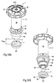
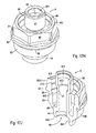
- the sixth variant of the upper part shown here differs externally, apart from the dimensions, barely from its fifth variant.
- Handle 1 and outer sleeve 2 in turn form a common part, after which the sleeve-shaped shaft 24 of the outer sleeve 2 goes off from the underside of the handle 1 .
- this upper part consists of a head piece 6 with the upper nozzle 61 with the outer profile 60, the following flange 62, the intermediate piece 63, the lower nozzle 64, a valve disc 7, the first seal disposed thereon 81, and the lower parts with first disc 93 and the screwed onto the lower pin 49 of the plunger 4 first nut 91.
- FIGS. 15A and 15B are identical to FIGS. 15A and 15B.
- the upper part of the sixth variant consists in the sequence from top to bottom, first of the handle 1 with the cover surface 22 can be inserted from above and extending from the bottom of the handle 1 outer sleeve 2, which has as essential the shaft 24 , wherein handle 1 and Form outer sleeve 2 a piece.
- the upper part also has an eighth element 88 as anti-rotation, a second nut 92 as a securing element, a fifth disc 97, the driving element 3, the main seal 89 - with the sixth seal 86, second disc 94 and fifth seal 85 - , the plunger 4, the Head piece 6, the fourth seal 84, the third seal 83, the valve plate 7, the first seal 81, the first disc 93 and the first nut 91.
- the circular axial passage 119 emerges centrally, into which the top surface 22 can be inserted from above.
- Radial ribs extend from the axial passage 119 into the outer area in the form of spokes and merge into the downwardly directed edge web 113 .
- the downwardly facing outer sleeve 2 goes off with the shaft 24 , which has an annular groove 293 in the lower third, which is bounded below by a collar 294 .
- From the collar 294 extends a plurality of axially directed lower tongues 290 which form a collar and are elastically movable through spaces.
- each tongue 290 has an outwardly oriented locking element 29 of hook-like cross-section.
- the inner sleeve 3 has a conically tapered collar 32 with an upper planar surface, which surrounds a central through hole 31 .
- On the outer surface of the shaft 34 of the inner sleeve 3 extends from the collar 32 to an open space 36, the webs and intermediate grooves outer profile 30, wherein the free surface 36 is reduced in outer diameter and extends approximately over the lower third of the shaft 34 .
- the shaft 34 terminates at the end opposite the collar 32 with the lower edge 345 .
- On the inner wall of the shaft 34 is the internal thread 38th
- the rod-shaped plunger 4 has a relatively long central portion 40, which ends at the top of a first shoulder 44 , from which extends a reduced in diameter first projection 41 to a second shoulder 45 . This is followed by a second, smaller diameter extension 42 with an external thread 420 , which terminate at a third shoulder 46 , from which a renewed in diameter reduced upper pin 43 extends. Down to the middle section 40 , an intermediate segment 47, then a sealing segment 471 and finally a lower pin 49 closes at the bottom. In relation to the middle section 40 , the following segments 47,471,49 each have a reduced diameter, wherein the lower pin 49 has the external thread 490 .
- the plunger 4 is preferably made of chrome steel and has a round cross-section.
- the driving element 3 is with its internal thread 38 with the external thread 68 of the inner nozzle 67 of the head piece 6 in engagement.
- the shaft 24 of the outer sleeve 2 is inserted with the handle 1 arranged thereon above.
- the outer profile 30 of the driving element 3 and the inner profiling 27 in the shaft 24 with each other in a rotationally fixed engagement and the locking elements 29 are hooked into the inner radial groove 650 on the head piece 6 , so that handle 1 with outer sleeve 2 can rotate on the head piece 6 , but axially fixed.
- the space 66 between the lower tongues 290 and the outer wall of the inner nozzle 67 allows the elastic inward bending of the lower tongues 290 during the attachment and removal of the outer sleeve 2 on the head piece 6.
- the Antirotations rejoin is in the annular groove 293 element 88, which with the Inner wall of the upper nozzle 61 has frictional engagement.
- the package assembly of the main seal 89 - consisting of the fifth seal 85, second disc 94 and sixth seal 86 - which rests on the second annular shoulder 672 is held down by a basically basket-shaped securing element 98 , wherein the upper segment in the inner, undercut radial groove 671 supported.
- Headpiece 6 and driving element 3 are axially penetrated by the plunger 4 , which is fixed axially fixed on the driving element 3 .
- the plunger 4 which is fixed axially fixed on the driving element 3 .
- the first extension 41 of the plunger 4 comes to lie in the through hole 31 and the upper pin 43 protrudes at the zero stroke H 0 from the through hole 21 of the top surface 22 out.
- the downwardly moving carrier element 3 pulls the axially fixed on the collar 32 ram 4 successively from the head piece 6 out until the maximum stroke H max would be reached.
- the locking elements 29 slide in the inner radial groove 650.
- the maximum possible stroke H max is preferably limited by the abutment of the upper edge of the inner nozzle 67 from below against the collar 32 and / or the placement of the lower edge 345 at the bottom of the free space 66 , but dimensioned so that a complete closure of the valve is achieved.
- the driving element 3 screws upwards and pulls the plunger 4 in the same direction.
Landscapes
- Engineering & Computer Science (AREA)
- General Engineering & Computer Science (AREA)
- Mechanical Engineering (AREA)
- Mechanically-Actuated Valves (AREA)
- Lift Valve (AREA)
- Taps Or Cocks (AREA)
- Sliding Valves (AREA)
- External Artificial Organs (AREA)
- Feeding And Controlling Fuel (AREA)
- Pens And Brushes (AREA)
Priority Applications (1)
| Application Number | Priority Date | Filing Date | Title |
|---|---|---|---|
| EP06405014A EP1715232B1 (fr) | 2005-04-20 | 2006-01-13 | Valve avec une partie supérieure à utiliser dans un logement de soupape |
Applications Claiming Priority (2)
| Application Number | Priority Date | Filing Date | Title |
|---|---|---|---|
| EP05405303A EP1715231A1 (fr) | 2005-04-20 | 2005-04-20 | Valve avec une partie supérieure à utiliser dans un logement de soupape |
| EP06405014A EP1715232B1 (fr) | 2005-04-20 | 2006-01-13 | Valve avec une partie supérieure à utiliser dans un logement de soupape |
Publications (3)
| Publication Number | Publication Date |
|---|---|
| EP1715232A2 true EP1715232A2 (fr) | 2006-10-25 |
| EP1715232A3 EP1715232A3 (fr) | 2007-03-14 |
| EP1715232B1 EP1715232B1 (fr) | 2008-03-26 |
Family
ID=34942969
Family Applications (2)
| Application Number | Title | Priority Date | Filing Date |
|---|---|---|---|
| EP05405303A Withdrawn EP1715231A1 (fr) | 2005-04-20 | 2005-04-20 | Valve avec une partie supérieure à utiliser dans un logement de soupape |
| EP06405014A Expired - Lifetime EP1715232B1 (fr) | 2005-04-20 | 2006-01-13 | Valve avec une partie supérieure à utiliser dans un logement de soupape |
Family Applications Before (1)
| Application Number | Title | Priority Date | Filing Date |
|---|---|---|---|
| EP05405303A Withdrawn EP1715231A1 (fr) | 2005-04-20 | 2005-04-20 | Valve avec une partie supérieure à utiliser dans un logement de soupape |
Country Status (3)
| Country | Link |
|---|---|
| EP (2) | EP1715231A1 (fr) |
| AT (1) | ATE390589T1 (fr) |
| DE (1) | DE502006000505D1 (fr) |
Families Citing this family (9)
| Publication number | Priority date | Publication date | Assignee | Title |
|---|---|---|---|---|
| US7934520B2 (en) | 2007-05-08 | 2011-05-03 | Kohler Co. | Coupling assembly for plumbing fitting |
| WO2012045310A1 (fr) * | 2010-10-06 | 2012-04-12 | Danfoss A/S | Soupape de régulation de débit et procédé d'assemblage d'une soupape de régulation de débit |
| EP2447582B1 (fr) * | 2010-10-29 | 2012-10-10 | Seppelfricke Armaturen GmbH | Partie supérieure de soupape d'une armature d'eau potable |
| EP2957801A1 (fr) * | 2014-06-18 | 2015-12-23 | Far Rubinetterie S.P.A. | Soupape hydraulique pouvant être prédéfinie, en particulier pour des conduites hydrauliques d'usine thermique |
| JP6756702B2 (ja) | 2014-09-01 | 2020-09-16 | ダンフォス アクチ−セルスカブ | 溶接されたバルブハウジングを有するバルブ |
| EP3070380B1 (fr) | 2015-03-19 | 2019-06-26 | R. Nussbaum AG | Actionneur de vanne |
| CN110332325A (zh) * | 2019-07-22 | 2019-10-15 | 上海益鼎石化设备制造有限公司 | 一种气控紧急泄放阀 |
| CN115384947B (zh) * | 2022-10-08 | 2023-11-21 | 航天特种材料及工艺技术研究所 | 一种放气阀及气密包装箱 |
| CN118500587A (zh) * | 2024-04-19 | 2024-08-16 | 基康仪器股份有限公司 | 一种带自补压功能的钻孔应力计 |
Citations (4)
| Publication number | Priority date | Publication date | Assignee | Title |
|---|---|---|---|---|
| RU2100678C1 (ru) | 1992-01-08 | 1997-12-27 | Надежда Федоровна Чутчева | Вентиль |
| DE19705982C1 (de) | 1997-02-17 | 1998-08-06 | Seppelfricke Armaturen Gmbh & | Ventiloberteil |
| AT405440B (de) | 1996-04-10 | 1999-08-25 | Bwt Ag | Ventil |
| DE10225101A1 (de) | 2002-06-05 | 2003-12-24 | Seppelfricke Armaturen Gmbh & | Ventil-Oberteil und zugehöriger Handgriff |
Family Cites Families (4)
| Publication number | Priority date | Publication date | Assignee | Title |
|---|---|---|---|---|
| DE739519C (de) * | 1941-01-09 | 1943-09-28 | Schaeffer & Budenberg G M B H | Schnellschlussventil |
| US3409271A (en) * | 1966-05-04 | 1968-11-05 | Ideal Aerosmith Inc | Fluid flow control valve |
| US4063707A (en) * | 1976-01-23 | 1977-12-20 | Philadelphia Gear Corporation | Valve protective mechanism for power operated valves |
| DE19840128A1 (de) * | 1998-09-03 | 2000-04-13 | Heimeier Gmbh Metall Theodor | Ventiloberteile für Handregulierventile insbesondere für Heizungsanlagen |
-
2005
- 2005-04-20 EP EP05405303A patent/EP1715231A1/fr not_active Withdrawn
-
2006
- 2006-01-13 DE DE502006000505T patent/DE502006000505D1/de not_active Expired - Lifetime
- 2006-01-13 EP EP06405014A patent/EP1715232B1/fr not_active Expired - Lifetime
- 2006-01-13 AT AT06405014T patent/ATE390589T1/de not_active IP Right Cessation
Patent Citations (4)
| Publication number | Priority date | Publication date | Assignee | Title |
|---|---|---|---|---|
| RU2100678C1 (ru) | 1992-01-08 | 1997-12-27 | Надежда Федоровна Чутчева | Вентиль |
| AT405440B (de) | 1996-04-10 | 1999-08-25 | Bwt Ag | Ventil |
| DE19705982C1 (de) | 1997-02-17 | 1998-08-06 | Seppelfricke Armaturen Gmbh & | Ventiloberteil |
| DE10225101A1 (de) | 2002-06-05 | 2003-12-24 | Seppelfricke Armaturen Gmbh & | Ventil-Oberteil und zugehöriger Handgriff |
Also Published As
| Publication number | Publication date |
|---|---|
| ATE390589T1 (de) | 2008-04-15 |
| EP1715232A3 (fr) | 2007-03-14 |
| EP1715231A1 (fr) | 2006-10-25 |
| DE502006000505D1 (de) | 2008-05-08 |
| EP1715232B1 (fr) | 2008-03-26 |
Similar Documents
| Publication | Publication Date | Title |
|---|---|---|
| DE69930849T2 (de) | Ventil mit grossem durchfluss | |
| EP3221621B1 (fr) | Partie supérieure de soupape | |
| EP2522887B1 (fr) | Partie supérieure de soupape | |
| EP1715232B1 (fr) | Valve avec une partie supérieure à utiliser dans un logement de soupape | |
| DE202014101096U1 (de) | Ventiloberteil | |
| AT509361B1 (de) | Spindellagerung | |
| DE69220415T2 (de) | Wartungseinrichtung für Ventile | |
| DE19510169A1 (de) | Futter mit Kupplung | |
| DE102011056767B3 (de) | Sicherheitsventil | |
| DE102007044659B4 (de) | Zweiteiliges Ventilgehäuse eines Tiertränkeventils | |
| DE102011056758B4 (de) | Sicherheitsventil | |
| DE102013101677B4 (de) | Sicherheitsventil | |
| EP3591271B1 (fr) | Partie supérieure de soupape | |
| DE102018213712B4 (de) | Ventilanordnung | |
| DE10106382B4 (de) | Thermostatkopf für Ventile von Warmwasser-Heizkörpern | |
| EP3199855A1 (fr) | Corps d'accouplement pour un raccord enfichable amovible d'une conduite | |
| WO2019174903A1 (fr) | Robinet sanitaire | |
| DE2924372C3 (de) | Ventil, insbesondere thermostatisch gesteuertes Heizkörperventil mit Voreinstellung | |
| DE102011056763B3 (de) | Sicherheitsventil | |
| EP2696117B1 (fr) | Partie supérieure de soupape | |
| DE102011056753B4 (de) | Sicherheitsventil | |
| EP2447582B1 (fr) | Partie supérieure de soupape d'une armature d'eau potable | |
| EP1503123B1 (fr) | Partie supérieure de soupape | |
| EP1909004B1 (fr) | Soupape de vidange | |
| DE20303978U1 (de) | Schraubelement mit wenigstens einem Betätigungsteil |
Legal Events
| Date | Code | Title | Description |
|---|---|---|---|
| PUAI | Public reference made under article 153(3) epc to a published international application that has entered the european phase |
Free format text: ORIGINAL CODE: 0009012 |
|
| AK | Designated contracting states |
Kind code of ref document: A2 Designated state(s): AT BE BG CH CY CZ DE DK EE ES FI FR GB GR HU IE IS IT LI LT LU LV MC NL PL PT RO SE SI SK TR |
|
| AX | Request for extension of the european patent |
Extension state: AL BA HR MK YU |
|
| PUAL | Search report despatched |
Free format text: ORIGINAL CODE: 0009013 |
|
| AK | Designated contracting states |
Kind code of ref document: A3 Designated state(s): AT BE BG CH CY CZ DE DK EE ES FI FR GB GR HU IE IS IT LI LT LU LV MC NL PL PT RO SE SI SK TR |
|
| AX | Request for extension of the european patent |
Extension state: AL BA HR MK YU |
|
| 17P | Request for examination filed |
Effective date: 20070315 |
|
| AKX | Designation fees paid |
Designated state(s): AT BE BG CH CY CZ DE DK EE ES FI FR GB GR HU IE IS IT LI LT LU LV MC NL PL PT RO SE SI SK TR |
|
| GRAP | Despatch of communication of intention to grant a patent |
Free format text: ORIGINAL CODE: EPIDOSNIGR1 |
|
| GRAS | Grant fee paid |
Free format text: ORIGINAL CODE: EPIDOSNIGR3 |
|
| GRAA | (expected) grant |
Free format text: ORIGINAL CODE: 0009210 |
|
| AK | Designated contracting states |
Kind code of ref document: B1 Designated state(s): AT BE BG CH CY CZ DE DK EE ES FI FR GB GR HU IE IS IT LI LT LU LV MC NL PL PT RO SE SI SK TR |
|
| REG | Reference to a national code |
Ref country code: GB Ref legal event code: FG4D Free format text: NOT ENGLISH |
|
| REG | Reference to a national code |
Ref country code: IE Ref legal event code: FG4D Free format text: LANGUAGE OF EP DOCUMENT: GERMAN Ref country code: CH Ref legal event code: EP |
|
| REF | Corresponds to: |
Ref document number: 502006000505 Country of ref document: DE Date of ref document: 20080508 Kind code of ref document: P |
|
| REG | Reference to a national code |
Ref country code: CH Ref legal event code: NV Representative=s name: DR. GERHARD ULLRICH |
|
| PG25 | Lapsed in a contracting state [announced via postgrant information from national office to epo] |
Ref country code: FI Free format text: LAPSE BECAUSE OF FAILURE TO SUBMIT A TRANSLATION OF THE DESCRIPTION OR TO PAY THE FEE WITHIN THE PRESCRIBED TIME-LIMIT Effective date: 20080326 |
|
| NLV1 | Nl: lapsed or annulled due to failure to fulfill the requirements of art. 29p and 29m of the patents act | ||
| PG25 | Lapsed in a contracting state [announced via postgrant information from national office to epo] |
Ref country code: LV Free format text: LAPSE BECAUSE OF FAILURE TO SUBMIT A TRANSLATION OF THE DESCRIPTION OR TO PAY THE FEE WITHIN THE PRESCRIBED TIME-LIMIT Effective date: 20080326 Ref country code: SI Free format text: LAPSE BECAUSE OF FAILURE TO SUBMIT A TRANSLATION OF THE DESCRIPTION OR TO PAY THE FEE WITHIN THE PRESCRIBED TIME-LIMIT Effective date: 20080326 Ref country code: PL Free format text: LAPSE BECAUSE OF FAILURE TO SUBMIT A TRANSLATION OF THE DESCRIPTION OR TO PAY THE FEE WITHIN THE PRESCRIBED TIME-LIMIT Effective date: 20080326 |
|
| REG | Reference to a national code |
Ref country code: IE Ref legal event code: FD4D |
|
| PG25 | Lapsed in a contracting state [announced via postgrant information from national office to epo] |
Ref country code: ES Free format text: LAPSE BECAUSE OF FAILURE TO SUBMIT A TRANSLATION OF THE DESCRIPTION OR TO PAY THE FEE WITHIN THE PRESCRIBED TIME-LIMIT Effective date: 20080707 Ref country code: SK Free format text: LAPSE BECAUSE OF FAILURE TO SUBMIT A TRANSLATION OF THE DESCRIPTION OR TO PAY THE FEE WITHIN THE PRESCRIBED TIME-LIMIT Effective date: 20080326 Ref country code: CZ Free format text: LAPSE BECAUSE OF FAILURE TO SUBMIT A TRANSLATION OF THE DESCRIPTION OR TO PAY THE FEE WITHIN THE PRESCRIBED TIME-LIMIT Effective date: 20080326 Ref country code: SE Free format text: LAPSE BECAUSE OF FAILURE TO SUBMIT A TRANSLATION OF THE DESCRIPTION OR TO PAY THE FEE WITHIN THE PRESCRIBED TIME-LIMIT Effective date: 20080626 Ref country code: PT Free format text: LAPSE BECAUSE OF FAILURE TO SUBMIT A TRANSLATION OF THE DESCRIPTION OR TO PAY THE FEE WITHIN THE PRESCRIBED TIME-LIMIT Effective date: 20080901 |
|
| PG25 | Lapsed in a contracting state [announced via postgrant information from national office to epo] |
Ref country code: NL Free format text: LAPSE BECAUSE OF FAILURE TO SUBMIT A TRANSLATION OF THE DESCRIPTION OR TO PAY THE FEE WITHIN THE PRESCRIBED TIME-LIMIT Effective date: 20080326 Ref country code: RO Free format text: LAPSE BECAUSE OF FAILURE TO SUBMIT A TRANSLATION OF THE DESCRIPTION OR TO PAY THE FEE WITHIN THE PRESCRIBED TIME-LIMIT Effective date: 20080326 |
|
| PG25 | Lapsed in a contracting state [announced via postgrant information from national office to epo] |
Ref country code: IS Free format text: LAPSE BECAUSE OF FAILURE TO SUBMIT A TRANSLATION OF THE DESCRIPTION OR TO PAY THE FEE WITHIN THE PRESCRIBED TIME-LIMIT Effective date: 20080726 |
|
| EN | Fr: translation not filed | ||
| PG25 | Lapsed in a contracting state [announced via postgrant information from national office to epo] |
Ref country code: DK Free format text: LAPSE BECAUSE OF FAILURE TO SUBMIT A TRANSLATION OF THE DESCRIPTION OR TO PAY THE FEE WITHIN THE PRESCRIBED TIME-LIMIT Effective date: 20080326 Ref country code: IE Free format text: LAPSE BECAUSE OF FAILURE TO SUBMIT A TRANSLATION OF THE DESCRIPTION OR TO PAY THE FEE WITHIN THE PRESCRIBED TIME-LIMIT Effective date: 20080326 Ref country code: LT Free format text: LAPSE BECAUSE OF FAILURE TO SUBMIT A TRANSLATION OF THE DESCRIPTION OR TO PAY THE FEE WITHIN THE PRESCRIBED TIME-LIMIT Effective date: 20080326 |
|
| PLBE | No opposition filed within time limit |
Free format text: ORIGINAL CODE: 0009261 |
|
| STAA | Information on the status of an ep patent application or granted ep patent |
Free format text: STATUS: NO OPPOSITION FILED WITHIN TIME LIMIT |
|
| 26N | No opposition filed |
Effective date: 20081230 |
|
| PG25 | Lapsed in a contracting state [announced via postgrant information from national office to epo] |
Ref country code: BG Free format text: LAPSE BECAUSE OF FAILURE TO SUBMIT A TRANSLATION OF THE DESCRIPTION OR TO PAY THE FEE WITHIN THE PRESCRIBED TIME-LIMIT Effective date: 20080626 Ref country code: FR Free format text: LAPSE BECAUSE OF FAILURE TO SUBMIT A TRANSLATION OF THE DESCRIPTION OR TO PAY THE FEE WITHIN THE PRESCRIBED TIME-LIMIT Effective date: 20090116 Ref country code: EE Free format text: LAPSE BECAUSE OF FAILURE TO SUBMIT A TRANSLATION OF THE DESCRIPTION OR TO PAY THE FEE WITHIN THE PRESCRIBED TIME-LIMIT Effective date: 20080326 |
|
| PG25 | Lapsed in a contracting state [announced via postgrant information from national office to epo] |
Ref country code: MC Free format text: LAPSE BECAUSE OF NON-PAYMENT OF DUE FEES Effective date: 20090131 Ref country code: IT Free format text: LAPSE BECAUSE OF FAILURE TO SUBMIT A TRANSLATION OF THE DESCRIPTION OR TO PAY THE FEE WITHIN THE PRESCRIBED TIME-LIMIT Effective date: 20080326 |
|
| PG25 | Lapsed in a contracting state [announced via postgrant information from national office to epo] |
Ref country code: CY Free format text: LAPSE BECAUSE OF FAILURE TO SUBMIT A TRANSLATION OF THE DESCRIPTION OR TO PAY THE FEE WITHIN THE PRESCRIBED TIME-LIMIT Effective date: 20080326 |
|
| REG | Reference to a national code |
Ref country code: CH Ref legal event code: PFA Owner name: GEORG FISCHER JRG AG Free format text: JRG GUNZENHAUSER AG#HAUPTSTRASSE 130#4450 SISSACH (CH) -TRANSFER TO- GEORG FISCHER JRG AG#HAUPTSTRASSE 130#4450 SISSACH (CH) Ref country code: CH Ref legal event code: NV Representative=s name: DR. WOLFGANG WEISS GEORG FISCHER AG DIENSTZWEIG PA |
|
| PG25 | Lapsed in a contracting state [announced via postgrant information from national office to epo] |
Ref country code: BE Free format text: LAPSE BECAUSE OF NON-PAYMENT OF DUE FEES Effective date: 20090131 |
|
| PG25 | Lapsed in a contracting state [announced via postgrant information from national office to epo] |
Ref country code: AT Free format text: LAPSE BECAUSE OF NON-PAYMENT OF DUE FEES Effective date: 20090113 |
|
| GBPC | Gb: european patent ceased through non-payment of renewal fee |
Effective date: 20100113 |
|
| PG25 | Lapsed in a contracting state [announced via postgrant information from national office to epo] |
Ref country code: GR Free format text: LAPSE BECAUSE OF FAILURE TO SUBMIT A TRANSLATION OF THE DESCRIPTION OR TO PAY THE FEE WITHIN THE PRESCRIBED TIME-LIMIT Effective date: 20080627 |
|
| PG25 | Lapsed in a contracting state [announced via postgrant information from national office to epo] |
Ref country code: GB Free format text: LAPSE BECAUSE OF NON-PAYMENT OF DUE FEES Effective date: 20100113 |
|
| PG25 | Lapsed in a contracting state [announced via postgrant information from national office to epo] |
Ref country code: LU Free format text: LAPSE BECAUSE OF NON-PAYMENT OF DUE FEES Effective date: 20090113 |
|
| PG25 | Lapsed in a contracting state [announced via postgrant information from national office to epo] |
Ref country code: HU Free format text: LAPSE BECAUSE OF FAILURE TO SUBMIT A TRANSLATION OF THE DESCRIPTION OR TO PAY THE FEE WITHIN THE PRESCRIBED TIME-LIMIT Effective date: 20080927 |
|
| PG25 | Lapsed in a contracting state [announced via postgrant information from national office to epo] |
Ref country code: TR Free format text: LAPSE BECAUSE OF FAILURE TO SUBMIT A TRANSLATION OF THE DESCRIPTION OR TO PAY THE FEE WITHIN THE PRESCRIBED TIME-LIMIT Effective date: 20080326 |
|
| REG | Reference to a national code |
Ref country code: DE Ref legal event code: R082 Ref document number: 502006000505 Country of ref document: DE Representative=s name: SCHIEBER - FARAGO PATENTANWAELTE, DE Ref country code: DE Ref legal event code: R082 Ref document number: 502006000505 Country of ref document: DE Representative=s name: FARAGO PATENTANWALTSGESELLSCHAFT MBH, DE |
|
| REG | Reference to a national code |
Ref country code: DE Ref legal event code: R082 Ref document number: 502006000505 Country of ref document: DE Representative=s name: SCHIEBER - FARAGO PATENTANWAELTE, DE |
|
| P01 | Opt-out of the competence of the unified patent court (upc) registered |
Effective date: 20230529 |
|
| PGFP | Annual fee paid to national office [announced via postgrant information from national office to epo] |
Ref country code: DE Payment date: 20250121 Year of fee payment: 20 |
|
| PGFP | Annual fee paid to national office [announced via postgrant information from national office to epo] |
Ref country code: CH Payment date: 20250201 Year of fee payment: 20 |
|
| REG | Reference to a national code |
Ref country code: CH Ref legal event code: H14 Free format text: ST27 STATUS EVENT CODE: U-0-0-H10-H14 (AS PROVIDED BY THE NATIONAL OFFICE) Effective date: 20260113 Ref country code: DE Ref legal event code: R071 Ref document number: 502006000505 Country of ref document: DE |