EP1715276A2 - Echangeur de chaleur - Google Patents
Echangeur de chaleur Download PDFInfo
- Publication number
- EP1715276A2 EP1715276A2 EP20060007872 EP06007872A EP1715276A2 EP 1715276 A2 EP1715276 A2 EP 1715276A2 EP 20060007872 EP20060007872 EP 20060007872 EP 06007872 A EP06007872 A EP 06007872A EP 1715276 A2 EP1715276 A2 EP 1715276A2
- Authority
- EP
- European Patent Office
- Prior art keywords
- heat transfer
- transfer fabric
- heat exchanger
- tubes
- exchanger according
- Prior art date
- Legal status (The legal status is an assumption and is not a legal conclusion. Google has not performed a legal analysis and makes no representation as to the accuracy of the status listed.)
- Withdrawn
Links
Images


Classifications
-
- F—MECHANICAL ENGINEERING; LIGHTING; HEATING; WEAPONS; BLASTING
- F28—HEAT EXCHANGE IN GENERAL
- F28F—DETAILS OF HEAT-EXCHANGE AND HEAT-TRANSFER APPARATUS, OF GENERAL APPLICATION
- F28F1/00—Tubular elements; Assemblies of tubular elements
- F28F1/10—Tubular elements and assemblies thereof with means for increasing heat-transfer area, e.g. with fins, with projections, with recesses
- F28F1/12—Tubular elements and assemblies thereof with means for increasing heat-transfer area, e.g. with fins, with projections, with recesses the means being only outside the tubular element
- F28F1/122—Tubular elements and assemblies thereof with means for increasing heat-transfer area, e.g. with fins, with projections, with recesses the means being only outside the tubular element and being formed of wires
-
- F—MECHANICAL ENGINEERING; LIGHTING; HEATING; WEAPONS; BLASTING
- F28—HEAT EXCHANGE IN GENERAL
- F28F—DETAILS OF HEAT-EXCHANGE AND HEAT-TRANSFER APPARATUS, OF GENERAL APPLICATION
- F28F13/00—Arrangements for modifying heat-transfer, e.g. increasing, decreasing
- F28F13/003—Arrangements for modifying heat-transfer, e.g. increasing, decreasing by using permeable mass, perforated or porous materials
Definitions
- the invention relates to a heat exchanger, which is also referred to as a heat exchanger, in particular for a motor vehicle, with a plurality of tubes, in particular flat tubes, plates or discs, which flows through a first medium, for example from a refrigerant or a coolant, and from a second Medium, in particular of air or exhaust gas, are flowed around, wherein between two pipes, a heat transfer fabric can be arranged.
- a heat exchanger which is also referred to as a heat exchanger, in particular for a motor vehicle, with a plurality of tubes, in particular flat tubes, plates or discs, which flows through a first medium, for example from a refrigerant or a coolant, and from a second Medium, in particular of air or exhaust gas, are flowed around, wherein between two pipes, a heat transfer fabric can be arranged.
- the object of the invention is to provide a heat exchanger according to the preamble of claim 1, which has a higher efficiency than conventional heat exchangers.
- the object is in a heat exchanger, in particular for a motor vehicle, with a plurality of tubes, in particular flat tubes, plates or discs, which flows through a first medium, for example of a refrigerant or a coolant, and of a second medium, in particular of air or Exhaust gas to be flowed around, wherein between two tubes a heat transfer fabric is arranged, achieved in that the heat transfer fabric has a plurality of surface portions extending between two flow channel boundary surfaces in different directions.
- the heat transfer fabric is arranged flat between two tubes.
- the heat transfer efficiency of the heat transfer fabric is improved when the heat transfer fabric is not disposed flatly between the tubes but has a three-dimensional structure, that is, for example, wavy disposed between two flow channel confining surfaces.
- the surface portions may be flat or curved.
- the heat transfer fabric has two surface sections with a semicircular cross-section, which together form a tubular structure of heat transfer fabric.
- a heat exchanger in particular for a motor vehicle, with a plurality of tubes, in particular flat tubes, plates or discs, which are flowed through by a medium, for example by a refrigerant or a coolant
- a medium for example by a refrigerant or a coolant
- the above-mentioned object is achieved in that in the tubes a heat transfer fabric is disposed between two flow channel boundary surfaces.
- the heat transfer fabric it has been found that it may be advantageous to arrange the heat transfer fabric not only between two tubes, but additionally or alternatively also in the tubes.
- a heat exchanger in particular for a motor vehicle, with a plurality of tubes, in particular flat tubes or discs, which flows through a first medium, for example of a refrigerant or a coolant and flows around a second medium, in particular of air or exhaust gas be arranged with a heat transfer fabric between two tubes
- a first medium for example of a refrigerant or a coolant
- a second medium in particular of air or exhaust gas be arranged with a heat transfer fabric between two tubes
- the above-mentioned object is achieved in that the heat transfer fabric is arranged transversely to the tubes.
- the heat transfer fabric is attached to the tubes, preferably brazed thereto.
- corresponding tabs may be unfolded from the heat transfer fabric.
- a preferred embodiment of the heat exchanger is characterized in that passages are recessed in the heat transfer fabric for the tubes.
- the shape of the passages is adapted to the shape of the tubes. Therefore, the passages depending on the pipe cross-section, for example, round, oval or rectangular.
- a further preferred embodiment of the heat exchanger is characterized in that the heat transfer fabric in and / or between the tubes has a plurality of surface portions extending in different directions.
- the heat transfer fabric forms a turbulence layer inside the tubes.
- a further preferred embodiment of the heat exchanger is characterized in that the heat transfer fabric is formed substantially wave-shaped.
- the wave crests of the heat transfer fabric are each connected to the one flow channel boundary surface and the troughs each with the opposite flow channel boundary surface, preferably soldered.
- heat exchanger which is also referred to as a heat exchanger, is characterized in that the heat transfer fabric is formed in a zigzag cross-section. An accordion-like folding of the heat transfer fabric has proven to be particularly advantageous in the context of the present invention.
- a further preferred embodiment of the heat exchanger is characterized in that the heat transfer fabric is tubular, for example, with a circular, oval or rectangular cross-section, is formed.
- the heat transfer fabric may, for example, have the shape of a circular cylinder jacket. Other cross-sectional geometries are possible.
- a further preferred embodiment of the heat exchanger is characterized in that the heat transfer fabric has a surface portion, are angled from the two fastening portions.
- the two attachment portions serve to secure the heat transfer fabric to the associated flow channel boundary surfaces.
- a further preferred embodiment of the heat exchanger is characterized in that the heat transfer fabric is formed in cross-section substantially U-shaped.
- the U-shaped cross-section comprises a base, from which the two fastening sections are angled in the form of fastening legs.
- the attachment legs may be angled away from the base at different angles.
- the heat transfer fabric has recesses or cuts.
- the recesses or cuts serve, for example, to selectively set up or angle a series of fibers or wires, from which the heat transfer fabric is formed, or a surface section.
- a further preferred embodiment of the heat exchanger is characterized in that the heat transfer fabric has gill-like folded out surface sections.
- the gills produce a special three-dimensional structure that not only improves heat transfer, but also because of the capillary action of the fibers or wires that make up the heat transfer fabric the condensation of humidity and the condensate drainage favors.
- the heat transfer fabric is formed of aluminum wire or steel wire.
- the wire used preferably has a thickness of 10 to 2000 microns.
- the heat transfer fabric preferably has a mesh size of 10 to 2000 microns.
- heat exchanger is characterized in that the heat transfer fabric is soldered to the flow channel boundary surfaces.
- the flow channel boundary surfaces are formed of aluminum.
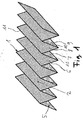
- FIG. 1 shows a perspective view of a heat transfer fabric 1 formed according to the invention.
- the heat transfer fabric 1 is formed of lattice-like arranged aluminum wires 2.
- the heat transfer fabric 1 is accordion-folded, so that there is a zigzag cross-section.
- the heat transfer fabric 1 is subdivided into rectangular surface sections 5, 6, 7, 8, 9.
- the rectangular surface sections 6, 7; 8, 9 each extend in different directions and are interconnected by fold lines 10, 12.
- the rectangular surface sections 7 and 8 are interconnected by a fold line 11.
- the heat transfer fabric 1 is formed in one piece having the shape of a rectangle. By forming the heat transfer fabric 1 gets the zigzag cross section shown in Figure 1.
- the fold lines 10, 12 at the bottom of the heat transfer fabric 1 serve to solder the heat transfer fabric 1 with a voltage applied to the fold lines 10, 12 flow channel boundary surface made of aluminum.
- the fold lines 11 at the top of the heat transfer fabric 1 serve to solder the heat transfer fabric 1 with a voltage applied to the fold lines 11 flow channel boundary surface made of aluminum.
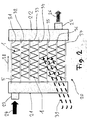
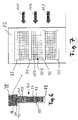
- FIG. 2 schematically shows a heat exchanger 20 according to the invention in accordance with a first exemplary embodiment.
- the heat exchanger 20 comprises two header tanks 21 and 22, which are also referred to as water tanks.
- the collecting box 21 has an inlet connection 23, through which, as indicated by an arrow 24, a medium to be cooled, such as water, enters the collection box 21.
- the collecting box 22 is equipped with an outlet connection 25. Through the outlet nozzle 25 occurs, as indicated by an arrow 26, cooled medium from the collection box 22 from.
- the two header boxes 21 and 22 are connected by a plurality of flat tubes 31 to 37 with each other, one end of each of which opens into the collecting box 21 and the other end respectively into the collecting box 22.
- the flow direction of the medium to be cooled is indicated by the flat tubes 31 to 37.
- a heat transfer fabric 1 as shown in perspective in FIG. 1, is disposed between two flat tubes 31 to 37 in each case.
- the heat transfer fabric 1 is at the fold lines at the top and at the fold lines at the bottom each with a flat tube 31, 32; 33, 34 soldered.
- the heat transfer fabric 1 are arranged so that the zigzag profile extends from the collecting box 21 to the collecting box 22.
- the heat transfer fabric 1, which are arranged in the spaces between the flat tubes 31 to 37, are flowed around perpendicular to the paper plane of cooling air.
- the flow direction of the cooling air is indicated by arrows 39.
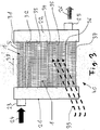
- a heat exchanger 40 is shown, which is constructed similar to the heat exchanger 20 in Figure 2.
- the heat transfer fabric 1 is rotated relative to the figure 2 by 90 degrees, so that the rectangular surface portion 5 between the two Collecting boxes 21 and 22 extends.
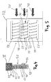
- FIG 4 the view of a section through a heat exchanger 50, which is similar to the heat exchangers 20 and 40 in Figures 2 and 3, shown.
- the cut runs approximately in the middle of the heat exchanger 50 transversely through the flat tubes, so that it practically looks into the flat tubes and onto a collecting box 52.
- the collecting box 52 has an outlet connection 55.
- In the collecting box 52 open flat tubes 58 to 62, which have a rectangular cross-section. Between two flat tubes 58 to 62, 67, 68 a space is recessed in each case.
- air guiding blades 70 made of a heat transfer fabric are arranged so as to give a three-dimensional structure.
- FIG. 5 shows a detail V of FIG. 4 enlarged.
- the air flow direction is indicated by arrows 71 to 73.
- Air guide vanes 75 and 76 are arranged obliquely to the air flow direction 71 to 73.
- the air guide blade 75 is formed from a grid-like wire mesh and has a base 77 having the shape of a rectangle extending longitudinally between two header boxes. From the base 77 two mounting legs 78 and 79 are angled.
- the mounting legs 78 and 79 also each have the shape of a rectangle and are integrally connected to the base 77.
- the mounting leg 78 abuts against the underside of the flat tube 79 and is soldered thereto.
- the mounting leg 79 abuts the top of the flat tube 60 and is soldered thereto.
- FIG. 6 shows a similar section as in FIG. 4 through a heat exchanger 80 according to a further exemplary embodiment.
- a collecting box 82 open flat tubes 88 to 92, 97, 98. Between two flat tubes in each case a gap is provided in which a three-dimensional structure 100 is disposed of a heat transfer fabric.
- FIG. 7 shows a detail VII of FIG. 6 enlarged.
- the air flow is indicated in Figure 7 by arrows 101 to 103.
- the louvers are rotated by 90 degrees relative to the exemplary embodiment illustrated in FIGS. 4 and 5.
- an air-guiding lamella 105 is arranged between the flat tubes 89 and 90 such that the base 107 is arranged in the air flow direction 101 to 103. From the base 107 extend up and down mounting legs into the plane.
- FIG. 8 shows an end section of a flat tube 110 which has a rectangular cross-section.
- the flow direction is indicated, in which the flat tube 110 is flowed through by a medium, for example water.
- a heat transfer fabric 1 Inside the flat tube 110, a heat transfer fabric 1, as shown in perspective in Figure 1, is arranged.
- the zigzag cross-section of the heat transfer fabric 1 extends perpendicular to the flow direction 111 to 114.
- the upper fold lines of the heat transfer fabric 1 are provided with a soldered upper flow channel boundary surface 116 of the flat tube 110.
- the lower fold lines of the heat transfer fabric 1 are soldered to a lower flow channel boundary surface 117 of the flat tube 110.
- a heat transfer fabric 121 is shown in perspective, which is tubular.
- the heat transfer fabric 121 has the shape of a circular cylinder jacket.
- a heat transfer fabric 131 is shown in perspective, which is also tubular, but has an oval cross-section.
- a heat transfer fabric 141 is shown in perspective, which is also tubular, but has a rectangular cross-section.
- FIG. 12 shows a similar sectional view through a heat exchanger 150 as in FIGS. 4 and 6.
- the heat exchanger 150 comprises a collection box 151, open into the flat tubes 152 to 162.
- By an arrow 171 is indicated that between two flat tubes 152, 153; 153, 154; 154, 155 are each two tubular heat transfer fabric 121, as shown in Figure 9, are arranged.
- By an arrow 181 is indicated that between two flat tubes 155, 156; 156, 157; 157,158 are each four heat transfer fabric 131, as shown in Figure 10, are arranged.
- By an arrow 160 is indicated that between two flat tubes 158,159; 159, 160; 160, 161 are each arranged five tubular heat transfer fabrics 141, as shown in Figure 11.
- FIG. 13 shows a section XIII of FIG. 12 enlarged.
- the air flow direction is indicated by arrows 193 to 195.
- the heat transfer fabric 121 may also have an angular, for example, an octagonal, cross section instead of a circular cross section.
- the major axis of the oval cross section of the heat transfer fabric 131 preferably extends perpendicular to the air flow direction 193 to 195.
- the longitudinal axis of the rectangular cross section extends of the heat transfer fabric 141 preferably also perpendicular to the air flow direction 193 to 195.
- the heat transfer fabric is formed of a metal fabric which is soldered between the fluid-carrying tubes, mechanically joined or glued. Through cuts, the individual fibers or wires of the metal fabric can be set up to generate a three-dimensional texture protruding from the plane, through which the heat transfer can be significantly improved.
- the incisions may have all possible geometric shapes, for example rectangular, round and / or elliptical.
- the metal fabric itself may be folded and / or rolled in the form of flat plates. The folding angle can be in the following ranges: 0 to 90 degrees, 2 to 40 degrees, 40 to 90 degrees, 60 to 90 degrees, 40 to 60 degrees and / or 20 to 30 degrees.
- the following angle is possible: 0 to 180 degrees, 1 to 20 degrees, 10 to 50 degrees, 30 to 70 degrees, 60 to 90 degrees, 85 to 120 degrees, 110 to 150 degrees, 135 to 165 degrees and / or 160 to 180 degrees.
- the distance of the stamped forms is at least in the range of the thread thicknesses or wire thicknesses, preferably up to a maximum of 30 mm.
- the wires and filaments used to form the heat transfer fabric each have a thickness that is 10 to 2000 microns.
- the thickness of the wires or filaments is preferably in the following ranges: 40 to 80 ⁇ m, 75 to 190 ⁇ m, 180 to 250 ⁇ m, 240 to 350 ⁇ m, 350 to 1000 ⁇ m, 900 to 1600 ⁇ m and / or 1500 to 2000 ⁇ m.
- the mesh size of the wires or filaments used is 10 to 2000 microns.
- the mesh size is preferably in the following ranges: 40 to 80 ⁇ m, 75 to 190 ⁇ m, 180 to 250 ⁇ m, 240 to 350 ⁇ m, 350 to 1000 ⁇ m, 900 to 1600 ⁇ m and / or 1500 to 2000 ⁇ m.
- Coated fibers, filaments or wires may be used to form the heat transfer fabric. But it is also possible to subsequently coat the heat transfer fabric. The coating can be done before or after the joining process.
- the performance of the heat exchanger can be improved.
- the water flow can be improved.
- the heat exchangers according to the invention have a lower weight than conventional heat exchangers.
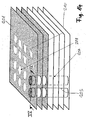
- a heat transfer fabric 201 is disposed across tubes 204, 205.
- passages 208, 210 are recessed for the tubes.
- the shape of the passages 208, 210 is adapted to the cross section of the tubes used. Therefore, the passage 208 has a round or an oval cross-section.
- the passage 210 has a rectangular, in particular square passage.
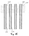
- FIG. 15 shows the view of a section along the line XV-XV in FIG.
- the passages may have a bent edge region 215, which serves to fix the heat transfer fabric 201 to the respective tube.
- the bent edge region may be formed in one piece or in the form of a plurality of tabs.
Landscapes
- Engineering & Computer Science (AREA)
- Physics & Mathematics (AREA)
- Thermal Sciences (AREA)
- Mechanical Engineering (AREA)
- General Engineering & Computer Science (AREA)
- Chemical & Material Sciences (AREA)
- Dispersion Chemistry (AREA)
- Geometry (AREA)
- Heat-Exchange Devices With Radiators And Conduit Assemblies (AREA)
Applications Claiming Priority (1)
| Application Number | Priority Date | Filing Date | Title |
|---|---|---|---|
| DE102005017920A DE102005017920A1 (de) | 2005-04-18 | 2005-04-18 | Wärmetauscher |
Publications (1)
| Publication Number | Publication Date |
|---|---|
| EP1715276A2 true EP1715276A2 (fr) | 2006-10-25 |
Family
ID=36678478
Family Applications (1)
| Application Number | Title | Priority Date | Filing Date |
|---|---|---|---|
| EP20060007872 Withdrawn EP1715276A2 (fr) | 2005-04-18 | 2006-04-13 | Echangeur de chaleur |
Country Status (2)
| Country | Link |
|---|---|
| EP (1) | EP1715276A2 (fr) |
| DE (1) | DE102005017920A1 (fr) |
Cited By (3)
| Publication number | Priority date | Publication date | Assignee | Title |
|---|---|---|---|---|
| EP2418450A3 (fr) * | 2010-08-11 | 2014-03-12 | Fraunhofer-Gesellschaft zur Förderung der angewandten Forschung e.V. | Échangeur de chaleur d'une structure textile tridimensionnelle, son procédé de fabrication et son utilisation |
| US11912106B2 (en) | 2018-12-03 | 2024-02-27 | Eberspächer Catem Gmbh & Co. Kg | Electric heating device |
| US11988463B2 (en) | 2021-03-19 | 2024-05-21 | Brazeway, Inc. | Microchannel heat exchanger for appliance condenser |
Families Citing this family (9)
| Publication number | Priority date | Publication date | Assignee | Title |
|---|---|---|---|---|
| DE102008063700A1 (de) * | 2008-12-19 | 2010-06-24 | Behr Gmbh & Co. Kg | Wärmetauscher |
| DE102012203622A1 (de) | 2012-03-07 | 2013-09-12 | Behr Gmbh & Co. Kg | Gitterstrukturrippe für Wärmeübertrager |
| DE102017217569A1 (de) * | 2017-10-04 | 2019-04-04 | Mahle International Gmbh | Wärmeübertrager, insbesondere für ein Kraftfahrzeug |
| DE102017217565A1 (de) | 2017-10-04 | 2019-04-04 | Mahle International Gmbh | Wärmeübertrager |
| DE102017217568A1 (de) | 2017-10-04 | 2019-04-04 | Mahle International Gmbh | Wärmeübertrager |
| DE102017217567A1 (de) | 2017-10-04 | 2019-04-04 | Mahle International Gmbh | Wärmeübertrager |
| DE102018203299A1 (de) | 2018-03-06 | 2019-09-12 | Mahle International Gmbh | Wärmeübertrager |
| DE102018129160B4 (de) * | 2018-11-20 | 2022-11-24 | Dr. Ing. H.C. F. Porsche Aktiengesellschaft | Verfahren zur Herstellung eines Kühlkörpers |
| DE102019200649A1 (de) | 2019-01-18 | 2020-07-23 | Mahle International Gmbh | Wärmeübertrager |
Family Cites Families (7)
| Publication number | Priority date | Publication date | Assignee | Title |
|---|---|---|---|---|
| DE147857C (fr) * | ||||
| US2044952A (en) * | 1934-08-11 | 1936-06-23 | Frank A Neveu | Radiator core |
| DE69433020T2 (de) * | 1993-10-06 | 2004-06-03 | The Kansai Electric Power Co., Inc. | Plattenwärmetauscher mit Gas-Flüssigkeit Kontakt |
| DE4337634A1 (de) * | 1993-11-04 | 1995-05-11 | Funke Waerme Apparate Kg | Plattenwärmeaustauscher |
| JPH07324884A (ja) * | 1994-05-31 | 1995-12-12 | Showa Alum Corp | 熱交換器用コルゲート・フィン |
| DE29619653U1 (de) * | 1996-11-12 | 1998-03-12 | AEG Hausgeräte GmbH, 90429 Nürnberg | Luftgekühlter Wärmetauscher |
| DE19842622C1 (de) * | 1998-09-17 | 2000-03-09 | Dbb Fuel Cell Engines Gmbh | Turbulenzerzeuger |
-
2005
- 2005-04-18 DE DE102005017920A patent/DE102005017920A1/de not_active Ceased
-
2006
- 2006-04-13 EP EP20060007872 patent/EP1715276A2/fr not_active Withdrawn
Cited By (4)
| Publication number | Priority date | Publication date | Assignee | Title |
|---|---|---|---|---|
| EP2418450A3 (fr) * | 2010-08-11 | 2014-03-12 | Fraunhofer-Gesellschaft zur Förderung der angewandten Forschung e.V. | Échangeur de chaleur d'une structure textile tridimensionnelle, son procédé de fabrication et son utilisation |
| US11912106B2 (en) | 2018-12-03 | 2024-02-27 | Eberspächer Catem Gmbh & Co. Kg | Electric heating device |
| EP3667197B1 (fr) * | 2018-12-03 | 2025-03-26 | Eberspächer catem GmbH & Co. KG | Dispositif de chauffage électrique |
| US11988463B2 (en) | 2021-03-19 | 2024-05-21 | Brazeway, Inc. | Microchannel heat exchanger for appliance condenser |
Also Published As
| Publication number | Publication date |
|---|---|
| DE102005017920A1 (de) | 2006-10-19 |
Similar Documents
| Publication | Publication Date | Title |
|---|---|---|
| DE60219538T2 (de) | Wärmetauscher | |
| DE69509976T2 (de) | Wärmeaustauschrohr | |
| EP1348924B1 (fr) | Echangeur de chaleur à gaz d'échappement pour véhicule | |
| DE202005009948U1 (de) | Wärmeaustauschelement und damit hergestellter Wärmeaustauscher | |
| DE2305056A1 (de) | Rippenrohr-waermeaustauscher | |
| DE2801076B2 (de) | Wärmeaustauscher bestehend aus Schichten von paarweise einander zugeordneten Wänden | |
| DE2330076A1 (de) | Rippenrohr-waermeaustauscher | |
| EP0201665B1 (fr) | Elément de transfert de chaleur comportant des tubes parallèles à ailettes | |
| DE10220532A1 (de) | Wärmetauscher | |
| EP1715276A2 (fr) | Echangeur de chaleur | |
| DE112009000983T5 (de) | Wärmetauscher mit Streckgitterwirbelerzeuger | |
| EP1357345B1 (fr) | Elément d'échange de chaleur ondulé | |
| DE4220823C1 (en) | Two section car heat-exchanger - has lugs bent out from fins common to both sections to form partition between them preventing airflow in that direction | |
| EP1640684A1 (fr) | echangeur de chaleur à tubes plats et ailettes ondulées | |
| EP3491323B1 (fr) | Échangeur de chaleur présentant une structure à micro-canal ou une structure à tube à ailettes | |
| EP1668303B1 (fr) | Réseau d'échange thermique soudé à l'etain | |
| DE10342241A1 (de) | Wärmetauscher | |
| EP0268831B1 (fr) | Lamelle | |
| DE102008020230A1 (de) | Wärmetauscher sowie Wärmetauscherrohr | |
| DE102009041406B3 (de) | Wärmeübertrager | |
| DE102006031676B4 (de) | Turbulenzblech, Verfahren zur Herstellung eines Turbulenzbleches und Verwendung eines Turbulenzbleches | |
| DE19814028A1 (de) | Doppel-Wärmetauscher | |
| EP1832830B1 (fr) | Echangeur de chaleur | |
| EP1398592B1 (fr) | Echangeur de chaleur à tubes plats | |
| WO2004079748A2 (fr) | Distanceur |
Legal Events
| Date | Code | Title | Description |
|---|---|---|---|
| PUAI | Public reference made under article 153(3) epc to a published international application that has entered the european phase |
Free format text: ORIGINAL CODE: 0009012 |
|
| AK | Designated contracting states |
Kind code of ref document: A2 Designated state(s): AT BE BG CH CY CZ DE DK EE ES FI FR GB GR HU IE IS IT LI LT LU LV MC NL PL PT RO SE SI SK TR |
|
| AX | Request for extension of the european patent |
Extension state: AL BA HR MK YU |
|
| STAA | Information on the status of an ep patent application or granted ep patent |
Free format text: STATUS: THE APPLICATION IS DEEMED TO BE WITHDRAWN |
|
| 18D | Application deemed to be withdrawn |
Effective date: 20091103 |