EP1715389A2 - Dispositif et procédé de détection de la position de l'unité montée dans l'appareil de formation d'images - Google Patents
Dispositif et procédé de détection de la position de l'unité montée dans l'appareil de formation d'images Download PDFInfo
- Publication number
- EP1715389A2 EP1715389A2 EP06112626A EP06112626A EP1715389A2 EP 1715389 A2 EP1715389 A2 EP 1715389A2 EP 06112626 A EP06112626 A EP 06112626A EP 06112626 A EP06112626 A EP 06112626A EP 1715389 A2 EP1715389 A2 EP 1715389A2
- Authority
- EP
- European Patent Office
- Prior art keywords
- kth
- mounting slot
- image forming
- nth
- developing unit
- Prior art date
- Legal status (The legal status is an assumption and is not a legal conclusion. Google has not performed a legal analysis and makes no representation as to the accuracy of the status listed.)
- Withdrawn
Links
Images


Classifications
-
- G—PHYSICS
- G03—PHOTOGRAPHY; CINEMATOGRAPHY; ANALOGOUS TECHNIQUES USING WAVES OTHER THAN OPTICAL WAVES; ELECTROGRAPHY; HOLOGRAPHY
- G03G—ELECTROGRAPHY; ELECTROPHOTOGRAPHY; MAGNETOGRAPHY
- G03G15/00—Apparatus for electrographic processes using a charge pattern
- G03G15/01—Apparatus for electrographic processes using a charge pattern for producing multicoloured copies
- G03G15/0105—Details of unit
- G03G15/0121—Details of unit for developing
-
- A—HUMAN NECESSITIES
- A43—FOOTWEAR
- A43C—FASTENINGS OR ATTACHMENTS OF FOOTWEAR; LACES IN GENERAL
- A43C7/00—Holding-devices for laces
- A43C7/02—Flaps; Pockets
-
- A—HUMAN NECESSITIES
- A43—FOOTWEAR
- A43C—FASTENINGS OR ATTACHMENTS OF FOOTWEAR; LACES IN GENERAL
- A43C7/00—Holding-devices for laces
-
- G—PHYSICS
- G03—PHOTOGRAPHY; CINEMATOGRAPHY; ANALOGOUS TECHNIQUES USING WAVES OTHER THAN OPTICAL WAVES; ELECTROGRAPHY; HOLOGRAPHY
- G03G—ELECTROGRAPHY; ELECTROPHOTOGRAPHY; MAGNETOGRAPHY
- G03G2221/00—Processes not provided for by group G03G2215/00, e.g. cleaning or residual charge elimination
- G03G2221/16—Mechanical means for facilitating the maintenance of the apparatus, e.g. modular arrangements and complete machine concepts
- G03G2221/163—Mechanical means for facilitating the maintenance of the apparatus, e.g. modular arrangements and complete machine concepts for the developer unit
Definitions
- the present invention relates to image forming apparatus. More particularly, the present invention relates to a device and method for detecting whether a developing unit is mounted in the right position in an image forming apparatus.
- a color image forming apparatus comprises color developing units respectively storing yellow toner, magenta toner, black toner, and cyan toner and having a non-volatile memory.
- the color image forming apparatus is generally controlled by an inter integrated circuit (I2C) scheme that allows a data signal line and a clock signal line to be shared by many elements.
- I2C inter integrated circuit
- the image forming controller and the developing units share two lines which are a data signal line and a clock signal line.
- An aim of the present invention is to provide a device for detecting the position of a developing unit mounted in an image forming apparatus.
- Another aim of the present invention is to provide a method of detecting the position of identifying a developing unit mounted in an image forming apparatus.
- a device for detecting the position of a developing unit mounted in an image forming apparatus comprises an image forming controller for outputting a clock signal for accessing first to Nth (N is a positive integer greater than 1) developing units, a switching unit for performing a switching operation for connecting the image forming controller to a Kth (K is a positive integer greater than 1 and equal to or smaller than N) mounting slot in order to transmit the clock signal to the Kth mounting slot among first to Nth mounting slots in which the first to Nth developing units are mounted, respectively, first to Nth clock signal lines for connecting the switching unit to the first to Nth mounting slots, and a data line for commonly connecting the image forming controller to the first to Nth mounting slots, wherein the switching unit performs the switching operation in accordance with a switching signal for connecting the image forming controller to the Kth mounting slot and the image forming controller determines whether the Kth developing unit is mounted on the Kth mounting slot in response to an access signal received from the Kth mounting slot.
- a method of detecting the position of a developing unit mounted in an image forming apparatus comprises outputting a switching signal for connecting a Kth (K is a positive integer larger than 1 and smaller than or equal to N) mounting slot among first to Nth mounting slots in which first to Nth (N is a positive integer larger than 1) developing units are mounted, respectively, to an image forming controller, connecting the image forming controller to the Kth mounting slot in accordance with the switching signal, outputting clock signals for accessing the first to Nth developing units from the image forming controller to the Kth mounting slot, outputting data including Kth identification information for identifying the Kth developing unit among identification information on the first to Nth developing units for identifying the first to Nth developing units to the Kth mounting slot, sensing whether an access signal from the Kth mounting slot is received, and recognizing that the Kth developing unit is mounted in the Kth mounting slot in response to the access signal received from the Kth mounting slot.
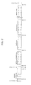
- Figure 1 is a block diagram illustrating a device for detecting the position a developing unit mounted in an image forming apparatus according to an exemplary embodiment of the present invention.
- the device comprises an image forming controller 100, a switching unit 200, a first mounting slot 300, a first developing unit 310, a second mounting slot 320, a second developing unit 330, a third mounting slot 340, a third developing unit 350, a fourth mounting slot 360, a fourth developing unit 370, a first clock signal line 400, a second clock signal line 410, a third clock signal line 420, a fourth clock line signal 430, a data line 500, and a notification unit 600.
- the image forming controller 100 outputs clock signals for accessing the first through fourth developing units 310, 330, 350, and 370 to the switching unit 200.
- the clock signal is a signal for synchronous communication generated by the image forming controller 100 and output to the switching unit 200.
- the image forming controller 100 transmits to the switching unit 200 a switching signal for connection between the image forming controller 10 and a specific mounting slot among the first through the fourth mounting slots 300, 320, 340, and 360.
- a switching signal for connection between the image forming controller 10 and a specific mounting slot among the first through the fourth mounting slots 300, 320, 340, and 360.
- the switching signal is a 2-bit signal to identify the first to the fourth mounting slots 300, 320, 340, and 360.
- the switching signal "00” is output when the image forming controller 100 has to be connected to the first mounting slot 300
- the switching signal "01” is output when the image forming controller 100 has to be connected to the second mounting slot 320
- the switching signal "10” is output when the image forming controller 100 has to be connected to the third mounting slot 340
- the switching signal "11” is output when the image forming controller 100 has to be connected to the fourth mounting slot 360.
- the switching unit 200 In order to transmit a clock signal to any one of the first to the fourth mounting slots 300, 320, 340, and 360 for mounting the first to the fourth developing units 310, 330, 350, and 370, the switching unit 200 performs a switching operation for connecting the image forming controller 100 to one of the mounting slots 300 through 360 according to the switching signal received from the image forming controller 100.
- the switching unit 200 performs a switching operation so that the first clock signal line 400 which is connected to the first mounting slot 300 is connected to the image forming controller 100. Therefore, by a switching operation of the switching unit 200, the clock signal of the image forming controller 100 can be transmitted to the first mounting slot 300 through the first clock signal line 400.
- the switching unit 200 performs a switching operation so that the second clock signal line 410 which is connected to the second mounting slot 320 is connected to the image forming controller 100. Therefore, by a switching operation of the switching unit 200, the clock signal of the image forming controller 100 can be transmitted to the second mounting slot 320 through the second clock signal line 410.
- the switching unit 200 performs a switching operation so that the third clock signal line 420 which is connected to the third mounting slot 340 is connected to the image forming controller 100. Therefore, by a switching operation of the switching unit 200, the clock signal of the image forming controller 100 can be transmitted to the first mounting slot 340 through the first clock signal line 420.
- the switching unit 200 performs a switching operation so that the fourth clock signal 430 which is connected to the fourth mounting slot 360 is connected to the image forming controller 100. Therefore, by a switching operation of the switching unit 200, the clock signal of the image forming controller 100 can be transmitted to the fourth mounting slot 360 through the fourth clock signal line 430.
- the first through the fourth clock signal lines 400, 410, 420, and 430 respectively connect the switching unit 200 to the first through fourth mounting slots 300, 320, 340, and 360.
- the first through fourth clock signal lines 400, 410, 420, and 430 act as channels through which the clock signals are respectively transmitted to the first through the fourth mounting slots 300, 320, 340, and 360.
- the data line 500 connects the image forming controller 100 to the first through the fourth mounting slots 300, 320, 340, and 360. Therefore, data are exchanged between the image forming controller 100 and the first through the fourth mounting slots 300, 320, 340, and 360 through the data line 500.
- the image forming controller 100 When the image forming controller 100 receives an access signal from any one of the first to the fourth mounting slots 300, 320, 340, and 360, it recognizes that any one developing unit of the first to the fourth developing units 310, 330, 350, and 370 is respectively mounted in any one mounting slot of the first to the fourth mounting slots 300, 320, 340, and 360.
- the image forming controller 100 outputs through the data line 500 data including any one of identification information among identification information on the first through the fourth developing unit to the mounting slot which has received the clock signal.
- the image forming controller 100 adds the address information on the developing unit as identification information on the developing unit to data.
- Figure 2 is a diagram illustrating data to which identification information of a developing unit is added according to an exemplary embodiment of the present invention. As shown in Figure 2, it is confirmed that a device address as the identification information of the developing unit is added to the data.
- the second developing unit 330 should be mounted in the second mounting slot 320.
- the image forming controller 100 outputs data to which the identification information of the second developing unit 330 corresponding to the identification information of the second developing unit 330 is added to the second mounting slot 320. If an access signal from the second mounting slot 320 is received, the image forming controller 100 recognizes that the second developing unit 330 is mounted in the second mounting slot 320.
- the image forming controller 100 adds any one identification information among other identification information (identification information of the first developing unit, the third developing unit, and the fourth developing unit) except the identification information of the second developing unit to data and outputs the data to the second mounting slot 320.
- the image forming controller 100 recognizes that the first developing unit 310 is wrongly mounted in the second mounting slot 320. Because the first developing unit 310 that should be mounted in the first mounting slot 300 is mounted in the second mounting slot 320, the mounting is wrong.
- the image forming controller 100 When the data to which the identification information of the first developing unit is added are output to the second mounting slot 320, if the access signal from the second mounting slot 320 is not received, the image forming controller 100 outputs data to which the identification information of the third developing unit and the fourth developing unit is added in the order to the second mounting slot 320. If the access signal from the second mounting slot 320 is not received, the image forming controller 100 detects that no developing unit is mounted in the second mounting slot 320.
- the notification unit 600 notifies a user of the detection result of the image forming controller 100. For example, if a mounting slot receiving the clock signal is the second mounting slot 320, according to the detection result that the second developing unit 330 is mounted in the second mounting slot 320, the notification unit 600 notifies a user that the second developing unit 330 is rightly mounted in the second mounting slot 320. Further, according to the detection result that any one among the first developing unit 310, the third developing unit 350 or the fourth developing unit 370 is mounted in the second mounting slot 320, the notification unit 600 notifies a user that other developing unit except the second developing unit 330 is wrongly mounted in the second mounting slot 320. Further, according to the detection result that no developing unit is mounted in the second mounting slot 320, the notification unit 600 notifies a user that no developing unit is mounted in the second mounting slot 320.
- a device for detecting the position a developing unit mounted in an image forming apparatus comprises the first to the fourth developing units 310, 330, 350, and 370, but the clock signal lines are added or subtracted depending on addition or subtraction of the developing units.
- Figure 3 is a flow chart illustrating a method of detecting the position of a developing unit mounted in an image forming apparatus according to an exemplary embodiment of the present invention.
- a switching signal for connecting a Kth (K is a positive integer larger than 1 and smaller than N) mounting slot among first to Nth mounting slots in which respective first to Nth (N is a positive integer larger than 1) developing units are mounted to an image forming controller is output at step 700.
- An example of the switching signal is illustrated in Table 1. As illustrated in Table 1, the number of bits of the switching signal is dependent on the number of the developing units.
- step 700 the image forming controller is connected to the Kth mounting slot at step 702.
- a clock signal for accessing the first to Nth developing units is output from the image forming controller to Kth mounting slot at step 704.
- step 704 data including Kth identification information for identifying the Kth developing unit among the identification information of the first to Nth developing units for identifying the first to Nth developing units are output to the Kth mounting slot at step 706.
- the address information of the Kth developing unit to which data is added is output to the Kth mounting slot as the Kth identification information.
- step 706 it is sensed whether an access signal from the Kth mounting slot is received at step 708.
- step 708 if the access signal from the Kth mounting slot is received, it is determined that the Kth developing unit is mounted in the Kth mounting slot at step 710.
- a notification unit notifies a user that the Kth developing unit is mounted in the Kth mounting slot at step 712.
- step 706 if the access signal from Kth mounting slot is not received, data to which other identification information except the Kth identification information is added are output to the Kth mounting slot at step 714.
- step 714 it is sensed whether the access signal from the Kth mounting slot is received at step 716.
- step 716 if the access signal from the Kth mounting slot is received, it is determined that the developing unit corresponding to other identification information is mounted in the Kth mounting slot at step 718.
- the notification unit notifies a user that the developing unit corresponding to other identification information is mounted in the Kth mounting slot at step 720.
- the notification unit notifies a user that no developing unit is mounted in the Kth mounting slot at step 722.
- the exemplary embodiments of the present invention can be written as computer readable codes/instructions/programs and can be implemented in general-use digital computers that execute the programs using a computer readable recording medium.
- the computer readable recording medium comprise magnetic storage media, such as ROM, floppy disks, hard disks, magnetic tapes, and the like, optical recording media, such as CD-ROMs, DVDs and the like, and storage media such as carrier waves, such as transmission through the Internet.
- the computer readable recording medium can also be distributed over network coupled computer systems so that the computer readable code is stored and executed in a distributed fashion.
- functional programs, codes, and code segments for accomplishing the present invention can be easily construed by programmers skilled in the art to which the present invention pertains.
- the device and method of the present invention sense that color developing units of an image forming apparatus are not mounted in a designated position and notify a user of this fact.
- the device and method of the present invention prevent unwanted sheets from being printed because the color developing units are not mounted in the right position.
Landscapes
- Physics & Mathematics (AREA)
- General Physics & Mathematics (AREA)
- Control Or Security For Electrophotography (AREA)
- Color Electrophotography (AREA)
- Length Measuring Devices By Optical Means (AREA)
- Dry Development In Electrophotography (AREA)
Priority Applications (1)
| Application Number | Priority Date | Filing Date | Title |
|---|---|---|---|
| EP12172820.8A EP2503398B1 (fr) | 2005-04-18 | 2006-04-13 | Dispositif et procédé de détection de la position de l'unité montée dans l'appareil de formation d'images |
Applications Claiming Priority (1)
| Application Number | Priority Date | Filing Date | Title |
|---|---|---|---|
| KR1020050031929A KR100644692B1 (ko) | 2005-04-18 | 2005-04-18 | 장착된 현상기의 식별장치 및 방법 |
Related Child Applications (1)
| Application Number | Title | Priority Date | Filing Date |
|---|---|---|---|
| EP12172820.8A Division EP2503398B1 (fr) | 2005-04-18 | 2006-04-13 | Dispositif et procédé de détection de la position de l'unité montée dans l'appareil de formation d'images |
Publications (2)
| Publication Number | Publication Date |
|---|---|
| EP1715389A2 true EP1715389A2 (fr) | 2006-10-25 |
| EP1715389A3 EP1715389A3 (fr) | 2010-04-21 |
Family
ID=36569134
Family Applications (2)
| Application Number | Title | Priority Date | Filing Date |
|---|---|---|---|
| EP06112626A Withdrawn EP1715389A3 (fr) | 2005-04-18 | 2006-04-13 | Dispositif et procédé de détection de la position de l'unité montée dans l'appareil de formation d'images |
| EP12172820.8A Ceased EP2503398B1 (fr) | 2005-04-18 | 2006-04-13 | Dispositif et procédé de détection de la position de l'unité montée dans l'appareil de formation d'images |
Family Applications After (1)
| Application Number | Title | Priority Date | Filing Date |
|---|---|---|---|
| EP12172820.8A Ceased EP2503398B1 (fr) | 2005-04-18 | 2006-04-13 | Dispositif et procédé de détection de la position de l'unité montée dans l'appareil de formation d'images |
Country Status (4)
| Country | Link |
|---|---|
| US (3) | US7937001B2 (fr) |
| EP (2) | EP1715389A3 (fr) |
| KR (1) | KR100644692B1 (fr) |
| CN (1) | CN100511011C (fr) |
Families Citing this family (3)
| Publication number | Priority date | Publication date | Assignee | Title |
|---|---|---|---|---|
| JP2006030963A (ja) * | 2004-06-15 | 2006-02-02 | Canon Inc | ユニットおよび電子写真画像形成装置 |
| KR101080183B1 (ko) * | 2008-04-04 | 2011-11-07 | (주)멜파스 | 가장자리 위치 인식 특성이 개선된 접촉 감지 장치 |
| JP2013145336A (ja) * | 2012-01-16 | 2013-07-25 | Ricoh Co Ltd | 画像形成装置、画像形成方法及び画像形成プログラム |
Citations (1)
| Publication number | Priority date | Publication date | Assignee | Title |
|---|---|---|---|---|
| EP0927916A2 (fr) * | 1997-12-29 | 1999-07-07 | Canon Kabushiki Kaisha | Unité de traitement montée de manière à pouvoir être retirée d'un appareil de formation d'images |
Family Cites Families (14)
| Publication number | Priority date | Publication date | Assignee | Title |
|---|---|---|---|---|
| US4961088A (en) | 1989-04-20 | 1990-10-02 | Xerox Corporation | Monitor/warranty system for electrostatographic reproducing machines using replaceable cartridges |
| US5220379A (en) * | 1990-07-26 | 1993-06-15 | Konica Corporation | Color image forming apparatus |
| JP4365951B2 (ja) * | 1999-09-09 | 2009-11-18 | キヤノン株式会社 | 画像形成装置 |
| JP2001209280A (ja) * | 2000-01-26 | 2001-08-03 | Canon Inc | 画像形成装置およびその装置ユニット |
| JP2001296786A (ja) | 2000-04-14 | 2001-10-26 | Canon Inc | プロセスカートリッジおよび画像形成装置 |
| JP4081963B2 (ja) * | 2000-06-30 | 2008-04-30 | セイコーエプソン株式会社 | 記憶装置および記憶装置に対するアクセス方法 |
| US6549732B2 (en) | 2000-07-24 | 2003-04-15 | Minolta Co., Ltd. | Processing cartridge for image forming apparatus having a non-volatile memory |
| JP2002040904A (ja) | 2000-07-24 | 2002-02-08 | Minolta Co Ltd | プロセスカートリッジ |
| JP4379662B2 (ja) | 2000-11-30 | 2009-12-09 | 株式会社リコー | 画像形成装置、画像形成装置に用いるカートリッジの使用管理方法 |
| JP3596871B2 (ja) | 2001-09-28 | 2004-12-02 | キヤノン株式会社 | 液体収納容器 |
| US6915094B2 (en) * | 2002-01-16 | 2005-07-05 | Canon Kabushiki Kaisha | Composition for accessing a memory in image formation apparatus and method for accessing a memory in image formation apparatus |
| JP4210983B2 (ja) | 2002-10-16 | 2009-01-21 | セイコーエプソン株式会社 | 液体噴射装置 |
| JP2004174915A (ja) * | 2002-11-27 | 2004-06-24 | Canon Inc | 画像形成装置 |
| KR100553897B1 (ko) * | 2003-10-31 | 2006-02-24 | 삼성전자주식회사 | 메모리를 이용한 화상형성장치의 소모품 관리 장치 |
-
2005
- 2005-04-18 KR KR1020050031929A patent/KR100644692B1/ko not_active Expired - Fee Related
-
2006
- 2006-02-24 US US11/360,465 patent/US7937001B2/en not_active Expired - Fee Related
- 2006-04-13 EP EP06112626A patent/EP1715389A3/fr not_active Withdrawn
- 2006-04-13 EP EP12172820.8A patent/EP2503398B1/fr not_active Ceased
- 2006-04-18 CN CNB2006100752795A patent/CN100511011C/zh not_active Expired - Fee Related
-
2009
- 2009-10-20 US US12/588,576 patent/US8068747B2/en not_active Expired - Fee Related
-
2011
- 2011-09-16 US US13/137,841 patent/US20120243883A1/en not_active Abandoned
Patent Citations (1)
| Publication number | Priority date | Publication date | Assignee | Title |
|---|---|---|---|---|
| EP0927916A2 (fr) * | 1997-12-29 | 1999-07-07 | Canon Kabushiki Kaisha | Unité de traitement montée de manière à pouvoir être retirée d'un appareil de formation d'images |
Also Published As
| Publication number | Publication date |
|---|---|
| KR20060109681A (ko) | 2006-10-23 |
| US7937001B2 (en) | 2011-05-03 |
| US20060233557A1 (en) | 2006-10-19 |
| EP2503398A2 (fr) | 2012-09-26 |
| EP2503398A3 (fr) | 2013-02-20 |
| CN100511011C (zh) | 2009-07-08 |
| EP1715389A3 (fr) | 2010-04-21 |
| US20120243883A1 (en) | 2012-09-27 |
| US8068747B2 (en) | 2011-11-29 |
| EP2503398B1 (fr) | 2020-09-23 |
| US20100040384A1 (en) | 2010-02-18 |
| CN1854930A (zh) | 2006-11-01 |
| KR100644692B1 (ko) | 2006-11-10 |
Similar Documents
| Publication | Publication Date | Title |
|---|---|---|
| US7711879B2 (en) | Data transfer method and data transfer device | |
| US6823400B2 (en) | Method and apparatus for serial communications between a host apparatus and optional equipment having unique identification values | |
| US6817794B2 (en) | Printer | |
| US20080181651A1 (en) | Image forming apparatus provided with function to calculate charge based on the number of sheets printed, print system including image forming apparatus, method for counting the number of sheets printed executed by image forming apparatus, and program for counting the number of sheets printed executed by image forming apparatus | |
| JP5238369B2 (ja) | データ受信装置、データ受信方法及びデータ受信プログラム | |
| US8068747B2 (en) | Device and method for detecting position of unit mounted in image forming apparatus | |
| JP5434173B2 (ja) | 画像形成装置、及び画像形成方法 | |
| US7027765B2 (en) | Apparatus and method for identifying paper cassettes | |
| CN101207637A (zh) | 自动设置网络打印装置端口的方法及其网络打印装置 | |
| US7168015B2 (en) | TF-determination apparatus, and TF-determination method as well as program to be executed for implementing the TF-determination method | |
| US7653717B2 (en) | Equipment management apparatus, equipment management system, and equipment management method | |
| JP2005202643A (ja) | シリアルデータ通信装置および画像形成装置 | |
| JP5669419B2 (ja) | 画像形成装置 | |
| US4493084A (en) | Belt synchronous check system for a line printer | |
| JP3401729B2 (ja) | スプリットバス制御回路 | |
| RU2855973C1 (ru) | Устройство управления расходным компонентом, способ аутентификации расходного компонента и расходный компонент для устройства формирования изображений (варианты) | |
| US20070121563A1 (en) | Method and apparatus to determine wireless network link | |
| US20030021390A1 (en) | Device for connection of a device on a telephone line | |
| JP4466523B2 (ja) | 故障診断システム、画像形成装置および故障診断方法 | |
| JP2005236649A (ja) | 通信制御プログラム | |
| JP2006099169A (ja) | 電気機器 | |
| JP2000165565A (ja) | 画像形成装置 | |
| JP2007265108A (ja) | バスブリッジ | |
| JPS63268329A (ja) | ネツトワ−クシステム | |
| JPH07143150A (ja) | ループ型伝送装置 |
Legal Events
| Date | Code | Title | Description |
|---|---|---|---|
| PUAI | Public reference made under article 153(3) epc to a published international application that has entered the european phase |
Free format text: ORIGINAL CODE: 0009012 |
|
| 17P | Request for examination filed |
Effective date: 20060413 |
|
| AK | Designated contracting states |
Kind code of ref document: A2 Designated state(s): AT BE BG CH CY CZ DE DK EE ES FI FR GB GR HU IE IS IT LI LT LU LV MC NL PL PT RO SE SI SK TR |
|
| AX | Request for extension of the european patent |
Extension state: AL BA HR MK YU |
|
| PUAL | Search report despatched |
Free format text: ORIGINAL CODE: 0009013 |
|
| AK | Designated contracting states |
Kind code of ref document: A3 Designated state(s): AT BE BG CH CY CZ DE DK EE ES FI FR GB GR HU IE IS IT LI LT LU LV MC NL PL PT RO SE SI SK TR |
|
| AX | Request for extension of the european patent |
Extension state: AL BA HR MK YU |
|
| 17Q | First examination report despatched |
Effective date: 20100621 |
|
| AKX | Designation fees paid |
Designated state(s): DE FR GB NL |
|
| RAP1 | Party data changed (applicant data changed or rights of an application transferred) |
Owner name: SAMSUNG ELECTRONICS CO., LTD. |
|
| STAA | Information on the status of an ep patent application or granted ep patent |
Free format text: STATUS: THE APPLICATION IS DEEMED TO BE WITHDRAWN |
|
| 18D | Application deemed to be withdrawn |
Effective date: 20150303 |