EP1715455A1 - Verfahren und System zur Transformation von 2D Bildbereichsdaten in eine dichte 3D Entfernungskarte - Google Patents
Verfahren und System zur Transformation von 2D Bildbereichsdaten in eine dichte 3D Entfernungskarte Download PDFInfo
- Publication number
- EP1715455A1 EP1715455A1 EP06111806A EP06111806A EP1715455A1 EP 1715455 A1 EP1715455 A1 EP 1715455A1 EP 06111806 A EP06111806 A EP 06111806A EP 06111806 A EP06111806 A EP 06111806A EP 1715455 A1 EP1715455 A1 EP 1715455A1
- Authority
- EP
- European Patent Office
- Prior art keywords
- image
- interest
- image frame
- image sensor
- region
- Prior art date
- Legal status (The legal status is an assumption and is not a legal conclusion. Google has not performed a legal analysis and makes no representation as to the accuracy of the status listed.)
- Withdrawn
Links
Images



Classifications
-
- G—PHYSICS
- G06—COMPUTING OR CALCULATING; COUNTING
- G06T—IMAGE DATA PROCESSING OR GENERATION, IN GENERAL
- G06T7/00—Image analysis
- G06T7/50—Depth or shape recovery
-
- G—PHYSICS
- G06—COMPUTING OR CALCULATING; COUNTING
- G06V—IMAGE OR VIDEO RECOGNITION OR UNDERSTANDING
- G06V10/00—Arrangements for image or video recognition or understanding
- G06V10/20—Image preprocessing
- G06V10/22—Image preprocessing by selection of a specific region containing or referencing a pattern; Locating or processing of specific regions to guide the detection or recognition
- G06V10/235—Image preprocessing by selection of a specific region containing or referencing a pattern; Locating or processing of specific regions to guide the detection or recognition based on user input or interaction
-
- G—PHYSICS
- G06—COMPUTING OR CALCULATING; COUNTING
- G06V—IMAGE OR VIDEO RECOGNITION OR UNDERSTANDING
- G06V10/00—Arrangements for image or video recognition or understanding
- G06V10/20—Image preprocessing
- G06V10/24—Aligning, centring, orientation detection or correction of the image
-
- G—PHYSICS
- G06—COMPUTING OR CALCULATING; COUNTING
- G06V—IMAGE OR VIDEO RECOGNITION OR UNDERSTANDING
- G06V20/00—Scenes; Scene-specific elements
-
- G—PHYSICS
- G06—COMPUTING OR CALCULATING; COUNTING
- G06V—IMAGE OR VIDEO RECOGNITION OR UNDERSTANDING
- G06V2201/00—Indexing scheme relating to image or video recognition or understanding
- G06V2201/12—Acquisition of 3D measurements of objects
Definitions
- the present invention relates generally to the field of video image processing and context based scene understanding and behavior analysis. More specifically, the present invention pertains to systems and methods for transforming two-dimensional image domain data into a 3D dense range map.
- Video surveillance systems are used in a variety of applications to detect and monitor objects within an environment.
- security applications for example, such systems are sometimes employed to detect and track individuals or vehicles entering or leaving a building facility or security gate, or to monitor individuals within a store, office building, hospital, or other such setting where the health and/or safety of the occupants may be of concern.
- security applications for example, such systems have been used to detect the presence of individuals at key locations within an airport such as at a security gate or parking garage.
- Automation of digital image processing sufficient to perform scene understanding (SU) and/or behavioral analysis of video images is typically accomplished by comparing images acquired from one or more video cameras and then comparing those images with a previously stored reference model that represents a particular region of interest.
- scene images from multiple video cameras are obtained and then compared against a previously stored CAD site model or map containing the pixel coordinates for the region of interest.
- events such as motion detection, motion tracking, and/or object classification/scene understanding can be performed on any new objects that may have moved in any particular region and/or across multiple regions using background subtraction or other known techniques.
- a stereo triangulation technique employing multiple image sensors can be used to compute the location of an object within the region of interest.
- the present invention pertains to systems and methods for transforming two-dimensional image domain data into a 3D dense range map.
- An illustrative method in accordance with an exemplary embodiment of the present invention may include the steps of acquiring at least one image frame from an image sensor, selecting via manual and/or algorithm-assisted segmentation the key physical background regions of the image, determining the geo-location of three or more reference points within each selected region of interest, and transforming 2D image domain data from each selected region of interest into a 3D dense range map containing physical features of one or more objects within the image frame.
- a manual segmentation process can be performed to define a number of polygonal zones within the image frame, each polygonal zone representing a corresponding region of interest.
- the polygonal zones may be defined, for example, by selecting a number of reference points on the image frame using a graphical user interface.
- a software tool can be utilized to assist the user to hand-segment and label (e.g. "road”, “parking lot”, “building”, etc.) the selected physical regions of the image frame.
- the graphical user interface can be configured to prompt the user to establish a 3D coordinate system to determine the geo-location of pixels within the image frame.
- the graphical user interface may prompt the user to enter values representing the distances between the image sensor to a first and second reference point used in defining a polygonal zone, and then measure the distance between those reference points.
- the graphical user interface can be configured to prompt the user to enter values representing the distance to first and second reference points of a planar triangle defined by the polygonal zone, and then measure the included angle between the lines forming the two distances.
- an algorithm or routine can be configured to calculate the 3D coordinates for the reference points originally represented by coordinate pair in 2D.
- the 2D image domain data inputted within the polygonal zone is transformed into a 3D dense range map using an interpolation technique, which converts 2D image domain data ( i . e . pixels) into a 3D look-up table so that each pixel within the image frame corresponds to real-world coordinates defined by a 3D coordinate system.
- the same procedure can be applied to another polygonal zone defined by the user, if desired.
- the physical features of one or more objects located within a region of interest may then be calculated and outputted to a user and/or other algorithms.
- the physical features may be expressed as a physical feature vector containing those features associated with each object as well as features relating to other objects and/or static background within the image frame.
- the algorithm or routine can be configured to dynamically update the 3D look-up table with new or modified information for each successive image frame acquired and/or for each new region of interest defined by the user.
- An illustrative video surveillance system in accordance with an exemplary embodiment of the present invention may include an image sensor adapted to acquire images containing at least one region of interest, display means for displaying images from the image sensor within an image frame, and processing means for determining the geo-location of one or more objects within the image frame.
- the processing means may comprise a microprocessor/CPU or other suitable processor adapted to run an algorithm or routine that transforms two-dimensional image data received from the image sensor into a 3D dense range map containing physical features of one or more objects located within the image frame.
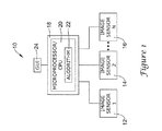
- Figure 1 is a diagrammatic view showing an illustrative video surveillance system in accordance with an exemplary embodiment of the present invention
- Figure 2 is a flow chart showing an illustrative algorithm or routine for transforming two-dimensional image domain data into a 3D dense range map
- Figure 3 is a diagrammatic view showing an illustrative step of establishing a 3D camera coordinate system
- Figure 4 is a diagrammatic view showing an illustrative step of determining the geo-location of an object within a polygonal zone
- Figure 5 is a diagrammatic view showing an illustrative step of transforming two-dimensional image domain data into a 3D look-up table
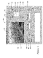
- Figure 6 is a pictorial view showing an illustrative graphical user interface for use in transforming two-dimensional image domain data into a 3D dense range map;
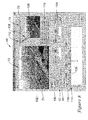
- Figure 7 is a pictorial view showing an illustrative step of defining a number of reference points of a polygonal zone using the graphical user interface of Figure 6;
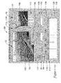
- Figure 8 is a pictorial view showing the graphical user interface of Figure 6 once a polygonal zone has been selected within the image frame;
- Figure 9 is a pictorial view showing an illustrative step of inputting values for those reference points selected using the graphical user interface of Figure 6;
- Figure 10 is a pictorial view showing the graphical user interface of Figure 6 prompting the user to save a file containing the 3D look-up table data.
- FIG. 1 is a diagrammatic view showing an illustrative video surveillance system 10 in accordance with an exemplary embodiment of the present invention.
- the surveillance system 10 may include a number of image sensors 12,14,16 each of which can be networked together via a computer 18 to detect the occurrence of a particular event within the environment.
- each of the image sensors 12,14,16 can be positioned at various locations of a building or structure and tasked to acquire video images that can be used to monitor individuals and/or other objects located within a room, hallway, elevator, parking garage, or other such space.
- the type of image sensor 12,14,16 employed e.g.
- video may vary depending on the installation location and/or the type of objects to be tracked.
- video is used herein with respect to specific devices and/or examples, such term should be interpreted broadly to include any images generated by an image sensor. Examples of other image spectrums contemplated may include, but are not limited to, near infrared (NIR), Midwave Infrared (MIR), Longwave Infrared (LIR), and/or passive or active Milli-Meter Wave (MMW).
- NIR near infrared
- MIR Midwave Infrared
- LIR Longwave Infrared
- MMW passive or active Milli-Meter Wave
- the computer 18 can include software and/or hardware adapted to process real-time images received from one or more of the image sensors 12,14,16 to detect the occurrence of a particular event.
- the microprocessor/CPU 20 can be configured to run an algorithm or routine 22 that acquires images from one of the image sensors 12,14,16, and then transforms such images into a 3D dense range map containing various background and object parameters relating to a region of interest (ROI) selected by a user via a graphical user-interface (GUI) 24.
- the 3D dense range map may comprise, for example, a 3D look-up table containing the coordinates of a particular scene ( i . e .
- the computer 18 can then run various low-level and/or high-level processing algorithms or routines for detecting the occurrence of events within the scene using behavior classification, object classification, intent analysis, or other such technique.
- the computer 18 can be configured to run a behavioral analysis engine similar to that described with respect to U.S. Application Serial No. 10/938,244 , entitled "Unsupervised Learning Of Events In A Video Sequence", which is incorporated herein by reference in its entirety.
- the computer 18 can include an event library or database of programmed events, which can be dynamically updated by the user to task the video surveillance system 10 in a particular manner.
- Figure 2 is a flow chart showing an illustrative algorithm or routine for transforming two-dimensional image domain data into a 3D dense range map using the illustrative video surveillance system 10 of Figure 1.
- the algorithm or routine depicted generally by reference number 26 in Figure 2, may begin at block 28 with the acquisition of one or more image frames within a field of view using one or more of the image sensors 12,14,16 in Figure 1.
- block 28 may represent the acquisition of real-time images from a single digital video camera installed at a security gate, building entranceway, parking lot, or other location where it is desired to track individuals, automobiles, or other objects moving within the entire or part of the FOV of the image sensor.
- the user may next input various parameters relating to at least one region of interest to be monitored by the surveillance system 10, as indicated generally by block 30.
- the selection of one or more regions of interest, where the 3D range information is desired can be accomplished using a manual segmentation process on the image frame, wherein the computer 18 prompts the user to manually select a number of points using the graphical user interface 24 to define a closed polygon structure that outlines the particular region of interest.
- the computer 18 may prompt the user to select at least three separate reference points on the graphical user interface 24 to define a particular region of interest such as a road, parking lot, building, security gate, tree line, sky, or other desired geo-location.
- the context information for each region of interest selected can then be represented on the graphical user interface 24 as a closed polygonal line, a closed curved line, or a combination of the two.
- the polygonal lines and/or curves may be used to demarcate the outer boundaries of a planar or non-planar region of interest, forming a polygonal zone wherein all of the pixels within the zone represent a single context class (e.g. "road”, "building”, “parking lot”, etc.).
- at least three reference points are required to define a polygonal zone, although a greater number of points may be used for selecting more complex regions on the graphical user interface 24, if desired.
- the algorithm or routine 26 may next prompt the user to setup a 3D camera coordinate system that can be utilized to determine the distance of the image sensor from each reference point selected on the graphical user interface 24, as indicated generally by block 32.
- An illustrative step 32 showing the establishment of a 3D camera coordinate system may be understood by reference to Figure 3, which shows a 3D camera coordinate system 34 for a planar polygonal zone 36 defined by four reference points R 1 , R 2 , R 3 , and R 4 .
- a reference point or origin 38 of (X,Y,Z) (0,0,0) can be assigned to the image sensor 40, with each axis (X,Y,Z) corresponding to various camera axes.
- the user may first measure the distance from one of the reference points to the image sensor 40 using a laser range finder or other suitable instrument, measure the distance from that reference point to another reference point, and then measure the distance from that reference point back to the image sensor 40. The process may then be repeated for every pair of reference points.
- such process may include the steps of measuring the distance D 2 between the image sensor 40 and reference point R 2 , measuring distance D 2 ⁇ 4 between reference point R 2 and another reference point such as R 4 , and then measuring the distance D 4 between that reference point R 4 back to the origin 38 of the image sensor 40.
- a triangle 42 can then be displayed on the graphical user interface 24 along with the pixel coordinates of each reference point R 2 , R 4 forming that triangle 42.
- a similar process can then be performed to determine the pixel coordinates of the other reference points R 1 and R 3 , R 1 and R 2 , R 4 and R 3 , producing three additional triangles that, in conjunction with triangle 42, form a polyhedron having a vertex located at the origin 38 and a base representing the planar polygonal zone 36.
- the distance to two points and their included angle from the camera can be measured.
- the angle can be determined using a protractor or other suitable instrument for measuring the angle ⁇ between the two reference points R 2 and R 4 from the camera instead of determining the distance D 2 ⁇ 4 between those two points.
- a laser range finder or other suitable instrument can be utilized to measure the distances D 2 and D 4 between each of the reference points R 2 and R 4 and the origin 38.
- a similar process can then be performed to determine the pixel coordinates of the other reference points R 1 and R 3 , R 1 and R 2 , and R 4 and R 3 .
- a protractor or other suitable instrument located at R 4 can then be used to measure the angle ⁇ between the reference point R 2 and the origin 38 at R 4 .
- a laser range finder or other suitable instrument can then be utilized to measure the distances D 2 ⁇ 4 and D 4 .
- the algorithm or routine 26 may next determine the geo-location of one or more objects within the polygonal zone 36, as indicated generally by block 44 in Figure 2.
- An illustrative step 44 of determining the geo-location of an object within a polygonal zone may be understood by reference to Figure 4, which shows an individual 46 moving from time "t" to time "t+1" within the polygonal zone 36 of Figure 3.
- movement of the individual 46 may be tracked by corresponding the pixel coordinates of the polygonal zone 36 with that of the detected individual 46, using the image sensor 40 as the vertex.
- a contact point 48 such as the individual's feet may be utilized as a reference point to facilitate transformation of pixel features to physical features during later analysis stages. It should be understood, however, that other contact points may be selected, depending on object(s) to be detected as well as other factors. If, for example, the object to be monitored is an automobile, then a contact point such as a tire or wheel may be utilized, if desired.
- the algorithm or routine 26 next transforms the 2D image domain data represented in pixels into a 3D dense range map of the geo-location, as indicated generally by block 50 in Figure 2.
- An interpolation technique may be employed to convert the 2D image domain data into a 3D look-up table so that each pixel within the image frame corresponds to the defined 3D camera coordinate system.
- the 3D look-up table may include X, Y, and Z parameters representing the coordinates of the geo-location, a region name parameter identifying the name of the ROI containing the coordinates, and a region type parameter describing the type of ROI (e.g. road, parking lot, building, etc.) defined.
- Other information such as lighting conditions, time/date, image sensor type, etc. may also be provided as parameters in the 3D look-up table, if desired.
- An illustrative step 50 of transforming 2D image domain data into a 3D look-up table 52 may be understood by reference to Figure 5.
- each image pixel 54 within a 2D image frame 56 can be mapped into the 3D look-up table 52 by correlating the pixel's 54 coordinates (u,v) with the 3D camera coordinates established at step 32 of Figure 2.
- each pixel coordinate (u,v) is matched with the corresponding 3D camera coordinate, as indicated generally by arrow 58, it may be assigned a separate parameter block 60 of (X,Y,Z) within the 3D look-up table 52, with the "X", "Y", and "Z" parameters of each parameter block 60 representing the coordinates of the geo-location for that pixel.
- each of the parameter blocks 60 may also include a "t" parameter representing the type of ROI within the scene. If, for example, the coordinates of the parameter block 60 correspond to an ROI such as a parking lot, then the "t" parameter of that block 60 may contain text or code (e.g. "parking lot", "code 1", etc.) signifying that the ROI is a parking lot.
- other ROI parameters such as size, global location ( e . g . GPS coordinates), distance and location relative to other ROI's, etc. may also be provided as parameters within the 3D look-up table 52.
- the 3D look-up table 52 may include parameter blocks 60 from multiple ROI's located within an image frame 56.
- the 3D look-up table 52 may include a first number of parameter blocks 60a representing a first ROI in the image frame 56 (e.g. a parking lot), and a second number of parameter blocks 60b representing a second ROI in the image frame 56 ( e . g . a building entranceway).
- the 3D look-up table 52 can include parameter blocks 60 for multiple image frames 56 acquired either from a single image sensor, or from multiple image sensors. If, for example, the surveillance system comprises a multi-sensor surveillance system similar that described above with respect to Figure 1, then the 3D look-up table 52 may include parameter blocks 60 for each image sensor used in defining an ROI.
- the physical features of one or more objects located within an ROI may then be calculated and outputted to the user and/or other algorithms, as indicated generally by blocks 62 and 64 in Figure 2.
- an accurate measure of the object's speed e.g. 5 miles/hour
- Other information such as the range from the image sensor to any other object and/or location within an ROI can also be determined.
- the physical features may be expressed as a feature vector containing those features associated with the tracked object as well as features relating to other objects and/or static background within the image frame 56.
- the feature vector may include information regarding the object's velocity, trajectory, starting position, ending position, path length, path distance, aspect ratio, orientation, height, and/or width. Other information such as the classification of the object ( e . g . "individual”, “vehicle”, “animal”, “inanimate”, “animate”, etc.) may also be provided.
- the physical features can be outputted as raw data in the 3D look-up table 52, as graphical representations of the object via the graphical user interface 24, or as a combination of both, as desired.
- the algorithm or routine 26 can be configured to dynamically update the 3D look-up table with new or modified information for each successive image frame acquired, and/or for each new ROI defined by the user. If, for example, the surveillance system detects that objects within an image sequence consistently move in an upward direction within a particular pixel region of an ROI, indicating the presence of a slope, stairs, escalator or other such feature, then the algorithm or routine 26 can be configured to add such information to the 3D look-up table 52. By dynamically updating the 3D look-up table in this manner, the robustness of the surveillance system in tracking objects within more complex ROI's can be improved, particularly in those applications where scene understanding and/or behavior analysis is to be performed.
- the graphical user interface 68 may include a display screen 70 adapted to display information relating to the image sensor, any defined ROI's, any object(s) located within an ROI, as well as other components of the surveillance system.
- the graphical user interface 68 may include a SCENE section 72 containing real-time image frames 74 obtained from an image sensor, and a CAMERA POSITION section 76 showing the current position of the image sensor used in providing those image frames 74 displayed on the SCENE section 72.
- the CAMERA POSITION section 76 of the graphical user interface 68 can be configured to display a frame 78 showing the 3D camera coordinate system to be applied to the image sensor as well as a status box 80 indicating the current position of the image sensor within the coordinate system.
- the status box 80 is located in the upper-right hand corner of the frame 78, indicating that the image sensor is currently positioned in the first quadrant of the coordinate system.
- a number of selection buttons 82,84,86,88 located at the corners of the frame 78 can be utilized to adjust the current positioning of the image sensor.
- the user may select the appropriate selection button 86 on the display screen 70, causing the image sensor to change position from its current position ( i . e . the first quadrant) to the selected location ( i . e . the fourth quadrant).
- the graphical user interface 68 can be configured to default to a particular quadrant such as "Down_Left", if desired.
- the user may select a "Done" button 90, causing the surveillance system to accept the selected position.
- the graphical user interface 68 can be configured to prompt the user to enter various parameter values into a VALUE INPUT section 92 of the display screen 70, as shown in a second view in Figure 7.
- the VALUE INPUT section 92 may include an INPUT MODE selection box 94 that permits the user to toggle between inputting values using either sides only or a combination of sides and angles, a REGION NAME text box 96 for assigning a name to a particular ROI, and a REGION TYPE text box 98 for entering the type of ROI to be defined.
- INPUT MODE selection box 94 that permits the user to toggle between inputting values using either sides only or a combination of sides and angles
- REGION NAME text box 96 for assigning a name to a particular ROI
- REGION TYPE text box 98 for entering the type of ROI to be defined.
- the user may select a "Point" button 100 on the VALUE INPUT section 92, and then select at least four reference points on the image frame 74 to define the outer boundaries of the ROI.
- reference points "A”, “B”, “C”, and “D” are shown selected on the image frame 74, defining a polygonal zone 102 having reference points A, B, C, and D, respectively.
- the graphical user interface 68 can be configured to display a polygonal line or curve as each reference point is selected on the image frame 74, along with labels showing each reference point selected, if desired. Selection of these reference points can be accomplished, for example, using a mouse, trackball, graphic tablet, or other suitable input device.
- the user may then assign a name and region type to the zone 102 using the REGION NAME and REGION TYPE text boxes 96,98. After entering the text of the region name and type within these text boxes 96,98, the user may then select an "Add" button 104, causing the graphical user interface 68 to display a still image 106 of the scene in the CAMERA POSITION section 76 along with a polyhedron 108 formed by drawing lines between the camera origin "V" and at least four selected reference points of the polygonal zone 102, as shown in a third view in Figure 8.
- the graphical user interface 68 can be configured to display a list 110 of those triangles and/or sides forming each of the fours facets of the polyhedron 108.
- the triangles forming the four faces of the polyhedron 108 can be highlighted on the screen by blinking text, color, and/or other suitable technique, and can be labeled on the display screen 70 as "T1", “T2", “T3", and "T4".
- a message 112 describing the vertices of the polyhedron 108 can also be displayed adjacent the still image 106.
- a FACET INPUT section 114 of the graphical user interface 68 can be configured to receive values for the various sides of the polyhedron 108, which can later be used to form a 3D look-up table that correlates pixel coordinates in the image frame 74 with physical features in the image sensor's field of view.
- the FACET INPUT section 114 can be configured to display the various sides and/or angles forming the polyhedron 108 in tabular form, and can include an icon tab 116 indicating the name ( i . e . "First") of the current ROI that is selected.
- the FACET INPUT section 94 may include a number of columns 118, 120 that display the sides forming the polyhedron and the polyhedron base ( i . e . the sides of the polygonal zone 102) as well as input columns 122, 124 configured to receive input values for these sides.
- the graphical user interface 68 can be configured to highlight the particular polyhedron side or side on plane corresponding to that selection.
- the graphical user interface 68 can be configured to highlight the corresponding line "VC" on the polyhedron 108 located in the CAMERA POSITION section 76.
- Figure 9 is another pictorial view showing an illustrative step of inputting a number of values into the input columns 122,124.
- a number of distance values relating to the distance between the image sensor vertex "V” and each reference point “A”, “B”, “C”, “D” of the polyhedron 108 can be inputted into column 122.
- a number of distance values relating to the distance between each reference point "A”, “B”, “C”, “D” can be inputted into input column 124.
- a method similar to that described above with respect to block 44 in Figure 2, wherein the distance from the image sensor vertex "V" and two reference points as well as the distance between the two reference points can be used to calculate the coordinates of those reference points relative to the image sensor.
- an "OK" button 128 may be selected by the user to fill in the remaining distance and/or angle values in the input columns 122,124.
- a "Cancel” button 130 can be selected if the user wishes to discard the current entries from the input columns 122,124.
- a "Delete” button 132 can be selected by the user to delete one or more entries within the input columns 122,124, or to delete an entire ROI.
- the user may select the "Angle & Side" button on the INPUT MODE frame 92 to calculate the coordinates of each reference point using both angle and side measurements.
- the user may enter the distance value between the vertex "V" and at least two reference points on the polyhedron 108 as well as the angle at the vertex "V" between those two reference points to calculate the coordinates of those reference points relative to the image sensor.
- the user may then select a "3D_CAL" button 134, causing the surveillance system to create a 3D dense range map containing the feature vectors for that region of interest.
- selection of the "3D_CAL" button 1 34 may cause the surveillance system to create a 3D look-up table similar to that described above with respect to Figure 5, including X, Y, Z and t parameters representing the coordinates of the geo-location, a region name parameter identifying the name of the ROI containing the coordinates, and a region type parameter describing the type of ROI defined.
- the graphical user interface 68 can then output the table to a file for subsequent use by the surveillance system.
- the graphical user interface 68 can be configured to prompt the user whether to save a file containing the 3D look-up table data, as indicated by reference to window 136 in Figure 10.
- the parameters in the 3D look-up table can be stored using a text file such as a ".txt" file, which can be subsequently retrieved and viewed using a text file reader tool.
- Such 3D look-up table data can be further provided to other components of the surveillance system for further processing, if desired.
Landscapes
- Engineering & Computer Science (AREA)
- Physics & Mathematics (AREA)
- General Physics & Mathematics (AREA)
- Theoretical Computer Science (AREA)
- Multimedia (AREA)
- Computer Vision & Pattern Recognition (AREA)
- Image Processing (AREA)
- Closed-Circuit Television Systems (AREA)
- Image Analysis (AREA)
Applications Claiming Priority (1)
| Application Number | Priority Date | Filing Date | Title |
|---|---|---|---|
| US10/907,877 US20060233461A1 (en) | 2005-04-19 | 2005-04-19 | Systems and methods for transforming 2d image domain data into a 3d dense range map |
Publications (1)
| Publication Number | Publication Date |
|---|---|
| EP1715455A1 true EP1715455A1 (de) | 2006-10-25 |
Family
ID=36651837
Family Applications (1)
| Application Number | Title | Priority Date | Filing Date |
|---|---|---|---|
| EP06111806A Withdrawn EP1715455A1 (de) | 2005-04-19 | 2006-03-28 | Verfahren und System zur Transformation von 2D Bildbereichsdaten in eine dichte 3D Entfernungskarte |
Country Status (3)
| Country | Link |
|---|---|
| US (2) | US20060233461A1 (de) |
| EP (1) | EP1715455A1 (de) |
| JP (1) | JP2006302284A (de) |
Cited By (5)
| Publication number | Priority date | Publication date | Assignee | Title |
|---|---|---|---|---|
| CN102999901A (zh) * | 2012-10-17 | 2013-03-27 | 中国科学院计算技术研究所 | 基于深度传感器的在线视频分割后的处理方法及系统 |
| WO2015020423A1 (en) * | 2013-08-06 | 2015-02-12 | Samsung Electronics Co., Ltd. | Display apparatus and control method for providing a 3d image |
| CN107578468A (zh) * | 2017-09-07 | 2018-01-12 | 云南建能科技有限公司 | 一种将二维图像转化成三维模型的方法 |
| EP3275826A1 (de) * | 2016-07-29 | 2018-01-31 | Otis Elevator Company | Überwachungssystem für eine fahrtreppe, fahrtreppe und überwachungsverfahren dafür |
| CN107664705A (zh) * | 2016-07-29 | 2018-02-06 | 奥的斯电梯公司 | 乘客运输机的速度检测系统及其速度检测方法 |
Families Citing this family (45)
| Publication number | Priority date | Publication date | Assignee | Title |
|---|---|---|---|---|
| JP4908779B2 (ja) * | 2005-05-31 | 2012-04-04 | クラリオン株式会社 | ナビゲーション装置、画像表示方法および画像表示プログラム |
| US7944454B2 (en) * | 2005-09-07 | 2011-05-17 | Fuji Xerox Co., Ltd. | System and method for user monitoring interface of 3-D video streams from multiple cameras |
| US7558404B2 (en) * | 2005-11-28 | 2009-07-07 | Honeywell International Inc. | Detection of abnormal crowd behavior |
| US7881537B2 (en) | 2006-01-31 | 2011-02-01 | Honeywell International Inc. | Automated activity detection using supervised learning |
| WO2008017430A1 (de) * | 2006-08-07 | 2008-02-14 | MAX-PLANCK-Gesellschaft zur Förderung der Wissenschaften e.V. | Verfahren zur herstellung skalierbarer bildmatrizen |
| CN101965589A (zh) * | 2008-03-03 | 2011-02-02 | 霍尼韦尔国际公司 | 模型驱动3d几何建模系统 |
| WO2009135183A1 (en) * | 2008-05-02 | 2009-11-05 | Zentech, Inc. | Automated generation of 3d models from 2d computer-aided design (cad) drawings |
| RU2488881C2 (ru) * | 2008-07-17 | 2013-07-27 | Самсунг Электроникс Ко., Лтд. | Способ определения линии поверхности земли |
| US8107740B2 (en) * | 2008-08-15 | 2012-01-31 | Honeywell International Inc. | Apparatus and method for efficient indexing and querying of images in security systems and other systems |
| US8345956B2 (en) * | 2008-11-03 | 2013-01-01 | Microsoft Corporation | Converting 2D video into stereo video |
| US9091755B2 (en) | 2009-01-19 | 2015-07-28 | Microsoft Technology Licensing, Llc | Three dimensional image capture system for imaging building facades using a digital camera, near-infrared camera, and laser range finder |
| US8189925B2 (en) * | 2009-06-04 | 2012-05-29 | Microsoft Corporation | Geocoding by image matching |
| US20110110557A1 (en) * | 2009-11-06 | 2011-05-12 | Nicholas Clark | Geo-locating an Object from Images or Videos |
| US8553989B1 (en) * | 2010-04-27 | 2013-10-08 | Hrl Laboratories, Llc | Three-dimensional (3D) object recognition system using region of interest geometric features |
| US9615064B2 (en) * | 2010-12-30 | 2017-04-04 | Pelco, Inc. | Tracking moving objects using a camera network |
| US9171075B2 (en) | 2010-12-30 | 2015-10-27 | Pelco, Inc. | Searching recorded video |
| KR101783259B1 (ko) * | 2010-12-31 | 2017-10-10 | 삼성디스플레이 주식회사 | 데이터 보상 방법 및 이를 수행하는 데이터 보상 장치 및 상기 데이터 보상 장치를 포함하는 표시 장치 |
| US8625905B2 (en) * | 2011-01-28 | 2014-01-07 | Raytheon Company | Classification of target objects in motion |
| US20130080111A1 (en) * | 2011-09-23 | 2013-03-28 | Honeywell International Inc. | Systems and methods for evaluating plane similarity |
| WO2013049597A1 (en) * | 2011-09-29 | 2013-04-04 | Allpoint Systems, Llc | Method and system for three dimensional mapping of an environment |
| US9053371B2 (en) * | 2011-09-29 | 2015-06-09 | Texas Instruments Incorporated | Method, system and computer program product for identifying a location of an object within a video sequence |
| JP6206405B2 (ja) * | 2012-06-08 | 2017-10-04 | ソニー株式会社 | 情報処理装置、情報処理方法、プログラムおよび監視カメラシステム |
| WO2014075224A1 (en) * | 2012-11-13 | 2014-05-22 | Thomson Licensing | Video object segmentation with llc modeling |
| US9153067B2 (en) | 2013-01-21 | 2015-10-06 | Honeywell International Inc. | Systems and methods for 3D data based navigation using descriptor vectors |
| US9123165B2 (en) * | 2013-01-21 | 2015-09-01 | Honeywell International Inc. | Systems and methods for 3D data based navigation using a watershed method |
| WO2014155814A1 (ja) * | 2013-03-27 | 2014-10-02 | 富士フイルム株式会社 | 撮像装置、キャリブレーション方法、プログラム及び記録媒体 |
| CN104050641B (zh) * | 2014-06-09 | 2016-09-21 | 中国人民解放军海军航空工程学院 | 基于形状方位描述符的集中式多传感器编队目标粒子滤波算法 |
| CN104966062B (zh) * | 2015-06-17 | 2021-03-23 | 浙江大华技术股份有限公司 | 视频监视方法和装置 |
| EP3311562B1 (de) * | 2015-06-17 | 2025-08-27 | Zhejiang Dahua Technology Co., Ltd | Verfahren und systeme zur videoüberwachung |
| CN104935893B (zh) * | 2015-06-17 | 2019-02-22 | 浙江大华技术股份有限公司 | 监视方法和装置 |
| CN105303549B (zh) * | 2015-06-29 | 2018-05-18 | 北京格灵深瞳信息技术有限公司 | 一种确定视频图像中被测对象间位置关系的方法及装置 |
| TWI604416B (zh) * | 2015-10-01 | 2017-11-01 | 晶睿通訊股份有限公司 | 影像流量分析方法及具有影像流量分析功能的攝影機 |
| CN107292963B (zh) | 2016-04-12 | 2020-01-17 | 杭州海康威视数字技术股份有限公司 | 一种三维模型的调整方法及装置 |
| CN108427912B (zh) * | 2018-02-05 | 2020-06-05 | 西安电子科技大学 | 基于稠密目标特征学习的光学遥感图像目标检测方法 |
| JP6620846B2 (ja) * | 2018-06-20 | 2019-12-18 | パナソニックIpマネジメント株式会社 | 3次元侵入検知システムおよび3次元侵入検知方法 |
| KR102815456B1 (ko) * | 2018-09-12 | 2025-05-30 | 삼성전자주식회사 | 영상 처리를 위한 학습 데이터 생성 방법, 영상 처리 방법, 및 그 장치들 |
| CN112805200B (zh) * | 2018-10-11 | 2024-10-29 | 宝马股份公司 | 交通场景的快照图像 |
| US10796434B1 (en) * | 2019-01-31 | 2020-10-06 | Stradvision, Inc | Method and device for detecting parking area using semantic segmentation in automatic parking system |
| CN110335340A (zh) * | 2019-05-14 | 2019-10-15 | 广东康云科技有限公司 | 基于超像素的对象三维模型生成方法、系统及存储介质 |
| KR102675802B1 (ko) * | 2019-12-20 | 2024-06-17 | 주식회사 에이치엘클레무브 | 운전자 보조 시스템 및 그 제어방법 |
| CN113129423B (zh) * | 2019-12-30 | 2023-08-11 | 百度在线网络技术(北京)有限公司 | 车辆三维模型的获取方法、装置、电子设备和存储介质 |
| CN111767798B (zh) * | 2020-06-01 | 2022-07-15 | 武汉大学 | 一种面向室内联网视频监控的智能导播方法及系统 |
| FR3125150B1 (fr) * | 2021-07-08 | 2023-11-17 | Continental Automotive | Procédé d’étiquetage d’une image 3D |
| CN113469115B (zh) * | 2021-07-20 | 2024-07-02 | 阿波罗智联(北京)科技有限公司 | 用于输出信息的方法和装置 |
| CN117473591B (zh) * | 2023-12-26 | 2024-03-22 | 合肥坤颐建筑科技合伙企业(有限合伙) | 信息标注方法、装置、设备及存储介质 |
Citations (2)
| Publication number | Priority date | Publication date | Assignee | Title |
|---|---|---|---|---|
| EP0952552A2 (de) * | 1998-04-22 | 1999-10-27 | Tektronix, Inc. | Verfahren und Rechengerät zur Erstellung von zweidimensionalen Bildern aus dreidimensionalen Videodaten |
| US20040032980A1 (en) * | 1997-12-05 | 2004-02-19 | Dynamic Digital Depth Research Pty Ltd | Image conversion and encoding techniques |
Family Cites Families (30)
| Publication number | Priority date | Publication date | Assignee | Title |
|---|---|---|---|---|
| GB2183878B (en) * | 1985-10-11 | 1989-09-20 | Matsushita Electric Works Ltd | Abnormality supervising system |
| FR2609566B1 (fr) * | 1987-01-14 | 1990-04-13 | Armine | Procede de determination de la trajectoire d'un corps apte a se deplacer sur une voie et dispositif de mise en oeuvre du procede |
| JPH0635443A (ja) * | 1992-07-15 | 1994-02-10 | N T T Data Tsushin Kk | 監視装置 |
| JP2659666B2 (ja) * | 1993-06-23 | 1997-09-30 | 東京電力株式会社 | 禁止区域の侵入監視方法及び装置 |
| JP3112400B2 (ja) * | 1995-08-30 | 2000-11-27 | シャープ株式会社 | 駐車場の空き場所認識装置および方法 |
| US6081273A (en) * | 1996-01-31 | 2000-06-27 | Michigan State University | Method and system for building three-dimensional object models |
| US5969755A (en) * | 1996-02-05 | 1999-10-19 | Texas Instruments Incorporated | Motion based event detection system and method |
| JP3388087B2 (ja) * | 1996-04-18 | 2003-03-17 | 松下電器産業株式会社 | 物体検出装置 |
| US5828809A (en) * | 1996-10-01 | 1998-10-27 | Matsushita Electric Industrial Co., Ltd. | Method and apparatus for extracting indexing information from digital video data |
| US5974235A (en) * | 1996-10-31 | 1999-10-26 | Sensormatic Electronics Corporation | Apparatus having flexible capabilities for analysis of video information |
| US6052124A (en) * | 1997-02-03 | 2000-04-18 | Yissum Research Development Company | System and method for directly estimating three-dimensional structure of objects in a scene and camera motion from three two-dimensional views of the scene |
| AU9663098A (en) * | 1997-09-23 | 1999-04-12 | Enroute, Inc. | Generating three-dimensional models of objects defined by two-dimensional image data |
| US6628835B1 (en) * | 1998-08-31 | 2003-09-30 | Texas Instruments Incorporated | Method and system for defining and recognizing complex events in a video sequence |
| US6721454B1 (en) * | 1998-10-09 | 2004-04-13 | Sharp Laboratories Of America, Inc. | Method for automatic extraction of semantically significant events from video |
| US6278460B1 (en) * | 1998-12-15 | 2001-08-21 | Point Cloud, Inc. | Creating a three-dimensional model from two-dimensional images |
| DE19922975A1 (de) * | 1999-05-19 | 2000-11-23 | Star Division Corp | Verfahren und Vorrichtung zur Erzeugung einer 3D-Darstellung aus einem 2D-Bild |
| US6760488B1 (en) * | 1999-07-12 | 2004-07-06 | Carnegie Mellon University | System and method for generating a three-dimensional model from a two-dimensional image sequence |
| US6424370B1 (en) * | 1999-10-08 | 2002-07-23 | Texas Instruments Incorporated | Motion based event detection system and method |
| US6297844B1 (en) * | 1999-11-24 | 2001-10-02 | Cognex Corporation | Video safety curtain |
| US6738424B1 (en) * | 1999-12-27 | 2004-05-18 | Objectvideo, Inc. | Scene model generation from video for use in video processing |
| US7522186B2 (en) * | 2000-03-07 | 2009-04-21 | L-3 Communications Corporation | Method and apparatus for providing immersive surveillance |
| JP2002116008A (ja) * | 2000-10-11 | 2002-04-19 | Fujitsu Ltd | 距離測定装置及び映像監視装置 |
| US7868912B2 (en) * | 2000-10-24 | 2011-01-11 | Objectvideo, Inc. | Video surveillance system employing video primitives |
| CA2327894A1 (en) * | 2000-12-07 | 2002-06-07 | Clearview Geophysics Inc. | Method and system for complete 3d object and area digitizing |
| JP4639293B2 (ja) * | 2001-02-27 | 2011-02-23 | オプテックス株式会社 | 自動ドアセンサ |
| US6970083B2 (en) * | 2001-10-09 | 2005-11-29 | Objectvideo, Inc. | Video tripwire |
| US20030210329A1 (en) * | 2001-11-08 | 2003-11-13 | Aagaard Kenneth Joseph | Video system and methods for operating a video system |
| KR100459892B1 (ko) * | 2001-12-13 | 2004-12-03 | 삼성전자주식회사 | 3차원 얼굴 모델을 위한 텍스쳐 생성 방법 및 장치 |
| US6922234B2 (en) * | 2002-01-23 | 2005-07-26 | Quantapoint, Inc. | Method and apparatus for generating structural data from laser reflectance images |
| FR2837597A1 (fr) * | 2002-03-25 | 2003-09-26 | Thomson Licensing Sa | Procede de modelisation d'une scene 3d |
-
2005
- 2005-04-19 US US10/907,877 patent/US20060233461A1/en not_active Abandoned
- 2005-08-26 US US11/213,527 patent/US20060233436A1/en not_active Abandoned
-
2006
- 2006-03-28 EP EP06111806A patent/EP1715455A1/de not_active Withdrawn
- 2006-04-18 JP JP2006114687A patent/JP2006302284A/ja active Pending
Patent Citations (2)
| Publication number | Priority date | Publication date | Assignee | Title |
|---|---|---|---|---|
| US20040032980A1 (en) * | 1997-12-05 | 2004-02-19 | Dynamic Digital Depth Research Pty Ltd | Image conversion and encoding techniques |
| EP0952552A2 (de) * | 1998-04-22 | 1999-10-27 | Tektronix, Inc. | Verfahren und Rechengerät zur Erstellung von zweidimensionalen Bildern aus dreidimensionalen Videodaten |
Non-Patent Citations (1)
| Title |
|---|
| JORDAN M ET AL: "Three-dimensional description of scenes observed in aerial photography", PATTERN RECOGNITION, ELSEVIER, KIDLINGTON, GB, vol. 28, no. 7, July 1995 (1995-07-01), pages 931 - 947, XP004008610, ISSN: 0031-3203 * |
Cited By (7)
| Publication number | Priority date | Publication date | Assignee | Title |
|---|---|---|---|---|
| CN102999901A (zh) * | 2012-10-17 | 2013-03-27 | 中国科学院计算技术研究所 | 基于深度传感器的在线视频分割后的处理方法及系统 |
| WO2015020423A1 (en) * | 2013-08-06 | 2015-02-12 | Samsung Electronics Co., Ltd. | Display apparatus and control method for providing a 3d image |
| EP3275826A1 (de) * | 2016-07-29 | 2018-01-31 | Otis Elevator Company | Überwachungssystem für eine fahrtreppe, fahrtreppe und überwachungsverfahren dafür |
| CN107664705A (zh) * | 2016-07-29 | 2018-02-06 | 奥的斯电梯公司 | 乘客运输机的速度检测系统及其速度检测方法 |
| EP3279131A1 (de) * | 2016-07-29 | 2018-02-07 | Otis Elevator Company | Geschwindigkeitsmesssystem und -verfahren für eine passagierförderanlage |
| US10479653B2 (en) | 2016-07-29 | 2019-11-19 | Otis Elevator Company | Monitoring system of a passenger conveyor, a passenger conveyor, and a monitoring method thereof |
| CN107578468A (zh) * | 2017-09-07 | 2018-01-12 | 云南建能科技有限公司 | 一种将二维图像转化成三维模型的方法 |
Also Published As
| Publication number | Publication date |
|---|---|
| US20060233436A1 (en) | 2006-10-19 |
| US20060233461A1 (en) | 2006-10-19 |
| JP2006302284A (ja) | 2006-11-02 |
Similar Documents
| Publication | Publication Date | Title |
|---|---|---|
| EP1715455A1 (de) | Verfahren und System zur Transformation von 2D Bildbereichsdaten in eine dichte 3D Entfernungskarte | |
| CN112567201B (zh) | 距离测量方法以及设备 | |
| US8711221B2 (en) | Visually tracking an object in real world using 2D appearance and multicue depth estimations | |
| US11062475B2 (en) | Location estimating apparatus and method, learning apparatus and method, and computer program products | |
| EP1329850B1 (de) | Gerät, Programm und Verfahren zur Detektion von stationären Objekten und sich bewegenden Objekten in einem Bild | |
| EP3236286B1 (de) | Autokommissionierungssystem und -verfahren | |
| US7321386B2 (en) | Robust stereo-driven video-based surveillance | |
| CN111856963A (zh) | 一种基于车载环视系统的泊车仿真方法及装置 | |
| EP2052208B1 (de) | Bestimmung des ortes eines fahrzeuges auf einer landkarte | |
| US20180075614A1 (en) | Method of Depth Estimation Using a Camera and Inertial Sensor | |
| EP3159126A1 (de) | Vorrichtung und verfahren zur detektion des standorts eines mobilen roboters mittels kantenbasierter nachjustierung | |
| Kim et al. | Robotic sensing and object recognition from thermal-mapped point clouds | |
| CN112699748B (zh) | 基于yolo及rgb图像的人车距离估计方法 | |
| CN114037972A (zh) | 目标检测方法、装置、设备及可读存储介质 | |
| US12299906B2 (en) | Estimating the movement of an image position | |
| JP2006090957A (ja) | 移動体の周囲物体検出装置及び移動体の周囲物体検出方法 | |
| EP3207523B1 (de) | Vorrichtung und verfahren zur hindernisdetektion | |
| JP2007200364A (ja) | ステレオキャリブレーション装置とそれを用いたステレオ画像監視装置 | |
| CN118968468A (zh) | 用于车载视频处理系统的障碍物尺寸识别方法及相关设备 | |
| CN117606500A (zh) | 减速带检测方法、通过方法、网络训练方法及相关装置 | |
| JPH0635443A (ja) | 監視装置 | |
| CN115170624A (zh) | 基于多传感器点云的鲁棒配准方法及系统 | |
| Son et al. | Detection of nearby obstacles with monocular vision for earthmoving operations | |
| CN117804442B (zh) | 飞行器的位姿确定方法、装置、电子设备及存储介质 | |
| KR102736388B1 (ko) | 로봇의 회전각도 검출방법,이를 이용하는 로봇 및 건물 |
Legal Events
| Date | Code | Title | Description |
|---|---|---|---|
| PUAI | Public reference made under article 153(3) epc to a published international application that has entered the european phase |
Free format text: ORIGINAL CODE: 0009012 |
|
| AK | Designated contracting states |
Kind code of ref document: A1 Designated state(s): AT BE BG CH CY CZ DE DK EE ES FI FR GB GR HU IE IS IT LI LT LU LV MC NL PL PT RO SE SI SK TR |
|
| AX | Request for extension of the european patent |
Extension state: AL BA HR MK YU |
|
| 17P | Request for examination filed |
Effective date: 20070417 |
|
| 17Q | First examination report despatched |
Effective date: 20070516 |
|
| AKX | Designation fees paid |
Designated state(s): DE FR GB |
|
| STAA | Information on the status of an ep patent application or granted ep patent |
Free format text: STATUS: THE APPLICATION IS DEEMED TO BE WITHDRAWN |
|
| 18D | Application deemed to be withdrawn |
Effective date: 20101001 |