EP1715480A2 - Lecteur de disque magnétique - Google Patents
Lecteur de disque magnétique Download PDFInfo
- Publication number
- EP1715480A2 EP1715480A2 EP06252105A EP06252105A EP1715480A2 EP 1715480 A2 EP1715480 A2 EP 1715480A2 EP 06252105 A EP06252105 A EP 06252105A EP 06252105 A EP06252105 A EP 06252105A EP 1715480 A2 EP1715480 A2 EP 1715480A2
- Authority
- EP
- European Patent Office
- Prior art keywords
- clamp
- magnetic disk
- flange portion
- ring shape
- ring
- Prior art date
- Legal status (The legal status is an assumption and is not a legal conclusion. Google has not performed a legal analysis and makes no representation as to the accuracy of the status listed.)
- Withdrawn
Links
Images


Classifications
-
- G—PHYSICS
- G11—INFORMATION STORAGE
- G11B—INFORMATION STORAGE BASED ON RELATIVE MOVEMENT BETWEEN RECORD CARRIER AND TRANSDUCER
- G11B17/00—Guiding record carriers not specifically of filamentary or web form, or of supports therefor
- G11B17/02—Details
- G11B17/022—Positioning or locking of single discs
- G11B17/028—Positioning or locking of single discs of discs rotating during transducing operation
- G11B17/0287—Positioning or locking of single discs of discs rotating during transducing operation by permanent connections, e.g. screws, rivets
-
- G—PHYSICS
- G11—INFORMATION STORAGE
- G11B—INFORMATION STORAGE BASED ON RELATIVE MOVEMENT BETWEEN RECORD CARRIER AND TRANSDUCER
- G11B17/00—Guiding record carriers not specifically of filamentary or web form, or of supports therefor
- G11B17/02—Details
- G11B17/038—Centering or locking of a plurality of discs in a single cartridge
Definitions
- the present invention relates to a magnetic disk drive, and more particularly to a clamp for fixing a magnetic disk to a motor hub.
- One conventional method for attaching the magnetic disk to the motor hub includes the steps of placing the magnetic disk on the disk support portion of the motor hub, placing a disk-spring-shaped metal clamp on the magnetic disk, and fixing the clamp to the motor hub with a screw(s) to hold the magnetic disk between the clamp and the disk support portion (see, e.g., Patent Document 1).
- Another conventional method for attaching the magnetic disk to the motor hub is to shrinkage fit the clamp onto the motor hub without using screws (see, e.g., Patent Document 2).
- a ring-shaped metal clamp is placed on the disk such that the clamp is engaged with the outer circumference of the motor hub.
- thermal energy is applied to the clamp such that the inside diameter of the clamp becomes larger than the outside diameter of the motor hub due to the thermal distortion of the clamp.
- the ring-shaped clamp is cooled, causing the clamp to shrink.
- the clamp clamps the motor hub, and hence the magnetic disk is fixed between the clamp and the disk receiving surface of the motor hub.
- the above attaching method using a screw(s) is disadvantageous in that the magnetic disk is subjected to distortion when the clamp is fixed with a screw(s). If a plurality of screws are used to fix the clamp, as many undulations as there are screws are formed in the circumferential direction of the magnetic disk due to such distortion, resulting in a degradation in the flying characteristics of the magnetic head with respect to the magnetic disk. This may degrade the head positioning accuracy or might cause contact between the magnetic head and the magnetic disk. These undulations are more problematic with small devices, since they employ small and thin magnetic disks. Further, the screws must have sufficient strength, requiring that the width of their head portion be larger than a certain thickness. Such a requirement is a factor in preventing magnetic disk drives from being reduced in size and thickness.
- the above attaching method using a shrinkage fitting technique is effective in preventing formation of undulations in the magnetic disk due to distortion attributed to a plurality of mounting screws.
- this method has another problem. Miniaturizing a magnetic disk drive requires reducing the size and thickness of its clamp. This means that the amount of distortion of the clamp introduced by the thermal energy is small when this method is applied to small magnetic disk drives, making it difficult for the clamp to exert force large enough that the magnetic disk is reliably fixed between the clamp and the motor hub.
- an embodiment of the present invention provides a magnetic disk drive comprising: a motor hub including a disk support portion and a flange portion, the disk support portion supporting a magnetic disk thereon, the flange portion being located higher than the disk support portion and protruding radially outward with respect to a rotational center of the magnetic disk; a clamp having a ring shape and including an inclined undersurface inclined downward from the outer circumference of the ring shape toward the inner circumference of the ring shape, the ring shape encircling the flange portion, the clamp being engaged around the outer circumference of the flange portion; and an O-ring engaged with the inclined undersurface of the clamp so as to press the clamp against the flange portion or clamp the clamp, the O-ring being further engaged with the magnetic disk so as to press the magnetic disk against the disk support portion.
- Fig. 1 is a plan view showing the basic configuration of the magnetic disk drive of the present embodiment.
- a magnetic disk drive 1 comprises: a magnetic disk 20 to which data is written; and an actuator 40 having on its tip a magnetic head (not shown) for writing/reading data to/from the magnetic disk 20.
- the magnetic disk 20 is rotatably supported by a spindle motor 10, and the actuator 40 is pivotably supported by a VCM (Voice Coil Motor) 30 around a pivot 31.
- VCM Vehicle Coil Motor
- the actuator 40 includes: a suspension 41 with moderate flexibility having a magnetic head (not shown) on its tip in such a way that the magnetic head flies above the magnetic disk 20; an arm 42 attached to the pivot 31 and supporting the suspension 41; and a coil (not shown) for receiving force from the VCM 30.
- Fig. 2 is a cross-sectional view of the magnetic disk drive 1 in Fig. 1 taken along line A-A.
- the motor hub 60 of the magnetic disk drive 1 includes: a disk support portion 61 engaged with the undersurface 21 of the magnetic disk 20 and supporting the magnetic disk 20 thereon; and a flange portion 62 located higher than the disk support portion 61 and protruding radially outward with respect to the central rotational axis P of the magnetic disk 20.
- the motor hub 60 is made of a material allowing for high precision machining to reduce the distortion of the magnetic disk 20 that the motor hub 60 supports.
- the motor hub 60 may be formed of stainless steel, preferably martensitic or ferritic free-cutting steel.
- the clamp 50 is a ring-shaped member, and an inner circumferential surface 51 of the ring shape or the clamp 50 is engaged with the outer circumferential end face 63 of the flange portion 62 of the motor hub 60 such that the clamp 50 clamps the flange portion 62 from all directions.
- the clamp 50 includes a shoulder portion 52 disposed under the inner circumferential surface 51 and protruding from the inner circumferential surface 51 toward the inner circumferential side (that is, toward the central rotational axis P).
- a top surface 53 of the shoulder portion 52 is engaged with an undersurface 64 of the flange portion 62.
- the clamp 50 also has an inclined undersurface 54 inclined downward from the outer circumferential edge of the ring shape (or the clamp 50) toward the inner circumferential side.
- the clamp 50 also includes a stopper 55 having a convex cross-sectional shape and protruding downward from the lowermost portion of the inclined undersurface 54.
- the stopper 55 and the top surface 22 of the magnetic disk 20 face each other with a distance of D therebetween.
- the clamp 50 is formed of a resin material, for example, a synthetic resin material such as polyacetal (polyoxymethylene, or POM) or a polyamide resin (nylon, etc).
- a resin material for example, a synthetic resin material such as polyacetal (polyoxymethylene, or POM) or a polyamide resin (nylon, etc).
- An O-ring 70 is inserted between the clamp 50 and the magnetic disk 20 such that it is engaged with the inclined undersurface 54 of the clamp 50 and the top surface 22 of the magnetic disk 20.
- the O-ring 70 applies stress to the inclined undersurface 54 so as to press the inclined undersurface 54 toward the central rotational axis P and thereby cause the clamp 50 to clamp the flange portion 62.
- the O-ring 70 While applying the above stress to the inclined undersurface 54 so as to press it toward the central rotational axis P, the O-ring 70 also applies stress to the top surface 22 of the magnetic disk 20 so as to press the magnetic disk 20 against the disk support portion 61.
- the O-ring 70 is engaged with the top surface 22 of the magnetic disk 20 at a position directly above the portion (the disk support surface) of the disk support portion 61 engaged with the magnetic disk 20 so as to press the magnetic disk 20 against the disk support portion 61, and at the same time the O-ring 70 is also engaged with the inclined surface 54 of the clamp 50 so as to press the clamp 50 against the flange portion 62 or clamp the clamp 50.
- the magnetic disk 20 is held between the O-ring 70 and the disk support portion 61.
- the O-ring 70 is formed of a resin material, for example, a rubber material such as fluoride rubber etc.
- the undersurface 43 of the arm 42 of the actuator 40 is held at a distance of L from the magnetic disk top surface 22.
- FIG. 3 shows perspective views of the motor hub 60, the magnetic disk 20, the clamp 50, and the O-ring 70.
- the magnetic disk 20 is placed on the disk support portion 61 of the motor hub 60. That is, as shown in Fig. 3, the magnetic disk 20 is placed on the disk support portion 61 from above the motor hub 60 such that the flange portion 62 of the motor hub 60 is inserted into the through-hole formed at the center of the magnetic disk 20.
- the diameter of the through-hole is approximately equal to the outside diameter of the flange portion 62.
- the clamp 50 When the clamp 50 is mounted around the flange portion 62 of the motor hub 60, the clamp 50 is stretched so as to increase the distance between the two facing end portions 57 of the ring shape formed as a result of forming the slit 56 (that is, so as to increase the width of the slit 56 which separates the two end portions 57). This facilitates increasing the inside diameter of the clamp 50 (or the diameter of the inner circumferential surface 51).
- the clamp 50 is stretched radially outward, allowing the clamp 50 to be mounted around the flange portion 62 even though the inside diameter of the shoulder portion 52 of the clamp 50 in a relaxed position is smaller than the outside diameter of the flange portion 62 (see Figs. 2 and 4).
- the shoulder 52 of the clamp 50 goes around the flange portion 62, reaches under the flange portion 62, and engages with the undersurface 64 of the flange portion 62.
- the inner circumferential surface 51 engages with the outer circumferential end face 63 of the flange portion 62 such that the clamp 50 presses the outer circumference of the flange portion 62 toward the central rotational axis P or clamps the flange portion 62.
- the O-ring 70 as shown in Fig. 3 is attached from above the clamp 50 fixed to the flange portion 62.
- the O-ring 70 which has an inside diameter in a relaxed position smaller than the outside diameter of the clamp 50, is mounted around the inclined undersurface 54 of the clamp 50 from above the clamp 50 by stretching the O-ring 70 so as to increase its inside diameter (see Fig. 2).
- the O-ring 70 is inserted between the clamp 50 and the magnetic disk 20 and thereby engaged with the inclined undersurface 54 of the clamp 50 and the top surface 22 of the magnetic disk 20.
- the O-ring 70 by virtue of its elasticity, presses the clamp 50 against the flange portion 62 or clamps the clamp 50 and furthermore presses the magnetic disk 20 against the disk support portion 61 of the motor hub 60.
- the above attaching process allows the magnetic disk 20 to be held between the clamp 50 and the disk support portion 61 of the motor hub 60 and between the O-ring 70 and the disk support portion 61, as shown in Fig. 2.
- the present invention is not limited to the above magnetic disk drive.
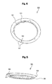
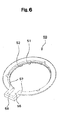
- the clamp 50 is not limited to the configuration shown in Figs. 4 and 5 in which a portion of the ring shape is simply cut off to provide the slit 56.
- the end portions 57 may be connected to each other by a connecting portion 58 which protrudes outward from the ring shape in a radial direction.
- the O-ring 70 may be configured such that a portion of the ring shape is cut off to provide a slit 71, and the end portions 72 separated by the slit 71 are connected to each other by a connecting portion 73 which protrudes outward from the ring shape in a radial direction.
- the magnetic disk drive 1 may include a plurality of magnetic disks 20 instead of one.
Landscapes
- Holding Or Fastening Of Disk On Rotational Shaft (AREA)
- Motor Or Generator Frames (AREA)
Applications Claiming Priority (1)
| Application Number | Priority Date | Filing Date | Title |
|---|---|---|---|
| JP2005119989A JP4250610B2 (ja) | 2005-04-18 | 2005-04-18 | 磁気ディスク装置 |
Publications (2)
| Publication Number | Publication Date |
|---|---|
| EP1715480A2 true EP1715480A2 (fr) | 2006-10-25 |
| EP1715480A3 EP1715480A3 (fr) | 2009-01-07 |
Family
ID=36699137
Family Applications (1)
| Application Number | Title | Priority Date | Filing Date |
|---|---|---|---|
| EP06252105A Withdrawn EP1715480A3 (fr) | 2005-04-18 | 2006-04-18 | Lecteur de disque magnétique |
Country Status (4)
| Country | Link |
|---|---|
| US (1) | US7561377B2 (fr) |
| EP (1) | EP1715480A3 (fr) |
| JP (1) | JP4250610B2 (fr) |
| CN (1) | CN1855290A (fr) |
Families Citing this family (5)
| Publication number | Priority date | Publication date | Assignee | Title |
|---|---|---|---|---|
| US7855852B2 (en) * | 2007-02-23 | 2010-12-21 | Seagate Technology Llc | Clamping system for a data storage device |
| US10119662B2 (en) | 2009-04-28 | 2018-11-06 | Cree, Inc. | Lens with controlled light refraction |
| CN103455239A (zh) * | 2012-06-04 | 2013-12-18 | 联想(北京)有限公司 | 一种信息提供方法及装置 |
| US9757912B2 (en) | 2014-08-27 | 2017-09-12 | Cree, Inc. | One-piece multi-lens optical member with ultraviolet inhibitor and method of manufacture |
| US9153282B1 (en) | 2015-05-01 | 2015-10-06 | Seagate Technology Llc | Disc clamp assembly with interlocking shims |
Family Cites Families (20)
| Publication number | Priority date | Publication date | Assignee | Title |
|---|---|---|---|---|
| US5367418A (en) * | 1992-11-13 | 1994-11-22 | Maxtor Corporation | Spin motor assembly that contains an O-ring which supports a disk in both the radial and axial directions |
| US5459627A (en) * | 1993-11-16 | 1995-10-17 | Hewlett-Packard Company | Disk drive having an O-ring disk clamp |
| US5943184A (en) * | 1994-02-02 | 1999-08-24 | Mobile Storage Technology, Inc. | Disk drive with a flat annular spring clamp and components dimensioned to maintain disk flatness |
| JPH07262748A (ja) | 1994-03-17 | 1995-10-13 | Fujitsu Ltd | 記憶装置の記録媒体取付構造 |
| US5493462A (en) * | 1994-06-03 | 1996-02-20 | Hewlett-Packard Company | Disk drive having an inwardly radially spring loaded hard ring disk pack attachment to the disk motor rotor |
| US5559651A (en) * | 1995-04-12 | 1996-09-24 | Seagate Technology, Inc. | Magnetic disc storage system with hydrodynamic bearing |
| JPH08297944A (ja) | 1995-04-26 | 1996-11-12 | Nec Corp | 焼きばめ媒体固定装置 |
| JPH08321107A (ja) | 1995-05-22 | 1996-12-03 | Miyota Kk | ハードディスクドライブのディスククランプ機構 |
| JPH09106622A (ja) | 1995-10-13 | 1997-04-22 | Hitachi Ltd | 磁気ディスク装置およびその製造方法 |
| JPH09115234A (ja) | 1995-10-19 | 1997-05-02 | Hitachi Ltd | 磁気ディスク装置のスピンドル構造及び磁気ディスク装置 |
| JPH09115216A (ja) | 1995-10-19 | 1997-05-02 | Hitachi Ltd | 磁気ディスク装置のスピンドル構造及び磁気ディスク装置 |
| JPH09115236A (ja) | 1995-10-19 | 1997-05-02 | Hitachi Ltd | 磁気ディスク装置及びその製造方法 |
| JPH09120610A (ja) | 1995-10-25 | 1997-05-06 | Hitachi Ltd | 磁気ディスク装置およびその組立て方法 |
| US5781374A (en) * | 1995-12-18 | 1998-07-14 | Seagate Technology, Inc. | Disc centering device for a disc drive |
| JP2001148187A (ja) | 1999-11-22 | 2001-05-29 | Fujitsu Ltd | ディスククランプ |
| US6624968B1 (en) * | 2000-07-13 | 2003-09-23 | Maxtor Corporation | Spring disk clamp utilizing wedged retaining ring |
| US6816338B1 (en) * | 2001-07-09 | 2004-11-09 | Maxtor Corporation | Disk clamp with one or more load distributing, balancing and/or stabilizing grooves |
| JP2004118935A (ja) | 2002-09-26 | 2004-04-15 | Soode Nagano Co Ltd | 磁気ディスクのクランプ機構 |
| JP2004335046A (ja) | 2003-05-12 | 2004-11-25 | Crd Kk | 止め具、ハブ及びそれらを用いたハードディスク取付構造 |
| JP4057567B2 (ja) | 2004-07-28 | 2008-03-05 | シーアールディ株式会社 | ハードディスクの固定装置およびその固定部材 |
-
2005
- 2005-04-18 JP JP2005119989A patent/JP4250610B2/ja not_active Expired - Fee Related
-
2006
- 2006-04-11 US US11/403,133 patent/US7561377B2/en not_active Expired - Fee Related
- 2006-04-17 CN CNA2006100752206A patent/CN1855290A/zh active Pending
- 2006-04-18 EP EP06252105A patent/EP1715480A3/fr not_active Withdrawn
Also Published As
| Publication number | Publication date |
|---|---|
| US7561377B2 (en) | 2009-07-14 |
| JP2006302359A (ja) | 2006-11-02 |
| JP4250610B2 (ja) | 2009-04-08 |
| CN1855290A (zh) | 2006-11-01 |
| EP1715480A3 (fr) | 2009-01-07 |
| US20060232881A1 (en) | 2006-10-19 |
Similar Documents
| Publication | Publication Date | Title |
|---|---|---|
| US5666243A (en) | Spring loaded stacked actuator assembly | |
| US8488270B2 (en) | Disk drive having a sheet metal clamp with a stamped annular protruding disk contact feature | |
| US5590004A (en) | Resilient clamp and compliant element data disk support system | |
| US8032903B2 (en) | Motor with a chucking device for detachably holding a disk and disk drive apparatus equipped with the same | |
| US6567238B1 (en) | Disc clamp for a disc drive | |
| US6417988B1 (en) | Disc clamp for a disc drive | |
| KR100834334B1 (ko) | 디스크 구동 장치 | |
| JP4553955B2 (ja) | ディスク回転駆動装置のクランプ及びクランプ製造方法 | |
| US5000589A (en) | Bearing structures for motors | |
| US20090161253A1 (en) | Bearing mechanism, motor and storage disk drive apparatus | |
| US8035917B2 (en) | Disk device having hub with engaging groove | |
| US6822826B2 (en) | Disc fixing apparatus and associated method fixing a disc and motor in balanced rotation | |
| EP1715480A2 (fr) | Lecteur de disque magnétique | |
| US7027261B2 (en) | Disk apparatus having an improved clamp structure | |
| US7054111B2 (en) | Disk drive actuator-pivot assembly with corrugated rings | |
| EP1560212B1 (fr) | Dispositif de maintien de disque et entraînement de disque dur comprenant un tel dispositif | |
| US20040136629A1 (en) | Bearing device | |
| US20080019039A1 (en) | Self-centering clamp | |
| US6339516B1 (en) | Disc drive deflected disc clamp lapping process | |
| KR20030051203A (ko) | 디스크 클램프 기구 | |
| US7545601B2 (en) | Magnetic disk drive with line contact | |
| US20030174440A1 (en) | Disc media retainer | |
| US20100134924A1 (en) | Storage device | |
| US9196292B1 (en) | Rotary spindle having a disk clamp bottom land facing and in contact with a shaft top land | |
| US10460758B2 (en) | Disk clamping mechanism including annular ring member |
Legal Events
| Date | Code | Title | Description |
|---|---|---|---|
| PUAI | Public reference made under article 153(3) epc to a published international application that has entered the european phase |
Free format text: ORIGINAL CODE: 0009012 |
|
| AK | Designated contracting states |
Kind code of ref document: A2 Designated state(s): AT BE BG CH CY CZ DE DK EE ES FI FR GB GR HU IE IS IT LI LT LU LV MC NL PL PT RO SE SI SK TR |
|
| AX | Request for extension of the european patent |
Extension state: AL BA HR MK YU |
|
| PUAL | Search report despatched |
Free format text: ORIGINAL CODE: 0009013 |
|
| AK | Designated contracting states |
Kind code of ref document: A3 Designated state(s): AT BE BG CH CY CZ DE DK EE ES FI FR GB GR HU IE IS IT LI LT LU LV MC NL PL PT RO SE SI SK TR |
|
| AX | Request for extension of the european patent |
Extension state: AL BA HR MK YU |
|
| AKX | Designation fees paid |
Designated state(s): DE FR GB |
|
| STAA | Information on the status of an ep patent application or granted ep patent |
Free format text: STATUS: THE APPLICATION IS DEEMED TO BE WITHDRAWN |
|
| 18D | Application deemed to be withdrawn |
Effective date: 20090708 |