EP1715497A2 - Dispositif de commande pourvu d'un tapis sensible - Google Patents
Dispositif de commande pourvu d'un tapis sensible Download PDFInfo
- Publication number
- EP1715497A2 EP1715497A2 EP06111973A EP06111973A EP1715497A2 EP 1715497 A2 EP1715497 A2 EP 1715497A2 EP 06111973 A EP06111973 A EP 06111973A EP 06111973 A EP06111973 A EP 06111973A EP 1715497 A2 EP1715497 A2 EP 1715497A2
- Authority
- EP
- European Patent Office
- Prior art keywords
- switching mat
- mat
- operating device
- switching
- stop
- Prior art date
- Legal status (The legal status is an assumption and is not a legal conclusion. Google has not performed a legal analysis and makes no representation as to the accuracy of the status listed.)
- Granted
Links
Images
Classifications
-
- H—ELECTRICITY
- H01—ELECTRIC ELEMENTS
- H01H—ELECTRIC SWITCHES; RELAYS; SELECTORS; EMERGENCY PROTECTIVE DEVICES
- H01H13/00—Switches having rectilinearly-movable operating part or parts adapted for pushing or pulling in one direction only, e.g. push-button switch
- H01H13/70—Switches having rectilinearly-movable operating part or parts adapted for pushing or pulling in one direction only, e.g. push-button switch having a plurality of operating members associated with different sets of contacts, e.g. keyboard
- H01H13/702—Switches having rectilinearly-movable operating part or parts adapted for pushing or pulling in one direction only, e.g. push-button switch having a plurality of operating members associated with different sets of contacts, e.g. keyboard with contacts carried by or formed from layers in a multilayer structure, e.g. membrane switches
- H01H13/705—Switches having rectilinearly-movable operating part or parts adapted for pushing or pulling in one direction only, e.g. push-button switch having a plurality of operating members associated with different sets of contacts, e.g. keyboard with contacts carried by or formed from layers in a multilayer structure, e.g. membrane switches characterised by construction, mounting or arrangement of operating parts, e.g. push-buttons or keys
-
- H—ELECTRICITY
- H01—ELECTRIC ELEMENTS
- H01H—ELECTRIC SWITCHES; RELAYS; SELECTORS; EMERGENCY PROTECTIVE DEVICES
- H01H13/00—Switches having rectilinearly-movable operating part or parts adapted for pushing or pulling in one direction only, e.g. push-button switch
- H01H13/02—Details
- H01H13/12—Movable parts; Contacts mounted thereon
- H01H13/14—Operating parts, e.g. push-button
-
- H—ELECTRICITY
- H01—ELECTRIC ELEMENTS
- H01H—ELECTRIC SWITCHES; RELAYS; SELECTORS; EMERGENCY PROTECTIVE DEVICES
- H01H9/00—Details of switching devices, not covered by groups H01H1/00 - H01H7/00
- H01H9/02—Bases, casings, or covers
- H01H2009/0278—Casings containing special noise reduction means, e.g. elastic foam between inner and outer casing
-
- H—ELECTRICITY
- H01—ELECTRIC ELEMENTS
- H01H—ELECTRIC SWITCHES; RELAYS; SELECTORS; EMERGENCY PROTECTIVE DEVICES
- H01H2233/00—Key modules
- H01H2233/01—Key modules mounted on laykey
- H01H2233/014—Snap coupling
- H01H2233/016—Snap coupling with limited freedom
-
- H—ELECTRICITY
- H01—ELECTRIC ELEMENTS
- H01H—ELECTRIC SWITCHES; RELAYS; SELECTORS; EMERGENCY PROTECTIVE DEVICES
- H01H2237/00—Mechanism between key and laykey
- H01H2237/008—Plunger guided by flexible arms
Definitions
- the invention relates to an operating device with at least one arranged in a panel and guided pushbutton and a switching mat, wherein the push button acts in an actuating position for closing an electrical contact on one of the panel facing side of the switching mat and rests in a rest position on a stop.
- Such an operating device is for example from the DE 197 25 486 A1 known.
- a push button which is arranged in a diaphragm, with a dome-shaped protuberance of a switching mat in contact.
- the switching mat is arranged on a circuit board having two contact points.
- the dome-shaped protuberance of the switching mat has on the circuit board side facing a contact bridge, so that when depressing the dome-shaped protuberance of the switching mat by the push button, the two contacts are electrically connected to each other and thus closed.
- the button In a rest position, the button is located on a guide frame belonging to the panel.
- the object of the invention is therefore to provide an operating device in which a sound largely when the button recovers from the operating position to the rest position is avoided.
- the object is achieved by an operating device with the features of claim 1.
- the invention provides to share the already existing switching mat for the purpose of noise reduction and this purpose to form the stop on which the button is in the rest position, by a side facing away from the panel side of the switching mat.
- the operating device according to the invention thus proposes the key when rewinding from the operating position in the rest position on the keypad.
- a known switching mat In a generic control device, a known switching mat is used.
- the safety mat consists essentially of a rubber-elastic material. This elasticity allows, for example, domed protuberances of the switching mat on which the button acts to depress the triggering of the switching process and at the same time ensures that the switching mat returns to its original shape when relieved. If the key strikes the backrest from the operating position in the rest position on such a rubber-elastic material, this results in almost no noise.
- the switching mat rests in the region of the stop on the panel.
- the switching mat in the region of the stop but with the side facing the diaphragm, directly to a portion of the diaphragm, while the corresponding opposite, facing away from the panel area, serves as a stop for the button.
- the key has at least one shaft which engages around the switching mat, a partial region of the shaft engaging behind the switching mat abutting against the stop in the rest position.
- the shaft can, for example, surround the edge region of a switching mat, wherein, for example, a partial region designed in the form of a latching nose engages behind the switching mat and bears against the switching mat in the rest position.
- the switching mat has a recess through which the shaft protrudes.
- This embodiment is particularly advantageous when the operating device has a plurality of push buttons which act on the switching mat. If the shank protrudes through the recess of the switching mat, the partial area which engages behind the switching mat can rest against the side of the switching mat remote from the screen in the rest position. Since the recess can be arranged almost anywhere within the switching mat, a large freedom in terms of design and arrangement of the push button is achieved with this configuration. Since the switching mat usually rests on a large printed circuit board, in this embodiment, the circuit board will have a corresponding recess into which the shaft can at least protrude, and does not hinder the movement of the shaft even when pressing the push button.
- the switching mat has fixing openings, protrude into the fixing pins. As a result, a simple positioning of the switching mat and diaphragm or push button to each other is achieved.
- the fixing pins are arranged in particular directly on the panel, for example on the guides for the push button and project into correspondingly adapted fixing openings of the switching mat. In addition to the fixing of the switching mat relative to the panel and pushbutton during assembly thereby in particular a lateral slippage of the switching mat and thus the stop is prevented.
- the operating device according to the invention can be used particularly advantageously as a motor vehicle component, for example for operating an information and / or entertainment device, an air conditioning system, a hazard warning system, a rear window heater and the like.
- the operating device according to the invention can also be used in devices in the domestic or industrial sector.
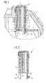
- Figure 1 shows a section through an operating device according to the invention with a button 1, which acts on a switching mat 2 and is arranged and guided in a panel 3.
- a button 1 which acts on a switching mat 2 and is arranged and guided in a panel 3.
- controls are arranged, which act at least partially also on the switching mat 2.
- the panel 3 has side walls 4 which guide the key 1.
- the button 1 acts on a dome-shaped protuberance 5 of the switching mat 2, wherein upon pressure of an operator on the surface 6 of the button 1, the protuberance 5 is compressed by the key 1. This closes a contact bridge. 7 Contacts on a printed circuit board, not shown here, on which the switching mat 2 rests. In this respect, it is the usual operation of a known pressure switch.
- the switching mat 2 now also has a recess 8 through which a shaft 9 protrudes.
- the shaft 9 has a latch-like portion 11 which engages behind the switching mat 2 and in the rest position shown in Figure 1 abuts against a stop 12 which is formed by the side facing away from the panel 3 side 10 of the switching mat 2.
- the stop 12 is thus according to the invention part of the switching mat 2 and therefore consists of a rubber-elastic material.
- the switching mat 2 is in the region of the stop 12 with the side facing the panel 13 on the wall 4, which is part of the panel 3.
- the wall 4 of the diaphragm 2 also has fixing pins, not shown, in the likewise not shown, adapted to the dimensions of the fixing pins fixing holes of Protect switching mat 2 and thus fix the keypad against the panel and the button.
- the pushbutton 1 has a first shaft 9a and a second shaft 9b, which respectively have partial regions 11a, 11b which are formed like latching noses ,
- the first shaft 9a and the second shaft 9b protrude in the manner shown in Figure 1 through an opening of the switching mat 2, wherein the portions 11a, 11b respectively abut against a stop 12 of the switching mat.
- a single shaft 9 is sufficient.
- the surface 14 of the key 1 acts on the switching mat 2 for generating the switching operation.
- the invention has been described with reference to an embodiment with a recess in the switching mat through which the shaft of the button protrudes.
- the shank may also surround the edge of the switching mat, wherein, for example, the latching nose-like partial regions 11a, 11b shown in FIG. 2 are directed inwards and thus encompass a switching mat arranged between the first and second shafts 9a, 9b.
Landscapes
- Push-Button Switches (AREA)
Applications Claiming Priority (1)
| Application Number | Priority Date | Filing Date | Title |
|---|---|---|---|
| DE200510017852 DE102005017852B3 (de) | 2005-04-18 | 2005-04-18 | Bedienvorrichtung mit einer Schaltmatte |
Publications (3)
| Publication Number | Publication Date |
|---|---|
| EP1715497A2 true EP1715497A2 (fr) | 2006-10-25 |
| EP1715497A3 EP1715497A3 (fr) | 2007-11-14 |
| EP1715497B1 EP1715497B1 (fr) | 2014-01-01 |
Family
ID=36616762
Family Applications (1)
| Application Number | Title | Priority Date | Filing Date |
|---|---|---|---|
| EP20060111973 Ceased EP1715497B1 (fr) | 2005-04-18 | 2006-03-30 | Dispositif de commande pourvu d'un tapis sensible |
Country Status (2)
| Country | Link |
|---|---|
| EP (1) | EP1715497B1 (fr) |
| DE (1) | DE102005017852B3 (fr) |
Cited By (2)
| Publication number | Priority date | Publication date | Assignee | Title |
|---|---|---|---|---|
| CN111640611A (zh) * | 2019-03-01 | 2020-09-08 | 广州艾美网络科技有限公司 | 旋钮式按键结构、电路控制结构、设备和控制方法 |
| EP4179951A1 (fr) * | 2021-11-10 | 2023-05-17 | Ambu A/S | Bouton de commutation pour endoscope |
Citations (2)
| Publication number | Priority date | Publication date | Assignee | Title |
|---|---|---|---|---|
| GB2255234A (en) | 1991-03-27 | 1992-10-28 | Hitachi Telecomm Tech | Keyboards. |
| DE19726486A1 (de) | 1997-06-21 | 1998-12-24 | Mannesmann Vdo Ag | Schaltelement |
Family Cites Families (5)
| Publication number | Priority date | Publication date | Assignee | Title |
|---|---|---|---|---|
| US3928741A (en) * | 1974-09-16 | 1975-12-23 | Texas Instruments Inc | Momentary contact single pole switch |
| US4181826A (en) * | 1978-04-06 | 1980-01-01 | Motorola, Inc. | Dome switch actuating apparatus |
| US4334134A (en) * | 1980-11-13 | 1982-06-08 | Gte Automatic Electric Labs Inc. | Identification cap actuator assembly |
| DE3114563C2 (de) * | 1981-04-10 | 1986-10-30 | Leopold Kostal GmbH & Co KG, 5880 Lüdenscheid | Drucktastenschalter |
| DE19628991C1 (de) * | 1996-07-18 | 1997-07-17 | Kostal Leopold Gmbh & Co Kg | Tastschalter |
-
2005
- 2005-04-18 DE DE200510017852 patent/DE102005017852B3/de not_active Expired - Fee Related
-
2006
- 2006-03-30 EP EP20060111973 patent/EP1715497B1/fr not_active Ceased
Patent Citations (2)
| Publication number | Priority date | Publication date | Assignee | Title |
|---|---|---|---|---|
| GB2255234A (en) | 1991-03-27 | 1992-10-28 | Hitachi Telecomm Tech | Keyboards. |
| DE19726486A1 (de) | 1997-06-21 | 1998-12-24 | Mannesmann Vdo Ag | Schaltelement |
Cited By (4)
| Publication number | Priority date | Publication date | Assignee | Title |
|---|---|---|---|---|
| CN111640611A (zh) * | 2019-03-01 | 2020-09-08 | 广州艾美网络科技有限公司 | 旋钮式按键结构、电路控制结构、设备和控制方法 |
| CN111640611B (zh) * | 2019-03-01 | 2025-08-12 | 广州艾美网络科技有限公司 | 旋钮式按键结构、电路控制结构、设备和控制方法 |
| EP4179951A1 (fr) * | 2021-11-10 | 2023-05-17 | Ambu A/S | Bouton de commutation pour endoscope |
| US12504617B2 (en) | 2021-11-10 | 2025-12-23 | Ambu A/S | Switch button for an endoscope |
Also Published As
| Publication number | Publication date |
|---|---|
| EP1715497A3 (fr) | 2007-11-14 |
| DE102005017852B3 (de) | 2006-10-12 |
| EP1715497B1 (fr) | 2014-01-01 |
Similar Documents
| Publication | Publication Date | Title |
|---|---|---|
| DE3032557C2 (de) | Gummielastisches Tastkontaktelement | |
| EP2979289B1 (fr) | Poussoir à touche d'un module à touche pour un clavier, un module à tocuhe pour un clavier et procédé de fabrication d'un module à touche pour une touche pour un clavier | |
| DE112013004270B4 (de) | Schaltersteuerelement für schalter und drucktaste mit einem solchen schaltersteuerelement | |
| EP1736354A2 (fr) | Organe de commande à détecteur de proximité | |
| EP3078046A1 (fr) | Clavier pourvu de plusieurs touches stabilisées en forme de plaque | |
| DE19634051C1 (de) | Schalteranordnung mit mindestens einer Drucktaste | |
| DE4312771C2 (de) | Zweistufentaster | |
| DE102017003246A1 (de) | Bedienvorrichtung mit druckempfindlichem Tastschalter | |
| EP1715497B1 (fr) | Dispositif de commande pourvu d'un tapis sensible | |
| DE2439697B2 (de) | Druckschalter | |
| EP1467390B1 (fr) | Clavier à touches pour le panneau de commande des appareils électro-domestiques | |
| DE3928650A1 (de) | Elektrischer druckschalter | |
| DE10309516B3 (de) | Tastenblock mit Federgeometrie | |
| WO2015074813A1 (fr) | Touche, commutateur de touche, cadre de touche et carte de circuits imprimés pour dispositif de saisie de données, dispositif de saisie de données et procédé permettant de réduire le trajet de commutation d'un commutateur de touche d'un dispositif de saisie de données | |
| DE19836793C2 (de) | Bedienelement zum selektiven Herstellen elektrischer Kontakte | |
| EP1482527B1 (fr) | Interrupteur à bouton poussoir | |
| DE102005033166B4 (de) | Schaltapparat mit wenigstens einem Schaltstößel | |
| DE19621192A1 (de) | Niederspannungsschaltgerät | |
| EP0401544A2 (fr) | Touche pour un clavier | |
| EP2487699B1 (fr) | Bouton-poussoir à faible course | |
| DE102020131445B4 (de) | Bedienvorrichtung | |
| DE10340329B4 (de) | Bedienschalteranordnung | |
| DE102009058615B4 (de) | Schaltervorrichtung | |
| DE19627213C1 (de) | Betätigungseinheit für ein elektrisches Gerät | |
| DE10349592B4 (de) | Tastenblock zum Einsetzen in eine Blende und Montageanordnung eines Tastenblocks an einer Blende |
Legal Events
| Date | Code | Title | Description |
|---|---|---|---|
| PUAI | Public reference made under article 153(3) epc to a published international application that has entered the european phase |
Free format text: ORIGINAL CODE: 0009012 |
|
| AK | Designated contracting states |
Kind code of ref document: A2 Designated state(s): AT BE BG CH CY CZ DE DK EE ES FI FR GB GR HU IE IS IT LI LT LU LV MC NL PL PT RO SE SI SK TR |
|
| AX | Request for extension of the european patent |
Extension state: AL BA HR MK YU |
|
| PUAL | Search report despatched |
Free format text: ORIGINAL CODE: 0009013 |
|
| AK | Designated contracting states |
Kind code of ref document: A3 Designated state(s): AT BE BG CH CY CZ DE DK EE ES FI FR GB GR HU IE IS IT LI LT LU LV MC NL PL PT RO SE SI SK TR |
|
| AX | Request for extension of the european patent |
Extension state: AL BA HR MK YU |
|
| RIC1 | Information provided on ipc code assigned before grant |
Ipc: H01H 13/705 20060101ALI20071009BHEP Ipc: H01H 13/14 20060101AFI20060711BHEP |
|
| 17P | Request for examination filed |
Effective date: 20071214 |
|
| 17Q | First examination report despatched |
Effective date: 20080204 |
|
| RAP1 | Party data changed (applicant data changed or rights of an application transferred) |
Owner name: CONTINENTAL AUTOMOTIVE GMBH |
|
| AKX | Designation fees paid |
Designated state(s): DE FR GB IT |
|
| REG | Reference to a national code |
Ref country code: DE Ref legal event code: R079 Ref document number: 502006013470 Country of ref document: DE Free format text: PREVIOUS MAIN CLASS: H01H0013140000 Ipc: H01H0009020000 |
|
| RIC1 | Information provided on ipc code assigned before grant |
Ipc: H01H 13/705 20060101ALI20130607BHEP Ipc: H01H 13/14 20060101ALI20130607BHEP Ipc: H01H 9/02 20060101AFI20130607BHEP |
|
| GRAP | Despatch of communication of intention to grant a patent |
Free format text: ORIGINAL CODE: EPIDOSNIGR1 |
|
| INTG | Intention to grant announced |
Effective date: 20130726 |
|
| GRAS | Grant fee paid |
Free format text: ORIGINAL CODE: EPIDOSNIGR3 |
|
| GRAA | (expected) grant |
Free format text: ORIGINAL CODE: 0009210 |
|
| AK | Designated contracting states |
Kind code of ref document: B1 Designated state(s): DE FR GB IT |
|
| REG | Reference to a national code |
Ref country code: GB Ref legal event code: FG4D Free format text: NOT ENGLISH |
|
| REG | Reference to a national code |
Ref country code: DE Ref legal event code: R096 Ref document number: 502006013470 Country of ref document: DE Effective date: 20140220 |
|
| REG | Reference to a national code |
Ref country code: DE Ref legal event code: R097 Ref document number: 502006013470 Country of ref document: DE |
|
| PLBE | No opposition filed within time limit |
Free format text: ORIGINAL CODE: 0009261 |
|
| STAA | Information on the status of an ep patent application or granted ep patent |
Free format text: STATUS: NO OPPOSITION FILED WITHIN TIME LIMIT |
|
| 26N | No opposition filed |
Effective date: 20141002 |
|
| GBPC | Gb: european patent ceased through non-payment of renewal fee |
Effective date: 20140401 |
|
| REG | Reference to a national code |
Ref country code: DE Ref legal event code: R097 Ref document number: 502006013470 Country of ref document: DE Effective date: 20141002 |
|
| PG25 | Lapsed in a contracting state [announced via postgrant information from national office to epo] |
Ref country code: GB Free format text: LAPSE BECAUSE OF NON-PAYMENT OF DUE FEES Effective date: 20140401 |
|
| REG | Reference to a national code |
Ref country code: FR Ref legal event code: PLFP Year of fee payment: 11 |
|
| PG25 | Lapsed in a contracting state [announced via postgrant information from national office to epo] |
Ref country code: IT Free format text: LAPSE BECAUSE OF FAILURE TO SUBMIT A TRANSLATION OF THE DESCRIPTION OR TO PAY THE FEE WITHIN THE PRESCRIBED TIME-LIMIT Effective date: 20140101 |
|
| REG | Reference to a national code |
Ref country code: FR Ref legal event code: PLFP Year of fee payment: 12 |
|
| REG | Reference to a national code |
Ref country code: FR Ref legal event code: PLFP Year of fee payment: 13 |
|
| REG | Reference to a national code |
Ref country code: DE Ref legal event code: R084 Ref document number: 502006013470 Country of ref document: DE |
|
| REG | Reference to a national code |
Ref country code: DE Ref legal event code: R081 Ref document number: 502006013470 Country of ref document: DE Owner name: CONTINENTAL AUTOMOTIVE TECHNOLOGIES GMBH, DE Free format text: FORMER OWNER: CONTINENTAL AUTOMOTIVE GMBH, 30165 HANNOVER, DE |
|
| P01 | Opt-out of the competence of the unified patent court (upc) registered |
Effective date: 20230522 |
|
| REG | Reference to a national code |
Ref country code: DE Ref legal event code: R081 Ref document number: 502006013470 Country of ref document: DE Owner name: CONTINENTAL AUTOMOTIVE TECHNOLOGIES GMBH, DE Free format text: FORMER OWNER: CONTINENTAL AUTOMOTIVE TECHNOLOGIES GMBH, 30165 HANNOVER, DE |
|
| PGFP | Annual fee paid to national office [announced via postgrant information from national office to epo] |
Ref country code: DE Payment date: 20240331 Year of fee payment: 19 |
|
| PGFP | Annual fee paid to national office [announced via postgrant information from national office to epo] |
Ref country code: FR Payment date: 20240321 Year of fee payment: 19 |
|
| REG | Reference to a national code |
Ref country code: DE Ref legal event code: R119 Ref document number: 502006013470 Country of ref document: DE |
|
| PG25 | Lapsed in a contracting state [announced via postgrant information from national office to epo] |
Ref country code: DE Free format text: LAPSE BECAUSE OF NON-PAYMENT OF DUE FEES Effective date: 20251001 |
|
| PG25 | Lapsed in a contracting state [announced via postgrant information from national office to epo] |
Ref country code: FR Free format text: LAPSE BECAUSE OF NON-PAYMENT OF DUE FEES Effective date: 20250331 |