EP1715547A2 - Système modulaire avec pont connecteur pour une ligne de bus interne - Google Patents
Système modulaire avec pont connecteur pour une ligne de bus interne Download PDFInfo
- Publication number
- EP1715547A2 EP1715547A2 EP06110891A EP06110891A EP1715547A2 EP 1715547 A2 EP1715547 A2 EP 1715547A2 EP 06110891 A EP06110891 A EP 06110891A EP 06110891 A EP06110891 A EP 06110891A EP 1715547 A2 EP1715547 A2 EP 1715547A2
- Authority
- EP
- European Patent Office
- Prior art keywords
- module system
- modules
- clamping
- bridge elements
- legs
- Prior art date
- Legal status (The legal status is an assumption and is not a legal conclusion. Google has not performed a legal analysis and makes no representation as to the accuracy of the status listed.)
- Granted
Links
Images


Classifications
-
- H—ELECTRICITY
- H01—ELECTRIC ELEMENTS
- H01R—ELECTRICALLY-CONDUCTIVE CONNECTIONS; STRUCTURAL ASSOCIATIONS OF A PLURALITY OF MUTUALLY-INSULATED ELECTRICAL CONNECTING ELEMENTS; COUPLING DEVICES; CURRENT COLLECTORS
- H01R9/00—Structural associations of a plurality of mutually-insulated electrical connecting elements, e.g. terminal strips or terminal blocks; Terminals or binding posts mounted upon a base or in a case; Bases therefor
- H01R9/22—Bases, e.g. strip, block, panel
- H01R9/24—Terminal blocks
- H01R9/26—Clip-on terminal blocks for side-by-side rail- or strip-mounting
- H01R9/2675—Electrical interconnections between two blocks, e.g. by means of busbars
-
- H—ELECTRICITY
- H01—ELECTRIC ELEMENTS
- H01R—ELECTRICALLY-CONDUCTIVE CONNECTIONS; STRUCTURAL ASSOCIATIONS OF A PLURALITY OF MUTUALLY-INSULATED ELECTRICAL CONNECTING ELEMENTS; COUPLING DEVICES; CURRENT COLLECTORS
- H01R13/00—Details of coupling devices of the kinds covered by groups H01R12/70 or H01R24/00 - H01R33/00
- H01R13/62—Means for facilitating engagement or disengagement of coupling parts or for holding them in engagement
- H01R13/629—Additional means for facilitating engagement or disengagement of coupling parts, e.g. aligning or guiding means, levers, gas pressure electrical locking indicators, manufacturing tolerances
- H01R13/633—Additional means for facilitating engagement or disengagement of coupling parts, e.g. aligning or guiding means, levers, gas pressure electrical locking indicators, manufacturing tolerances for disengagement only
- H01R13/6335—Additional means for facilitating engagement or disengagement of coupling parts, e.g. aligning or guiding means, levers, gas pressure electrical locking indicators, manufacturing tolerances for disengagement only comprising a handle
-
- H—ELECTRICITY
- H01—ELECTRIC ELEMENTS
- H01R—ELECTRICALLY-CONDUCTIVE CONNECTIONS; STRUCTURAL ASSOCIATIONS OF A PLURALITY OF MUTUALLY-INSULATED ELECTRICAL CONNECTING ELEMENTS; COUPLING DEVICES; CURRENT COLLECTORS
- H01R4/00—Electrically-conductive connections between two or more conductive members in direct contact, i.e. touching one another; Means for effecting or maintaining such contact; Electrically-conductive connections having two or more spaced connecting locations for conductors and using contact members penetrating insulation
- H01R4/28—Clamped connections, spring connections
- H01R4/48—Clamped connections, spring connections utilising a spring, clip, or other resilient member
- H01R4/4809—Clamped connections, spring connections utilising a spring, clip, or other resilient member using a leaf spring to bias the conductor toward the busbar
- H01R4/48185—Clamped connections, spring connections utilising a spring, clip, or other resilient member using a leaf spring to bias the conductor toward the busbar adapted for axial insertion of a wire end
- H01R4/4819—Clamped connections, spring connections utilising a spring, clip, or other resilient member using a leaf spring to bias the conductor toward the busbar adapted for axial insertion of a wire end the spring shape allowing insertion of the conductor end when the spring is unbiased
- H01R4/4821—Single-blade spring
-
- H—ELECTRICITY
- H01—ELECTRIC ELEMENTS
- H01R—ELECTRICALLY-CONDUCTIVE CONNECTIONS; STRUCTURAL ASSOCIATIONS OF A PLURALITY OF MUTUALLY-INSULATED ELECTRICAL CONNECTING ELEMENTS; COUPLING DEVICES; CURRENT COLLECTORS
- H01R4/00—Electrically-conductive connections between two or more conductive members in direct contact, i.e. touching one another; Means for effecting or maintaining such contact; Electrically-conductive connections having two or more spaced connecting locations for conductors and using contact members penetrating insulation
- H01R4/28—Clamped connections, spring connections
- H01R4/48—Clamped connections, spring connections utilising a spring, clip, or other resilient member
- H01R4/4809—Clamped connections, spring connections utilising a spring, clip, or other resilient member using a leaf spring to bias the conductor toward the busbar
- H01R4/4828—Spring-activating arrangements mounted on or integrally formed with the spring housing
-
- H—ELECTRICITY
- H01—ELECTRIC ELEMENTS
- H01R—ELECTRICALLY-CONDUCTIVE CONNECTIONS; STRUCTURAL ASSOCIATIONS OF A PLURALITY OF MUTUALLY-INSULATED ELECTRICAL CONNECTING ELEMENTS; COUPLING DEVICES; CURRENT COLLECTORS
- H01R13/00—Details of coupling devices of the kinds covered by groups H01R12/70 or H01R24/00 - H01R33/00
- H01R13/62—Means for facilitating engagement or disengagement of coupling parts or for holding them in engagement
- H01R13/629—Additional means for facilitating engagement or disengagement of coupling parts, e.g. aligning or guiding means, levers, gas pressure electrical locking indicators, manufacturing tolerances
- H01R13/62933—Comprising exclusively pivoting lever
- H01R13/62966—Comprising two pivoting levers
-
- H—ELECTRICITY
- H01—ELECTRIC ELEMENTS
- H01R—ELECTRICALLY-CONDUCTIVE CONNECTIONS; STRUCTURAL ASSOCIATIONS OF A PLURALITY OF MUTUALLY-INSULATED ELECTRICAL CONNECTING ELEMENTS; COUPLING DEVICES; CURRENT COLLECTORS
- H01R31/00—Coupling parts supported only by co-operation with counterpart
- H01R31/08—Short-circuiting members for bridging contacts in a counterpart
-
- H—ELECTRICITY
- H01—ELECTRIC ELEMENTS
- H01R—ELECTRICALLY-CONDUCTIVE CONNECTIONS; STRUCTURAL ASSOCIATIONS OF A PLURALITY OF MUTUALLY-INSULATED ELECTRICAL CONNECTING ELEMENTS; COUPLING DEVICES; CURRENT COLLECTORS
- H01R4/00—Electrically-conductive connections between two or more conductive members in direct contact, i.e. touching one another; Means for effecting or maintaining such contact; Electrically-conductive connections having two or more spaced connecting locations for conductors and using contact members penetrating insulation
- H01R4/28—Clamped connections, spring connections
- H01R4/48—Clamped connections, spring connections utilising a spring, clip, or other resilient member
- H01R4/4809—Clamped connections, spring connections utilising a spring, clip, or other resilient member using a leaf spring to bias the conductor toward the busbar
- H01R4/4846—Busbar details
-
- H—ELECTRICITY
- H01—ELECTRIC ELEMENTS
- H01R—ELECTRICALLY-CONDUCTIVE CONNECTIONS; STRUCTURAL ASSOCIATIONS OF A PLURALITY OF MUTUALLY-INSULATED ELECTRICAL CONNECTING ELEMENTS; COUPLING DEVICES; CURRENT COLLECTORS
- H01R9/00—Structural associations of a plurality of mutually-insulated electrical connecting elements, e.g. terminal strips or terminal blocks; Terminals or binding posts mounted upon a base or in a case; Bases therefor
- H01R9/22—Bases, e.g. strip, block, panel
- H01R9/24—Terminal blocks
- H01R9/26—Clip-on terminal blocks for side-by-side rail- or strip-mounting
- H01R9/2625—Clip-on terminal blocks for side-by-side rail- or strip-mounting with built-in electrical component
- H01R9/2658—Clip-on terminal blocks for side-by-side rail- or strip-mounting with built-in electrical component with built-in data-bus connection
Definitions
- the invention relates to a bus module system consisting of modules which can be connected to one another according to the preamble of claim 1.
- Bus module systems of modules which can be connected to one another are known from the prior art in a wide variety of embodiments, as shown in FIG DE 299 16 303 U1 or the EP 95 113 730 A1 ,
- such a bus module system consists of a gateway and further modules connected thereto, whereby by means of an electronic circuit a signal adaptation takes place between a higher-level fieldbus system and the field devices connectable to the modules, such as actuators, initiators or the like.
- the modules are similar to terminal blocks on mounting rails latched and lined up.
- an internal bus conductor with one or more bus wires, wherein the bus conductors of the mutually adjacent modules in the juxtaposition of the modules must be connected to each other.
- Such an internal bus conductor comprises any number of supply and / or signal or data lines.
- the invention has the object to realize a connection of adjacent modules, which should be to be solved again in particular when using a tool-free connection technology in a simple manner.
- a reliable mechanical connection of adjacent modules without further operations are realized.
- connection devices are each designed as direct plug-in terminals with clamping springs for tool-free wiring with the conductive bridge elements and at the connecting bridge is at least one unlocking device for releasing a plurality of the conductive bridge elements from the respectively associated clamping springs of the connection devices arranged.
- This solution offers the advantage of simple wiring through the use of direct plug-in terminals and a compact connection bridge and the tool-free release or disconnection by means of a cross-release device for preferably all terminal points one side of the juxtaposed and interconnected modules.
- the unlocking device has at least one or two pivotable swing paddles for direct or indirect action on the clamping springs.
- two longitudinal legs of the shackle rockers are on cams on the modules about which they are pivotable.
- the cams for supporting the paddle shafts on the modules are arranged such that in addition to the release of the bridge elements from the clamping points and a lifting of the conductive bridge elements from the terminal points takes place.
- Such a double function is advantageously realized, which includes both the release of the conductive bridge elements in the terminal points and at the same time lifting the conductive bridge elements from the terminal points, which simplifies handling when switching off with a movement in one direction.
- the invention is complemented by at least one profile web extending preferably parallel to the longitudinal limbs of the bridge elements, which engages in recesses in the adjacent modules, so that a mechanical, the arrangement stabilizing positive engagement between the adjacent modules is realized.
- the profile web is provided on two opposite sides each with a groove profile, wherein each one of the groove profiles engages in a correspondingly shaped NutausEnglishung of one of the two adjacent modules, so that a double tongue and groove connection between the modules and the profile web a stable complementary positive connection between the adjacent modules is realized without the need for further operations.
- the bus bridge can not only be used as a pure transfer or transit of bus signals or the power supply, but also optionally also accommodate additional electronic components such as: fuses (for protection against incorrect operation), LEDs (for example for status display or reset). Furthermore, any other electrical functions can also be integrated into the component.
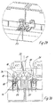
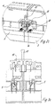
- the figures each show two adjacent modules 1, 2, which may be designed, for example, to be snapped onto a mounting rail (not shown here) and e.g. consist of a base support 3 and an electronics housing 4 mounted thereon.
- each module 1, 2 extends an internal bus conductor (not fully shown here), which consists of several preferably parallel to each other conductors 21 (only in Fig. 2a), to each of which a terminal device is connected at both ends of each module here is designed here as a tool-free direct plug-in terminal 5, which are arranged side by side in a row.
- the direct male terminals 5 - see Fig. 3a - 3c - each consist of a metal cage open on one side 6, which can also act as a busbar and arranged in a metal cage 6 u- or v-shaped clamping spring 7, one leg 8 is fixed to the metal cage 6 and whose other leg serves as clamping leg 9, with which a conductor 10 with pressure inside against the metal cage 6 or a bus bar on the metal cage can be pressed to realize an electrical contact between the conductor 10 and the metal cage 6 and / or a separate busbar, which in turn is conductively connected to the internal bus conductor 21.
- a higher-level connection bridge 11 is used for connecting the plurality of connection devices of adjacent modules 1, 2.
- This connecting bridge 11 consists on the one hand of a plurality of conductive, preferably U-shaped bridge elements 12 of busbars, which are aligned parallel to each other on a plate-like base body 13 with a handle 17 are arranged.
- the individual conductive bridge elements 12 each serve to connect two connection devices of adjacent modules 1, 2.
- the mutually parallel longitudinal legs 14 of the bridge elements 12 are spaced apart and arranged such that the free ends of the longitudinal legs 14 (in the exemplary position of Fig. 1) can be pressed from the top tool-free in the Ministeckklemmen 5, wherein the clamping legs 9 aside to press, so that a conductive connection is realized in the clamping points 20 to the metal cage 6.
- a mechanical connection between the adjacent modules 1, 2 is realized, by means of positive engagement via a parallel to the longitudinal legs 14 of the bridge elements extending profile web 15 (see in particular Fig. 1), which is here centrally between the longitudinal legs 14 and is provided on two opposite sides each with a groove profile 16, wherein each one of the groove profiles 16 engages in a correspondingly shaped NutausANSung 27 of one of the two adjacent modules 1, 2, so that a double tongue and groove connection between the modules 1, 2 and the profile web 15 a complementary mechanical positive connection between the adjacent modules 1, 2 is realized.
- This tongue and groove joint is a mechanical stabilizing option and may be of any shape. In addition, it can take over a coding function if different modules have different groove shapes (not shown here).
- each connecting device 6 is assigned to one of the pressing elements 18.
- These pressing elements 18 are movably mounted in the clamping or metal cage 6 above the clamping legs 9 in the conductor insertion direction (perpendicular in the exemplary position of use of FIG. 1) and act on the clamping legs 9 in order to disengage them from the longitudinal legs 14 of the bridge elements 12 to solve.
- the rocker arms 19 are pivotally mounted on the base body 13 on two opposite sides of the body, which also have a U-shape in plan view and the base body 13 laterally from opposite sides of the modules 1, 2 ago ,
- the two longitudinal legs 23 of this bracket rockers 19 are pivotally mounted on the sides of the base body 13.
- the base legs 24 of the swing jacks are arranged above the pressing elements 18 (FIGS. 2 a, 3 a), so that upon depression of the swing jacks 19, the base legs 24 of the same directly or as shown here via lower cam 25 the Press actuating push button 18 in the direction of the clamping legs, whereby the conductor 10 or longitudinal legs 14 in the clamping points 20 are cowards (Fig. 2b, 3b).
- the longitudinal legs 23 of the shackle rockers are stepped in or L-shaped, wherein the second cam 26 as a pivot bearing at a lower point on the module housing of the modules 1, 2 than the first cam 25 on the actuating levers 18th pivot bearing are thus the second Cam 26, while the first cam 25 act as actuation lugs for the actuating handle 18.
- the shackle rockers 19 realize both the release of the bridge elements 12 from the clamping points 20 and the disengagement and the lifting of the bridge elements 12 from the clamping points 20. They thus provide an overall unlocking device for the conductors in the clamping points 20 of the connection devices one end of the internal bus conductor of a module 1, 2 represents.
- the ironing jacks 19 can only take over the de-switching function. It is conceivable, for example, that the mounting of the bow-type rockers 19 does not take place in each case on two cams 25, 26 but that they coincide in a single cam (not shown here).
- the function of the separate actuating push-button 18 can also be integrated into this with appropriate design of the first cam.
- the first cams 25 would then extend directly to the clamping points (not shown here).
Landscapes
- Details Of Connecting Devices For Male And Female Coupling (AREA)
- Installation Of Bus-Bars (AREA)
- Connections Arranged To Contact A Plurality Of Conductors (AREA)
Applications Claiming Priority (1)
| Application Number | Priority Date | Filing Date | Title |
|---|---|---|---|
| DE202005006237U DE202005006237U1 (de) | 2005-04-18 | 2005-04-18 | Busmodulsystem mit Verbindungsbrücke für einen internen Busleiter |
Publications (3)
| Publication Number | Publication Date |
|---|---|
| EP1715547A2 true EP1715547A2 (fr) | 2006-10-25 |
| EP1715547A3 EP1715547A3 (fr) | 2008-04-16 |
| EP1715547B1 EP1715547B1 (fr) | 2015-04-22 |
Family
ID=36644881
Family Applications (1)
| Application Number | Title | Priority Date | Filing Date |
|---|---|---|---|
| EP20060110891 Expired - Lifetime EP1715547B1 (fr) | 2005-04-18 | 2006-03-09 | Système modulaire avec pont connecteur pour une ligne de bus interne |
Country Status (4)
| Country | Link |
|---|---|
| US (1) | US7311543B2 (fr) |
| EP (1) | EP1715547B1 (fr) |
| CN (1) | CN100574009C (fr) |
| DE (1) | DE202005006237U1 (fr) |
Cited By (4)
| Publication number | Priority date | Publication date | Assignee | Title |
|---|---|---|---|---|
| EP2204886A1 (fr) * | 2009-01-06 | 2010-07-07 | ABB France | Shunt electrique |
| FR3005233A1 (fr) * | 2013-04-26 | 2014-10-31 | Sagemcom Energy & Telecom Sas | Equipement electrique a raccordement multiple facilite |
| EP2854224A1 (fr) * | 2013-09-26 | 2015-04-01 | Siemens Aktiengesellschaft | Agencement comprenant deux appareils électriques |
| EP3176876A1 (fr) * | 2015-12-02 | 2017-06-07 | Friedrich Göhringer Elektrotechnik GmbH | Barre de phase |
Families Citing this family (6)
| Publication number | Priority date | Publication date | Assignee | Title |
|---|---|---|---|---|
| DE202004018757U1 (de) * | 2004-12-04 | 2006-04-13 | Weidmüller Interface GmbH & Co. KG | Vorrichtung zur elektrischen Überbrückung zweier Stromschienen |
| DE102007028643A1 (de) * | 2007-06-21 | 2008-09-04 | Siemens Ag | Reiheneinbaugeräte und Reiheneinbaugeräteensemble |
| CN201178211Y (zh) * | 2008-03-05 | 2009-01-07 | 富士康(昆山)电脑接插件有限公司 | 电连接器 |
| ITMI20080502A1 (it) * | 2008-03-21 | 2009-09-22 | Abb Spa | Dispositivo adattatore per un dispositivo di interruzione di bassa tensione |
| DE202010000681U1 (de) * | 2010-01-07 | 2011-05-12 | Weidmüller Interface GmbH & Co. KG | Federklemme, insbesondere Frontklemme |
| US12557233B2 (en) * | 2023-08-30 | 2026-02-17 | Crestron Electronics, Inc. | Interconneting electrical modules |
Family Cites Families (15)
| Publication number | Priority date | Publication date | Assignee | Title |
|---|---|---|---|---|
| FR2393448A1 (fr) * | 1976-08-18 | 1978-12-29 | Wago Kontakttechnik Gmbh | Appareil electrique de branchement ou de connexion |
| US4245877A (en) * | 1976-12-30 | 1981-01-20 | Burndy Corporation | Circuit package receptacle with movable base separation means |
| CH672967A5 (fr) * | 1987-03-27 | 1990-01-15 | Sprecher & Schuh Ag | |
| US4883430A (en) * | 1988-06-06 | 1989-11-28 | The Siemon Company | Bridge clip carrier |
| EP0434964B1 (fr) * | 1989-11-27 | 1994-04-13 | Bticino S.P.A. | Ensemble d'éléments de construction pour aider la connexion électrique simultanée de plusieurs interrupteurs automatiques modulaires |
| EP0536442B1 (fr) * | 1991-10-11 | 1997-02-12 | Siemens Aktiengesellschaft | Barrette à bornes |
| DE4438804C1 (de) * | 1994-10-31 | 1996-03-28 | Weidmueller Interface | Modulare Steuerungsanlage mit Busleiter z. B. zur Gebäudeautomatisierung |
| DE4438806C1 (de) * | 1994-10-31 | 1996-03-21 | Weidmueller Interface | Modulare Steuerungsanlage mit Busleiter |
| DE9420097U1 (de) * | 1994-12-15 | 1996-01-18 | WECO Wester, Ebbinghaus & Co, 63452 Hanau | Schraublosklemme |
| FR2789525B1 (fr) * | 1999-02-05 | 2001-03-16 | Schneider Electric Sa | Appareil interrupteur electrique et ensemble a assemblage rapide |
| DE29916303U1 (de) * | 1999-09-16 | 2001-02-22 | Weidmüller Interface GmbH & Co, 32760 Detmold | Modul mit Koppelelementen |
| DE10156214B4 (de) * | 2001-11-15 | 2006-04-20 | Siemens Ag | Mehrphasiges Sammelschienensystem |
| JP3899989B2 (ja) * | 2002-04-12 | 2007-03-28 | オムロン株式会社 | 着脱用レバー |
| FR2841376B1 (fr) * | 2002-06-25 | 2004-08-06 | Schneider Electric Ind Sa | Ensemble de protection et de commande electromagnetique |
| DE202004018757U1 (de) * | 2004-12-04 | 2006-04-13 | Weidmüller Interface GmbH & Co. KG | Vorrichtung zur elektrischen Überbrückung zweier Stromschienen |
-
2005
- 2005-04-18 DE DE202005006237U patent/DE202005006237U1/de not_active Expired - Lifetime
-
2006
- 2006-03-09 EP EP20060110891 patent/EP1715547B1/fr not_active Expired - Lifetime
- 2006-04-13 US US11/403,447 patent/US7311543B2/en active Active
- 2006-04-17 CN CN200610075237.1A patent/CN100574009C/zh not_active Expired - Lifetime
Cited By (7)
| Publication number | Priority date | Publication date | Assignee | Title |
|---|---|---|---|---|
| EP2204886A1 (fr) * | 2009-01-06 | 2010-07-07 | ABB France | Shunt electrique |
| FR2940860A1 (fr) * | 2009-01-06 | 2010-07-09 | Abb France | Shunt electrique |
| FR3005233A1 (fr) * | 2013-04-26 | 2014-10-31 | Sagemcom Energy & Telecom Sas | Equipement electrique a raccordement multiple facilite |
| EP2854224A1 (fr) * | 2013-09-26 | 2015-04-01 | Siemens Aktiengesellschaft | Agencement comprenant deux appareils électriques |
| WO2015043937A1 (fr) * | 2013-09-26 | 2015-04-02 | Siemens Aktiengesellschaft | Structure comprenant deux appareils électriques |
| US9768570B2 (en) | 2013-09-26 | 2017-09-19 | Siemens Aktiengesellshaft | Arrangement having two electrical devices |
| EP3176876A1 (fr) * | 2015-12-02 | 2017-06-07 | Friedrich Göhringer Elektrotechnik GmbH | Barre de phase |
Also Published As
| Publication number | Publication date |
|---|---|
| US20060266196A1 (en) | 2006-11-30 |
| CN100574009C (zh) | 2009-12-23 |
| EP1715547A3 (fr) | 2008-04-16 |
| EP1715547B1 (fr) | 2015-04-22 |
| DE202005006237U1 (de) | 2006-08-31 |
| US7311543B2 (en) | 2007-12-25 |
| CN1862883A (zh) | 2006-11-15 |
Similar Documents
| Publication | Publication Date | Title |
|---|---|---|
| DE3903752C2 (fr) | ||
| DE102006016364B4 (de) | Klemmenblock zum Anschließen von elektrischen Leitern | |
| DE102007022806B3 (de) | Klemmenbauteil | |
| DE29611543U1 (de) | Reihenklemmenblock | |
| DE202010010275U1 (de) | Elektrisches Kontaktteil | |
| EP2916390B1 (fr) | Bornier | |
| DE69212270T2 (de) | Elektrischer Verbinder zur Verbindung einer Leiterplatte mit einem Kabel | |
| WO2013020769A1 (fr) | Boîtier, en particulier pour une borne de raccordement ou similaire, ayant un élément d'actionnement guidé par un contour | |
| DE4102784C2 (de) | Anschlußklemme | |
| DE102018105784A1 (de) | Leiterkartenverbinder | |
| EP1715547B1 (fr) | Système modulaire avec pont connecteur pour une ligne de bus interne | |
| EP1447829A1 (fr) | Appareil électrique et ensemble électrique avec un appareil électrique | |
| DE29921080U1 (de) | Reihenklemme, insbesondere Wandlerklemme, mit einer Querbrückungsvorrichtung | |
| DE10039961C1 (de) | Elektrisches Gerät | |
| DE102013111571B4 (de) | Gerätegehäuse, Elektronikgeräte und Steckkontaktträger | |
| DE10230292B3 (de) | Träger für Modulgehäuse | |
| DE4324061C2 (de) | Verteilerleiste | |
| DE202006006659U1 (de) | Elektrisches oder elektronisches Gerät | |
| EP3149816B1 (fr) | Adaptateur de montage de parasurtenseurs uni- ou multipolaires sous forme de modules embrochables, et utilisation d'un tel adaptateur | |
| DE202015104145U1 (de) | Klemme | |
| DE19638144A1 (de) | Hilfsschalter | |
| WO2024041696A1 (fr) | Câblage de système de connecteur de fiche de commutation et câblage de dispositif | |
| DE3002515A1 (de) | Kontaktfederleiste fuer ein steckverbindersystem | |
| EP3625855A1 (fr) | Répartiteur de filerie électrique, dispositif porteur d'un répartiteur de filerie et utilisation d'un connecteur enfichable électrique multipolaire | |
| DE102019106254B3 (de) | Stecksystem mit einem Steckverbinderteil und einer Steckeinrichtung |
Legal Events
| Date | Code | Title | Description |
|---|---|---|---|
| PUAI | Public reference made under article 153(3) epc to a published international application that has entered the european phase |
Free format text: ORIGINAL CODE: 0009012 |
|
| AK | Designated contracting states |
Kind code of ref document: A2 Designated state(s): AT BE BG CH CY CZ DE DK EE ES FI FR GB GR HU IE IS IT LI LT LU LV MC NL PL PT RO SE SI SK TR |
|
| AX | Request for extension of the european patent |
Extension state: AL BA HR MK YU |
|
| PUAL | Search report despatched |
Free format text: ORIGINAL CODE: 0009013 |
|
| AK | Designated contracting states |
Kind code of ref document: A3 Designated state(s): AT BE BG CH CY CZ DE DK EE ES FI FR GB GR HU IE IS IT LI LT LU LV MC NL PL PT RO SE SI SK TR |
|
| AX | Request for extension of the european patent |
Extension state: AL BA HR MK YU |
|
| RIC1 | Information provided on ipc code assigned before grant |
Ipc: H01R 13/633 20060101ALI20080307BHEP Ipc: H01R 9/26 20060101AFI20060714BHEP |
|
| 17P | Request for examination filed |
Effective date: 20080710 |
|
| 17Q | First examination report despatched |
Effective date: 20080820 |
|
| AKX | Designation fees paid |
Designated state(s): AT BE BG CH CY CZ DE DK EE ES FI FR GB GR HU IE IS IT LI LT LU LV MC NL PL PT RO SE SI SK TR |
|
| REG | Reference to a national code |
Ref country code: DE Ref legal event code: R079 Ref document number: 502006014301 Country of ref document: DE Free format text: PREVIOUS MAIN CLASS: H01R0009260000 Ipc: H02B0001200000 |
|
| RIC1 | Information provided on ipc code assigned before grant |
Ipc: H02B 1/20 20060101AFI20141006BHEP Ipc: H01R 13/633 20060101ALI20141006BHEP Ipc: H01R 31/08 20060101ALN20141006BHEP Ipc: H01R 9/26 20060101ALI20141006BHEP Ipc: H01R 13/629 20060101ALN20141006BHEP |
|
| RIC1 | Information provided on ipc code assigned before grant |
Ipc: H01R 4/48 20060101ALI20141017BHEP Ipc: H01R 9/26 20060101ALI20141017BHEP Ipc: H01R 13/633 20060101ALI20141017BHEP Ipc: H01R 13/629 20060101ALN20141017BHEP Ipc: H02B 1/20 20060101AFI20141017BHEP Ipc: H01R 31/08 20060101ALN20141017BHEP |
|
| GRAP | Despatch of communication of intention to grant a patent |
Free format text: ORIGINAL CODE: EPIDOSNIGR1 |
|
| INTG | Intention to grant announced |
Effective date: 20141201 |
|
| GRAS | Grant fee paid |
Free format text: ORIGINAL CODE: EPIDOSNIGR3 |
|
| GRAA | (expected) grant |
Free format text: ORIGINAL CODE: 0009210 |
|
| AK | Designated contracting states |
Kind code of ref document: B1 Designated state(s): AT BE BG CH CY CZ DE DK EE ES FI FR GB GR HU IE IS IT LI LT LU LV MC NL PL PT RO SE SI SK TR |
|
| REG | Reference to a national code |
Ref country code: GB Ref legal event code: FG4D Free format text: NOT ENGLISH |
|
| REG | Reference to a national code |
Ref country code: CH Ref legal event code: EP Ref country code: CH Ref legal event code: NV Representative=s name: ISLER AND PEDRAZZINI AG, CH |
|
| REG | Reference to a national code |
Ref country code: AT Ref legal event code: REF Ref document number: 723757 Country of ref document: AT Kind code of ref document: T Effective date: 20150515 |
|
| REG | Reference to a national code |
Ref country code: IE Ref legal event code: FG4D Free format text: LANGUAGE OF EP DOCUMENT: GERMAN |
|
| REG | Reference to a national code |
Ref country code: DE Ref legal event code: R096 Ref document number: 502006014301 Country of ref document: DE Effective date: 20150603 |
|
| REG | Reference to a national code |
Ref country code: NL Ref legal event code: VDEP Effective date: 20150422 |
|
| REG | Reference to a national code |
Ref country code: LT Ref legal event code: MG4D |
|
| PG25 | Lapsed in a contracting state [announced via postgrant information from national office to epo] |
Ref country code: NL Free format text: LAPSE BECAUSE OF FAILURE TO SUBMIT A TRANSLATION OF THE DESCRIPTION OR TO PAY THE FEE WITHIN THE PRESCRIBED TIME-LIMIT Effective date: 20150422 |
|
| PG25 | Lapsed in a contracting state [announced via postgrant information from national office to epo] |
Ref country code: LT Free format text: LAPSE BECAUSE OF FAILURE TO SUBMIT A TRANSLATION OF THE DESCRIPTION OR TO PAY THE FEE WITHIN THE PRESCRIBED TIME-LIMIT Effective date: 20150422 Ref country code: PT Free format text: LAPSE BECAUSE OF FAILURE TO SUBMIT A TRANSLATION OF THE DESCRIPTION OR TO PAY THE FEE WITHIN THE PRESCRIBED TIME-LIMIT Effective date: 20150824 Ref country code: ES Free format text: LAPSE BECAUSE OF FAILURE TO SUBMIT A TRANSLATION OF THE DESCRIPTION OR TO PAY THE FEE WITHIN THE PRESCRIBED TIME-LIMIT Effective date: 20150422 Ref country code: FI Free format text: LAPSE BECAUSE OF FAILURE TO SUBMIT A TRANSLATION OF THE DESCRIPTION OR TO PAY THE FEE WITHIN THE PRESCRIBED TIME-LIMIT Effective date: 20150422 |
|
| PG25 | Lapsed in a contracting state [announced via postgrant information from national office to epo] |
Ref country code: IS Free format text: LAPSE BECAUSE OF FAILURE TO SUBMIT A TRANSLATION OF THE DESCRIPTION OR TO PAY THE FEE WITHIN THE PRESCRIBED TIME-LIMIT Effective date: 20150822 Ref country code: LV Free format text: LAPSE BECAUSE OF FAILURE TO SUBMIT A TRANSLATION OF THE DESCRIPTION OR TO PAY THE FEE WITHIN THE PRESCRIBED TIME-LIMIT Effective date: 20150422 Ref country code: GR Free format text: LAPSE BECAUSE OF FAILURE TO SUBMIT A TRANSLATION OF THE DESCRIPTION OR TO PAY THE FEE WITHIN THE PRESCRIBED TIME-LIMIT Effective date: 20150723 |
|
| REG | Reference to a national code |
Ref country code: DE Ref legal event code: R097 Ref document number: 502006014301 Country of ref document: DE |
|
| PG25 | Lapsed in a contracting state [announced via postgrant information from national office to epo] |
Ref country code: EE Free format text: LAPSE BECAUSE OF FAILURE TO SUBMIT A TRANSLATION OF THE DESCRIPTION OR TO PAY THE FEE WITHIN THE PRESCRIBED TIME-LIMIT Effective date: 20150422 Ref country code: DK Free format text: LAPSE BECAUSE OF FAILURE TO SUBMIT A TRANSLATION OF THE DESCRIPTION OR TO PAY THE FEE WITHIN THE PRESCRIBED TIME-LIMIT Effective date: 20150422 |
|
| PLBE | No opposition filed within time limit |
Free format text: ORIGINAL CODE: 0009261 |
|
| STAA | Information on the status of an ep patent application or granted ep patent |
Free format text: STATUS: NO OPPOSITION FILED WITHIN TIME LIMIT |
|
| PG25 | Lapsed in a contracting state [announced via postgrant information from national office to epo] |
Ref country code: RO Free format text: LAPSE BECAUSE OF NON-PAYMENT OF DUE FEES Effective date: 20150422 Ref country code: SK Free format text: LAPSE BECAUSE OF FAILURE TO SUBMIT A TRANSLATION OF THE DESCRIPTION OR TO PAY THE FEE WITHIN THE PRESCRIBED TIME-LIMIT Effective date: 20150422 Ref country code: PL Free format text: LAPSE BECAUSE OF FAILURE TO SUBMIT A TRANSLATION OF THE DESCRIPTION OR TO PAY THE FEE WITHIN THE PRESCRIBED TIME-LIMIT Effective date: 20150422 Ref country code: CZ Free format text: LAPSE BECAUSE OF FAILURE TO SUBMIT A TRANSLATION OF THE DESCRIPTION OR TO PAY THE FEE WITHIN THE PRESCRIBED TIME-LIMIT Effective date: 20150422 |
|
| REG | Reference to a national code |
Ref country code: FR Ref legal event code: PLFP Year of fee payment: 11 |
|
| 26N | No opposition filed |
Effective date: 20160125 |
|
| PGFP | Annual fee paid to national office [announced via postgrant information from national office to epo] |
Ref country code: CH Payment date: 20160323 Year of fee payment: 11 |
|
| PG25 | Lapsed in a contracting state [announced via postgrant information from national office to epo] |
Ref country code: SI Free format text: LAPSE BECAUSE OF FAILURE TO SUBMIT A TRANSLATION OF THE DESCRIPTION OR TO PAY THE FEE WITHIN THE PRESCRIBED TIME-LIMIT Effective date: 20150422 |
|
| PGFP | Annual fee paid to national office [announced via postgrant information from national office to epo] |
Ref country code: AT Payment date: 20160322 Year of fee payment: 11 |
|
| PG25 | Lapsed in a contracting state [announced via postgrant information from national office to epo] |
Ref country code: BE Free format text: LAPSE BECAUSE OF NON-PAYMENT OF DUE FEES Effective date: 20160331 |
|
| PG25 | Lapsed in a contracting state [announced via postgrant information from national office to epo] |
Ref country code: MC Free format text: LAPSE BECAUSE OF FAILURE TO SUBMIT A TRANSLATION OF THE DESCRIPTION OR TO PAY THE FEE WITHIN THE PRESCRIBED TIME-LIMIT Effective date: 20150422 Ref country code: LU Free format text: LAPSE BECAUSE OF FAILURE TO SUBMIT A TRANSLATION OF THE DESCRIPTION OR TO PAY THE FEE WITHIN THE PRESCRIBED TIME-LIMIT Effective date: 20160309 |
|
| GBPC | Gb: european patent ceased through non-payment of renewal fee |
Effective date: 20160309 |
|
| REG | Reference to a national code |
Ref country code: IE Ref legal event code: MM4A |
|
| PG25 | Lapsed in a contracting state [announced via postgrant information from national office to epo] |
Ref country code: IE Free format text: LAPSE BECAUSE OF NON-PAYMENT OF DUE FEES Effective date: 20160309 Ref country code: GB Free format text: LAPSE BECAUSE OF NON-PAYMENT OF DUE FEES Effective date: 20160309 |
|
| REG | Reference to a national code |
Ref country code: FR Ref legal event code: PLFP Year of fee payment: 12 |
|
| PG25 | Lapsed in a contracting state [announced via postgrant information from national office to epo] |
Ref country code: SE Free format text: LAPSE BECAUSE OF FAILURE TO SUBMIT A TRANSLATION OF THE DESCRIPTION OR TO PAY THE FEE WITHIN THE PRESCRIBED TIME-LIMIT Effective date: 20150422 |
|
| REG | Reference to a national code |
Ref country code: CH Ref legal event code: PL |
|
| REG | Reference to a national code |
Ref country code: AT Ref legal event code: MM01 Ref document number: 723757 Country of ref document: AT Kind code of ref document: T Effective date: 20170309 |
|
| PG25 | Lapsed in a contracting state [announced via postgrant information from national office to epo] |
Ref country code: AT Free format text: LAPSE BECAUSE OF NON-PAYMENT OF DUE FEES Effective date: 20170309 |
|
| PG25 | Lapsed in a contracting state [announced via postgrant information from national office to epo] |
Ref country code: LI Free format text: LAPSE BECAUSE OF NON-PAYMENT OF DUE FEES Effective date: 20170331 Ref country code: CH Free format text: LAPSE BECAUSE OF NON-PAYMENT OF DUE FEES Effective date: 20170331 |
|
| REG | Reference to a national code |
Ref country code: FR Ref legal event code: PLFP Year of fee payment: 13 |
|
| PG25 | Lapsed in a contracting state [announced via postgrant information from national office to epo] |
Ref country code: HU Free format text: LAPSE BECAUSE OF FAILURE TO SUBMIT A TRANSLATION OF THE DESCRIPTION OR TO PAY THE FEE WITHIN THE PRESCRIBED TIME-LIMIT; INVALID AB INITIO Effective date: 20060309 Ref country code: CY Free format text: LAPSE BECAUSE OF FAILURE TO SUBMIT A TRANSLATION OF THE DESCRIPTION OR TO PAY THE FEE WITHIN THE PRESCRIBED TIME-LIMIT Effective date: 20150422 |
|
| PG25 | Lapsed in a contracting state [announced via postgrant information from national office to epo] |
Ref country code: TR Free format text: LAPSE BECAUSE OF FAILURE TO SUBMIT A TRANSLATION OF THE DESCRIPTION OR TO PAY THE FEE WITHIN THE PRESCRIBED TIME-LIMIT Effective date: 20150422 |
|
| PG25 | Lapsed in a contracting state [announced via postgrant information from national office to epo] |
Ref country code: BG Free format text: LAPSE BECAUSE OF FAILURE TO SUBMIT A TRANSLATION OF THE DESCRIPTION OR TO PAY THE FEE WITHIN THE PRESCRIBED TIME-LIMIT Effective date: 20150422 |
|
| PGFP | Annual fee paid to national office [announced via postgrant information from national office to epo] |
Ref country code: FR Payment date: 20230322 Year of fee payment: 18 |
|
| P01 | Opt-out of the competence of the unified patent court (upc) registered |
Effective date: 20230525 |
|
| PGFP | Annual fee paid to national office [announced via postgrant information from national office to epo] |
Ref country code: IT Payment date: 20230328 Year of fee payment: 18 |
|
| PG25 | Lapsed in a contracting state [announced via postgrant information from national office to epo] |
Ref country code: FR Free format text: LAPSE BECAUSE OF NON-PAYMENT OF DUE FEES Effective date: 20240331 |
|
| PG25 | Lapsed in a contracting state [announced via postgrant information from national office to epo] |
Ref country code: FR Free format text: LAPSE BECAUSE OF NON-PAYMENT OF DUE FEES Effective date: 20240331 |
|
| PGFP | Annual fee paid to national office [announced via postgrant information from national office to epo] |
Ref country code: DE Payment date: 20250319 Year of fee payment: 20 |
|
| PG25 | Lapsed in a contracting state [announced via postgrant information from national office to epo] |
Ref country code: IT Free format text: LAPSE BECAUSE OF NON-PAYMENT OF DUE FEES Effective date: 20240309 |
|
| REG | Reference to a national code |
Ref country code: DE Ref legal event code: R071 Ref document number: 502006014301 Country of ref document: DE |