EP1715809B1 - Prolaps-reparatur - Google Patents
Prolaps-reparatur Download PDFInfo
- Publication number
- EP1715809B1 EP1715809B1 EP05714066A EP05714066A EP1715809B1 EP 1715809 B1 EP1715809 B1 EP 1715809B1 EP 05714066 A EP05714066 A EP 05714066A EP 05714066 A EP05714066 A EP 05714066A EP 1715809 B1 EP1715809 B1 EP 1715809B1
- Authority
- EP
- European Patent Office
- Prior art keywords
- surgical instrument
- inches
- implant
- distal end
- helical portion
- Prior art date
- Legal status (The legal status is an assumption and is not a legal conclusion. Google has not performed a legal analysis and makes no representation as to the accuracy of the status listed.)
- Expired - Lifetime
Links
- 208000012287 Prolapse Diseases 0.000 title claims abstract description 24
- 239000007943 implant Substances 0.000 claims description 51
- 230000000916 dilatatory effect Effects 0.000 claims description 12
- 238000003780 insertion Methods 0.000 claims description 8
- 230000037431 insertion Effects 0.000 claims description 8
- 230000001154 acute effect Effects 0.000 claims description 3
- 238000000034 method Methods 0.000 description 16
- 210000001215 vagina Anatomy 0.000 description 14
- 239000000463 material Substances 0.000 description 13
- 238000001356 surgical procedure Methods 0.000 description 10
- 239000000725 suspension Substances 0.000 description 9
- 230000003187 abdominal effect Effects 0.000 description 6
- 230000007547 defect Effects 0.000 description 5
- 239000012528 membrane Substances 0.000 description 5
- -1 polypropylene Polymers 0.000 description 5
- 239000004743 Polypropylene Substances 0.000 description 4
- 238000002224 dissection Methods 0.000 description 4
- 229920001155 polypropylene Polymers 0.000 description 4
- 229920002994 synthetic fiber Polymers 0.000 description 4
- 206010046814 Uterine prolapse Diseases 0.000 description 3
- 206010046940 Vaginal prolapse Diseases 0.000 description 3
- 210000003041 ligament Anatomy 0.000 description 3
- 208000013823 pelvic organ prolapse Diseases 0.000 description 3
- 210000000664 rectum Anatomy 0.000 description 3
- 201000004989 Enterocele Diseases 0.000 description 2
- 206010019909 Hernia Diseases 0.000 description 2
- 206010021639 Incontinence Diseases 0.000 description 2
- 239000004792 Prolene Substances 0.000 description 2
- 206010046543 Urinary incontinence Diseases 0.000 description 2
- 238000013459 approach Methods 0.000 description 2
- 230000000712 assembly Effects 0.000 description 2
- 238000000429 assembly Methods 0.000 description 2
- 210000003195 fascia Anatomy 0.000 description 2
- 239000002184 metal Substances 0.000 description 2
- 230000003387 muscular Effects 0.000 description 2
- 210000004197 pelvis Anatomy 0.000 description 2
- 210000002640 perineum Anatomy 0.000 description 2
- 239000004033 plastic Substances 0.000 description 2
- 229920003023 plastic Polymers 0.000 description 2
- 210000001519 tissue Anatomy 0.000 description 2
- JVTAAEKCZFNVCJ-REOHCLBHSA-N L-lactic acid Chemical compound C[C@H](O)C(O)=O JVTAAEKCZFNVCJ-REOHCLBHSA-N 0.000 description 1
- 240000000233 Melia azedarach Species 0.000 description 1
- 239000004677 Nylon Substances 0.000 description 1
- 239000004698 Polyethylene Substances 0.000 description 1
- 229920000954 Polyglycolide Polymers 0.000 description 1
- 206010038084 Rectocele Diseases 0.000 description 1
- 239000004809 Teflon Substances 0.000 description 1
- 206010046405 Ureteric injury Diseases 0.000 description 1
- 210000003484 anatomy Anatomy 0.000 description 1
- 238000004873 anchoring Methods 0.000 description 1
- 239000000501 collagen implant Substances 0.000 description 1
- 230000000295 complement effect Effects 0.000 description 1
- 239000002131 composite material Substances 0.000 description 1
- 238000012864 cross contamination Methods 0.000 description 1
- 230000006378 damage Effects 0.000 description 1
- 238000003745 diagnosis Methods 0.000 description 1
- 208000037265 diseases, disorders, signs and symptoms Diseases 0.000 description 1
- 208000035475 disorder Diseases 0.000 description 1
- 230000003628 erosive effect Effects 0.000 description 1
- 210000000109 fascia lata Anatomy 0.000 description 1
- 230000006870 function Effects 0.000 description 1
- 238000009802 hysterectomy Methods 0.000 description 1
- 238000002357 laparoscopic surgery Methods 0.000 description 1
- 239000007769 metal material Substances 0.000 description 1
- 210000003205 muscle Anatomy 0.000 description 1
- 210000004977 neurovascular bundle Anatomy 0.000 description 1
- 229920001778 nylon Polymers 0.000 description 1
- 230000008506 pathogenesis Effects 0.000 description 1
- 230000002085 persistent effect Effects 0.000 description 1
- 229920001432 poly(L-lactide) Polymers 0.000 description 1
- 229920000573 polyethylene Polymers 0.000 description 1
- 229920000642 polymer Polymers 0.000 description 1
- 238000002360 preparation method Methods 0.000 description 1
- 238000004321 preservation Methods 0.000 description 1
- 210000003497 sciatic nerve Anatomy 0.000 description 1
- 230000036299 sexual function Effects 0.000 description 1
- 230000006641 stabilisation Effects 0.000 description 1
- 238000011105 stabilization Methods 0.000 description 1
- 229910001220 stainless steel Inorganic materials 0.000 description 1
- 239000010935 stainless steel Substances 0.000 description 1
- 239000013589 supplement Substances 0.000 description 1
- 238000002560 therapeutic procedure Methods 0.000 description 1
- 230000000451 tissue damage Effects 0.000 description 1
- 231100000827 tissue damage Toxicity 0.000 description 1
- 210000004291 uterus Anatomy 0.000 description 1
- 230000007371 visceral function Effects 0.000 description 1
Images






Classifications
-
- A—HUMAN NECESSITIES
- A61—MEDICAL OR VETERINARY SCIENCE; HYGIENE
- A61B—DIAGNOSIS; SURGERY; IDENTIFICATION
- A61B17/00—Surgical instruments, devices or methods
- A61B17/04—Surgical instruments, devices or methods for suturing wounds; Holders or packages for needles or suture materials
- A61B17/06—Needles ; Sutures; Needle-suture combinations; Holders or packages for needles or suture materials
- A61B17/06004—Means for attaching suture to needle
-
- A—HUMAN NECESSITIES
- A61—MEDICAL OR VETERINARY SCIENCE; HYGIENE
- A61B—DIAGNOSIS; SURGERY; IDENTIFICATION
- A61B17/00—Surgical instruments, devices or methods
- A61B17/04—Surgical instruments, devices or methods for suturing wounds; Holders or packages for needles or suture materials
- A61B17/0469—Suturing instruments for use in minimally invasive surgery, e.g. endoscopic surgery
-
- A—HUMAN NECESSITIES
- A61—MEDICAL OR VETERINARY SCIENCE; HYGIENE
- A61B—DIAGNOSIS; SURGERY; IDENTIFICATION
- A61B17/00—Surgical instruments, devices or methods
- A61B17/04—Surgical instruments, devices or methods for suturing wounds; Holders or packages for needles or suture materials
- A61B17/06—Needles ; Sutures; Needle-suture combinations; Holders or packages for needles or suture materials
-
- A—HUMAN NECESSITIES
- A61—MEDICAL OR VETERINARY SCIENCE; HYGIENE
- A61B—DIAGNOSIS; SURGERY; IDENTIFICATION
- A61B17/00—Surgical instruments, devices or methods
- A61B17/04—Surgical instruments, devices or methods for suturing wounds; Holders or packages for needles or suture materials
- A61B17/06—Needles ; Sutures; Needle-suture combinations; Holders or packages for needles or suture materials
- A61B17/06066—Needles, e.g. needle tip configurations
- A61B17/06109—Big needles, either gripped by hand or connectable to a handle
-
- A—HUMAN NECESSITIES
- A61—MEDICAL OR VETERINARY SCIENCE; HYGIENE
- A61B—DIAGNOSIS; SURGERY; IDENTIFICATION
- A61B17/00—Surgical instruments, devices or methods
- A61B2017/00743—Type of operation; Specification of treatment sites
- A61B2017/00805—Treatment of female stress urinary incontinence
-
- A—HUMAN NECESSITIES
- A61—MEDICAL OR VETERINARY SCIENCE; HYGIENE
- A61B—DIAGNOSIS; SURGERY; IDENTIFICATION
- A61B17/00—Surgical instruments, devices or methods
- A61B17/04—Surgical instruments, devices or methods for suturing wounds; Holders or packages for needles or suture materials
- A61B17/06—Needles ; Sutures; Needle-suture combinations; Holders or packages for needles or suture materials
- A61B17/06004—Means for attaching suture to needle
- A61B2017/06009—Means for attaching suture to needle having additional means for releasably clamping the suture to the needle, e.g. actuating rod slideable within the needle
-
- A—HUMAN NECESSITIES
- A61—MEDICAL OR VETERINARY SCIENCE; HYGIENE
- A61B—DIAGNOSIS; SURGERY; IDENTIFICATION
- A61B17/00—Surgical instruments, devices or methods
- A61B17/04—Surgical instruments, devices or methods for suturing wounds; Holders or packages for needles or suture materials
- A61B17/06—Needles ; Sutures; Needle-suture combinations; Holders or packages for needles or suture materials
- A61B17/06066—Needles, e.g. needle tip configurations
- A61B2017/06076—Needles, e.g. needle tip configurations helically or spirally coiled
-
- A—HUMAN NECESSITIES
- A61—MEDICAL OR VETERINARY SCIENCE; HYGIENE
- A61F—FILTERS IMPLANTABLE INTO BLOOD VESSELS; PROSTHESES; DEVICES PROVIDING PATENCY TO, OR PREVENTING COLLAPSING OF, TUBULAR STRUCTURES OF THE BODY, e.g. STENTS; ORTHOPAEDIC, NURSING OR CONTRACEPTIVE DEVICES; FOMENTATION; TREATMENT OR PROTECTION OF EYES OR EARS; BANDAGES, DRESSINGS OR ABSORBENT PADS; FIRST-AID KITS
- A61F2/00—Filters implantable into blood vessels; Prostheses, i.e. artificial substitutes or replacements for parts of the body; Appliances for connecting them with the body; Devices providing patency to, or preventing collapsing of, tubular structures of the body, e.g. stents
- A61F2/0004—Closure means for urethra or rectum, i.e. anti-incontinence devices or support slings against pelvic prolapse
- A61F2/0031—Closure means for urethra or rectum, i.e. anti-incontinence devices or support slings against pelvic prolapse for constricting the lumen; Support slings for the urethra
- A61F2/0036—Closure means for urethra or rectum, i.e. anti-incontinence devices or support slings against pelvic prolapse for constricting the lumen; Support slings for the urethra implantable
- A61F2/0045—Support slings
Definitions
- Surgical approaches vary. They include vaginal, abdominal and laparoscopic surgical approaches. See Richter K: Massive Eversion of the Vagina: Pathogenesis, Diagnosis and Therapy of the True Prolapse of the Vaginal Stump, Clin. Obstet Gynecol 25:897-912 (1982) ; Diana et al., Treatment of Vaginal Vault Prolapse with Abdominal Sacral Colpopexy Using Prolene Mesh, American Journal of Surgery, Vol. 179, (Feb. 2000), Pps.
- Abdominal sacral colpopexy is considered to be an especially efficacious treatment, but it has been criticized for its inability to address posterior wall defects or perineal descent problems. This can result in persistent or altered defactory issues. See Bassler et al., Abdominal Sacrocolpopexy and Anatomy and Function of the Posterior Compartment, Obstet. Gyn 2001; 97:678-683 . These procedures are generally considered invasive.
- Sacrospinous ligament suspensions are also popular. However, these procedures have been criticized for distorting support symmetry about the vaginal axis. This could contribute to a predisposition for future defects in the anterior compartment. See Paraiso et al., Pelvic support defects and visceral and sexual function in women treated with sacrospinous ligament suspension and pelvic reconstruction. Am J Obstet Gyn 1996; 175:1423-1431 . See also, Guner et al., Transvaginal Sacrospinous Colpopexy For Marked Uterovaginal and Vault Prolapse, Inter. J. of Gynec. & Obstetrics, 74 (2001) Pps. 165-170 . This fixation is believed to risk complications through damage to the pudendal neurovascular bundle and sciatic nerve. Uterosacral ligament suspension is another repair procedure, but risk of ureteral injury still exists.
- the device comprises an elongate, flexible, pierced material, a suture connected to the material and a suture needle joined to the suture.
- the device is long enough to enable posterior suspension of the vagina at the promontory (i.e. the front upper part of the sacrum).
- the other end of the device includes a distal portion having a width such that it can cover at least a large part of the posterior part of the vagina, a rounded cut-out with dimensions that enable it to be engaged around the base of the vagina on at least a large part of the lower half of the wall of the vagina.
- the suture is connected to the article so that it is offset sidewise in relation to the cut-out.
- PCT Publication No. WO 00/27304 discloses a suspension device for treating prolapse and urinary incontinence.
- the device comprises at least one filiform suspension cord with limited elasticity and at least two anchoring parts linked to the ends of the cord.
- PCT Publication No. WO 02/078552-A1 discloses an apparatus for treating vaginal vault disorders.
- U.S. Pat. No. 5,112,344 and PCT Publication WO 0232284 disclose surgical devices for female pelvic health procedures.
- the IVS Tunneller device is available from U.S. Surgical of Norwalk, CT.
- the IVS device comprises a fixed delta wing handle, a hollow metal tube and a stylet that is placeable within the tube.
- the stylet has a rounded plastic tip on one end and an eyelet at the other end.
- the device may be used to implant a polypropylene tape for infracoccygeal sacropexy and other surgical procedures.
- a single, rigid, hollow metal tube is associated with the IVS Tunneller device. This single tube passes through two separate regions of the patient's body with the attendant risk of cross contamination.
- the outer diameter of the tube is also relatively large (about 0.635 cm (0.25 inches)) with the attendant risk of tissue damage due to a large diameter needle.
- the polypropylene tape supplied with the TVS Tunneller is a thin, rectangular shape, believed to be approximately 8 mm x 350 mm.
- the thin, rectangular tape supplied with the IVS Tunneller is not believed to be extensible. Under a longitudinal force, the implant is highly resistant to elongation. It is believed that inextensible polypropylene tapes may be apt to exhibit a greater association with erosion and failure.
- a recent abstract describes using a 15 x 14 cm implant, placed transvaginally, to repair the anterior, median perineal defect. See Mouly et al., Vaginal Reconstruction of a Complete Vaginal Prolapse: The Trans Obturator Repair, Journal of Urology, April 2003, Vol 169 (4) supplement, p 183, Abstract # V 702, AUA April 26 - May 1, 2003, Chicago , Illinois. The abstract also discloses that wings of the mesh are inserted through the obturator holes. Another publication describes an anterior wall repair. See Salomon et al., Treatment of Anterior Vaginal Wall Prolapse with Porcine Skin Collagen Implant by the Transobturator Route: Preliminary Results; European Urology 45 (2004), 219-245 . This procedure utilizes an Emmet needle to pierce the obturator foramen.
- EP-A-1 342 454 describes a surgical instrument for implanting an implantable material to treat incontinence, the instrument comprising a handle portion, a second portion having substantial structure in three dimensions and a distal region, the second portion including a needle portion having a portion that is sized and shaped to extend between an incision substantially adjacent the patient's obturator foramen and a vaginal incision; and the needle portion having structure in the distal region for associating the instrument with an implantable material for treating the incontinence.
- EP-A-1 342 454 also describes a surgical instrument comprising a handle and a needle portion having an straight portion emerging from the handle and a generally helical portion having a distal end region, which corresponds to the preamble of the independent claim 1.
- the present invention is directed to novel surgical instruments for surgical procedures that treat prolapse.
- the invention is specified by the features of the claim 5.
- the present invention comprises a surgical instrument for inserting an implant for treating female prolapse.
- the surgical instrument comprises a handle and a needle portion.
- the needle portion has a straight portion emerging from the handle and a generally helical portion having a distal end region.
- the needle portion is sized and shaped so that the distal end region may initially be moved through a patient's obturator foramen toward the region of the patient's ischial spine, and then toward a vaginal incision in the region of the vaginal apex, so that an implant may be received by the distal end of the needle and moved from the vaginal incision through the patient's obturator foramen.
- the helical portion may comprise either a left or a right handed helical portion.
- the needle portion has a generally circular cross section with a diameter of less than about 5.5 mm and more than about 0.5 mm.
- the straight portion of the instrument has a longitudinal axis and the helical portion has a length, measured along the longitudinal axis of the straight portion, of more than 2 inches and less than twelve inches.
- the helical portion has a width of more than about 2.54 cm (1 inch) and less than about 22.86 cm (9 inches).
- the helical portion has a pitch of at least 5.08 cm (2 inches) and less than seven inches and a radius of at least 1.27 cm (0.5 inches) and less than 10.16 cm (four inches).
- the straight portion of the instrument has a longitudinal axis and the helical portion has an axis that is not parallel to the axis of the straight portion.
- the axis of the straight portion and the axis of the helical portion form an angle, preferably of about 8 degrees.
- the distal end portion of the instrument points away from the handle and at an acute angle relative to a plane that is perpendicular to the longitudinal axis of the straight portion of the instrument.
- the present invention comprises an assembly of surgical instruments for treating female prolapse.
- the assembly comprises a first surgical instrument comprising a handle; a needle portion having a straight portion emerging from the handle and a generally right handed helical portion having a distal end region.
- the needle portion is sized and shaped so that the distal end region may initially be moved through a patient's obturator foramen toward the region of the patient's ischial spine, and then toward a vaginal incision in the region of the vaginal apex.
- the assembly includes a second surgical instrument comprising a handle; a needle portion having a straight portion emerging from the handle and a generally left handed helical portion having a distal end region.
- the needle portion of the second needle is sized and shaped so that the distal end region may initially be moved through a patient's obturator foramen toward the region of the patient's ischial spine, and then toward a vaginal incision in the region of the vaginal apex.
- the assembly also includes an implant for treating the prolapse.
- the assembly may include a pair of dilating connectors and insertion sleeves surrounding the implant.
- the distal end portions of the needles may include eyelets.
- the implant may be extensible or inextensible.
- an insertion sleeve accompanies extensible implant.
- a surgical procedure which does not form part of the invention is also described.
- the surgical procedure can include the steps of: i) providing a first surgical instrument comprising a handle, a needle portion having a straight portion emerging from the handle and a generally right handed helical portion having a distal end region; a second surgical instrument comprising a handle, a needle portion having a straight portion emerging from the handle and a generally left handed helical portion having a distal end region; ii) creating a vaginal incision; iii) incising the patient's skin in the region of the patient's obturator foramen on a first side of the patient, iv) passing the distal end portion of the first surgical instrument through the obturator foramen and then through the vaginal incision; v) associating the implant with the first surgical instrument; vi) incising the patient's skin in the region of the patient's obturator foramen on a second side of the patient, vii) passing the
- the step of creating a vaginal incision includes the step of creating a vaginal incision in a region of the apex of the vagina.
- the step of passing the distal end portion of the first surgical instrument through the obturator foramen and then through the vaginal incision includes the step of passing the distal end of the instrument through the inferior part of the obturator membrane in the region of the obturator foramen above the ischio-pubic ramus.
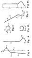
- Figures 1- 3A illustrate a surgical instrument for use on one side of the patient's body.
- Figures 4-6A disclose a surgical instrument for use on the opposite side of the patient's body.
- the surgical instrument 10 includes a straight portion 12, a helical portion 14, and a distal end region 15.
- the surgical instrument 20 includes a straight portion 22, a helical portion 24, and a distal end region 25.
- the surgical instruments 10 and 20 include handles 11 and 21 ( Fig. 8 ) which are not shown in Figures 1-6A .
- the surgical instruments 10 and 20 are adapted for a surgical procedure for reconstruction of the vaginal vault, as described more fully below.
- the cross sectional shape of the straight and helical portions can be of a wide variety of shapes and is preferably small.
- the diameter is preferably less than about 5.5 mm and more than about 0.5 mm.
- the surgical instrument 10 may have a diameter of 0.3175 cm (0.125 inches).
- the length L1' is preferably more than about 12.7 cm (5 inches) and may be about 15.24 cm (6 inches), the length L2' is preferably more than 2.54 cm (1 inch), more preferably more than 5.08 cm (2 inches) and even more preferably about 7.01 cm (2.76 inches).
- the length L1' is preferably less than 30.48 cm (twelve (12) inches).
- the width W' is preferably more than 2.54 cm (one inch) and less than about 22.86 cm (9 inches). In a preferred embodiment the width W' may be about 5.461 cm (2.15 inches). Preferably about 5.08 cm (two inches) of the straight portion 12 project from the end of the handle 11.
- the helical portion 14 preferably has a radius of at least 1.27 cm (0.5 inches), more preferably 2.096 cm (0.825 inches) and a pitch of at least about 5.08 cm (2 inches) preferably about 9.271 cm (3.65 inches).
- the surgical instrument may be formed about a mandrel with a diameter of 3.81 cm (1.5 inches) and a groove (for receiving the surgical instrument) with a pitch of 7.62 cm (3 inches).
- the axis A' of the helical portion 14 is offset from the longitudinal axis of the straight portion 12 (see Figures 1 and 3 ). In this embodiment, the offset is about 8 degrees. In a preferred embodiment, the offset for both instruments 10 and 20 is the same and at least 5 degrees.
- the bend between the straight and helical portions 12 and 14 may have a radius of about 0.762 cm (0.3 inches).
- the distal end portion 15 of the surgical instrument points away from the handle 11 ( Fig. 8 ) and at an acute angle relative to a plane that is perpendicular to the longitudinal axis of the straight portion 12 of the instrument.
- length L1 may be about 15.24 cm (6 inches)
- the length L2 is about 7.01 cm (2.76 inches)
- width W of about 5.461 cm (2.15 inches).
- the axis A of the helical portion 24 is offset from the longitudinal axis of the straight portion 22.
- the helical portion 24 preferably has a radius of 2.096 cm (0.825 inches) and a pitch of about 9.271 cm (3.65 inches).
- the ranges for the size and shape of the instrument 20 are the same as described above for the instrument 10.
- the surgical instruments 10 and 20 may be constructed from any suitable polymeric or metallic material.
- One suitable material is stainless steel 17-4 PH hardened to H900.
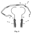
- Figure 8 shows an assembly of surgical articles 10, 20 and 30 for treating prolapse.
- the assembly preferably includes surgical articles 10 and 20 and an implant assembly 30 with dilating connectors 35, implant 34 and separable insertion sheath 32.
- the dilators and insertions sheath are optional.
- the distal end portions of the surgical instruments 10 and 20 may include eyelets for receiving the implant 34.
- the distal end regions 15 and 25 may have surfaces that are specially shaped to engage complementary surfaces on the dilating connectors 35 of an implant assembly 30.
- Such assemblies are disclosed in published U.S. Pat. Application Nos. 2003/0171644-A1 and 2003/0176875-A1 .
- the implant assemblies 30 typically include an implantable material 34 that remains in the body.
- the implantable material may comprise synthetic or non-synthetic materials or hybrids, composites or combinations thereof.
- a synthetic material is preferable.
- Suitably synthetic materials include polymerics, and plastics, and any combination of such materials. Commercial examples of such materials include Mersile TM , Teflon TM , Gore-Tex TM , Silastic TM , Marlex TM , Prolene TM , and Vaskutek TM . Other examples of suitable materials include those disclosed in U.S. Patent No. 6,652,450 . Specific examples of synthetic sling materials include absorbable and non-absorbable materials such as polypropylene, polyethylene, nylon, PLLA and PGA. Additional meshes are disclosed in Dietz et al., Mechanical Properties of Urogynecologic Implant Materials, Int. Urogynecol. J. (2003) 14: 239-243 ; and Iglesia et al., The Use of Mesh in Gynecologic Surgery, Int. Urogynecol. J. (1997) 8:105-115 .
- Possible non-synthetic materials include allografts, homografts, heterografts, autologous tissues, cadaveric fascia and fascia lata.
- Figure 7 shows a prolapsed vagina V and a female pelvis with obturator foramen O.
- Figures 9 through 22 illustrate one example of a surgical procedure for treating prolapse.
- the goal of the procedure is to perform a vaginal vault suspension using an implant fixed relative to the vagina (e.g. on or near the vaginal apex).
- Fig. 8 shows surgical instruments 10 and 20 and implant assembly 30 that are conveniently assembled for purposes of conducting the subsequent surgery.
- the surgical instruments 10 and 20 and implant assembly 30 may optionally be packaged together and opened just prior to the procedure.
- the implant assembly 30 preferably includes an implantable surgical mesh 34, a separable insertion sleeve 32 and a pair of dilating connectors 35.
- the implant 34 For fitting the implant 34, at least two routes are possible: one with an anterior dissection and one with posterior dissection. This procedure can be conducted after previous or concomitant hysterectomy and in cases of uterus preservation.
- specific instruments 10 and 20 are passed through the membrane OM in the region of the obturator foramen O to place the implant 34.
- the implant 34 stabilizes the vaginal vault by fixation on both sides through, e.g, pelvic muscles and membranes.
- the posterior vaginal wall is incised longitudinally from the apex AP down to the perineum incision. (Lowest part incision may be done for posterior myorraphy).
- the rectum is dissected from the vaginal wall, preferably substantially the entire portion.
- the para-rectal space is opened in both sides with dissection deeply to the ischial spines IS.
- the index finger of the surgeon can palpate levator ani and deeper, the ischial spine IS.
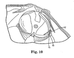
- FIG 9 schematically illustrates a preferred needle passage.
- the needle passage is preferably through the inferior part of the obturator membrane O in the region of the obturator foramen above the ischio-pubic ramus.
- the distal end portion 15 of the instrument 10 is pushed through the obturator membrane O.
- the distal end portion 15 is moved initially toward the region of the patient's ischial spine IS.
- the surgeon's index finger can palpate the needle tip through the muscular wall going to the ischial spine IS.
- the distal end 15 of the instrument is pushing out through the levator ani when it arrives at the level of the spine.
- Fig. 11 shows the surgeon's finger palpating the distal end 15 of the needle.
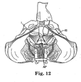
- Figure 12 shows the arrangement after the distal end portion of the needle after it has passed through a vaginal incision I.
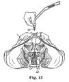
- Fig. 13 the surgeon moves the dilating connector 35 of the implant assembly 30 toward the end portion 15 of the needle.
- the dilating connector 35 is then connected to the needle tip ( Fig. 14 ). This is shown taking place within the vaginal region. Preparation for this step is shown in Fig. 13 .
- the needle 12 is pulled back out obturator O and the implant assembly 30 is essentially in place on one side of the patient.
- Fig. 17 illustrates a scissors S after it has separated the surgical instrument 10 and dilating connector 35 from the remaining portion of the implant assembly 30.
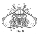
- the implant 34 may be fixed to the vaginal wall with two stitches 101 about 1.5cm from the apex AP. It can also be fixed to the rectum (e.g. in the region or directly to) with two other stitches.
- the implant 34 is between the vagina and rectum. Its passage through the levator ani is on both sides, the fixation point of the vaginal vault suspension.
- Fig. 21 shows the corrected prolapse with the vagina V supported by implant 34.
- the posterior repair can be accomplished with posterior perineo-myorraphy and some times plications of the rectal fascia.
- the vaginal wall may be closed with a suture from the vaginal apex to the lowest region of the perineum.
- the stabilization of the vaginal vault can also be accomplished with an anterior route (e.g. if the surgeon prefers this route for surgical reasons).
- the implant 34 may be implanted by anterior dissection of the anterior vaginal wall.
- the bladder is dissected off the vagina.
- the para-vesical space is opened on both sides going to the ischial spines IS.
- the needles 10 and 20 may be used similarly in the posterior procedure and the implant can be fit through muscular wall in both sides.
- the implant 34 may be fixed to the anterior part of the vaginal vault at the apex AP.
Landscapes
- Health & Medical Sciences (AREA)
- Life Sciences & Earth Sciences (AREA)
- Surgery (AREA)
- Heart & Thoracic Surgery (AREA)
- Engineering & Computer Science (AREA)
- Biomedical Technology (AREA)
- Nuclear Medicine, Radiotherapy & Molecular Imaging (AREA)
- Medical Informatics (AREA)
- Molecular Biology (AREA)
- Animal Behavior & Ethology (AREA)
- General Health & Medical Sciences (AREA)
- Public Health (AREA)
- Veterinary Medicine (AREA)
- Surgical Instruments (AREA)
- Prostheses (AREA)
Claims (13)
- Chirurgisches Instrument (10, 20), das aufweist:einen Griff (11, 21);einen Nadelteil mit einem geradlinigen Abschnitt (12, 22), der vom Griff (11, 21) austritt, und einen im Allgemeinen spiralförmigen Abschnitt (14, 24), der einen distalen Endbereich (15, 25) aufweist, wobei der spiralförmige Abschnitt (14, 24) eine Breite von mehr als etwa 3,81 cm (1,5 Zoll) und weniger als etwa 21,59 cm (8,5 Zoll) sowie einen Radius von mindestens etwa 1,27 cm (0,5 Zoll) aufweist,wobei der Nadelteil so dimensioniert und geformt ist, dass der distale Endbereich (15, 25) zuerst durch das Foramen obturatorium einer Patientin bewegt und in Richtung des Sitzbeinbereichs der Patientin und anschließend in Richtung einer vaginalen Inzision im Bereich des vaginalen Apex geschoben werden kann, so dass am distalen Ende (15, 25) der Nadel ein Implantat aufgenommen und durch die vaginale Inzision hindurch durch das Foramen obturatorium der Patientin bewegt werden kann;dadurch gekennzeichnet, dass die Neigung des spiralförmigen Abschnitts des Griffes mindestens 5,08 cm (2 Zoll) lang ist und dass der geradlinige Abschnitt (12, 22) des Instruments (10, 20) eine Längsachse hat und der spiralförmige Abschnitt (14, 24) eine Achse (A, A') hat, die nicht parallel zur Achse des geradlinigen Abschnitts ist.
- Chirurgisches Instrument nach Anspruch 1, wobei der im Allgemeinen spiralförmige Abschnitt (14, 24) einen linkshändig anwendbaren spiralförmigen Abschnitt aufweist.
- Chirurgisches Instrument nach Anspruch 1, wobei der im Allgemeinen spiralförmige Abschnitt (14, 24) einen rechtshändig anwendbaren spiralförmigen Abschnitt aufweist.
- Chirurgisches Instrument nach Anspruch 1, wobei der Nadelteil einen im Allgemeinen kreisförmigen Querschnitt mit einem Durchmesser von weniger als etwa 5,5 mm und mehr als etwa 0,5 mm aufweist.
- Chirurgisches Instrument nach Anspruch 1, wobei die Länge des spiralförmigen Abschnitts (14, 24) bei Messung entlang der Längsachse des geradlinigen Abschnitts mehr als 5,08 cm (2 Zoll) und weniger als 30,48 cm (12 Zoll) beträgt.
- Chirurgisches Instrument nach Anspruch 1, wobei der spiralförmige Abschnitt (14, 24) eine Breite von etwa 5,461 cm (2,15 Zoll) aufweist.
- Chirurgisches Instrument nach Anspruch 6, wobei der spiralförmige Abschnitt (14, 24) eine Neigung von etwa 7,62 bis etwa 9,271 cm (3 bis etwa 3,65 Zoll) und einen Radius von etwa 2,0955 cm (0,825 Zoll) aufweist.
- Chirurgisches Instrument nach Anspruch 1, wobei die Achse des geradlinigen Abschnitts und die Achse des spiralförmigen Abschnitts (A, A') einen Winkel von etwa 8 Grad bilden.
- Chirurgisches Instrument nach Anspruch 1, wobei der distale Endabschnitt des Instruments vom Griff (11, 21) weg weist und in einem spitzen Winkel relativ zu einer Ebene senkrecht zur Längsachse der geradlinigen Abschnitts (12, 22) des Instruments (10, 20) verläuft.
- Chirurgisches Instrument nach Anspruch 1, das für das Einfügen eines Implantats (34) zur Behandlung eines weiblichen Prolapses angepasst ist.
- Ausrüstungssatz (30) von chirurgischen Instrumenten für die Behandlung eines weiblichen Prolapses, wobei der Ausrüstungssatz aufweist:ein erstes chirurgisches Instrument (10, 20) nach Anspruch 3;ein zweites chirurgisches Instrument (10, 20) nach Anspruch 2;und ein Implantat (34) zur Behandlung des Prolapses.
- Ausrüstungssatz (30) von chirurgischen Instrumenten nach Anspruch 11, die ferner ein Paar Dilatationsverbinder (35) und Einführhüllen (32), die das Implantat (34) umgeben, aufweisen.
- Ausrüstungssatz (30) nach Anspruch 11, angepasst für die Behandlung eines weiblichen Prolapses.
Applications Claiming Priority (2)
| Application Number | Priority Date | Filing Date | Title |
|---|---|---|---|
| US54598704P | 2004-02-19 | 2004-02-19 | |
| PCT/US2005/006039 WO2005079702A1 (en) | 2004-02-19 | 2005-02-22 | Prolapse repair |
Publications (2)
| Publication Number | Publication Date |
|---|---|
| EP1715809A1 EP1715809A1 (de) | 2006-11-02 |
| EP1715809B1 true EP1715809B1 (de) | 2008-05-07 |
Family
ID=34886225
Family Applications (1)
| Application Number | Title | Priority Date | Filing Date |
|---|---|---|---|
| EP05714066A Expired - Lifetime EP1715809B1 (de) | 2004-02-19 | 2005-02-22 | Prolaps-reparatur |
Country Status (6)
| Country | Link |
|---|---|
| EP (1) | EP1715809B1 (de) |
| AT (1) | ATE394077T1 (de) |
| AU (1) | AU2005215814B2 (de) |
| CA (1) | CA2556193C (de) |
| DE (1) | DE602005006528D1 (de) |
| WO (1) | WO2005079702A1 (de) |
Families Citing this family (41)
| Publication number | Priority date | Publication date | Assignee | Title |
|---|---|---|---|---|
| WO2007002071A1 (en) | 2005-06-21 | 2007-01-04 | Ams Research Corporation | Apparatus for securing a urethral sling to pubic bone |
| WO2007002012A1 (en) | 2005-06-21 | 2007-01-04 | Ams Research Corporation | Apparatus for securing a urethral sling to pubic bone |
| CA2615130A1 (en) | 2005-07-26 | 2007-02-08 | Ams Research Corporation | Methods and systems for treatment of prolapse |
| CN101420909B (zh) | 2006-02-16 | 2011-08-03 | Ams研究公司 | 用于治疗盆腔疾病的手术装置和方法 |
| WO2007137226A2 (en) | 2006-05-19 | 2007-11-29 | Ams Research Corporation | Method and articles for treatment of stress urinary incontinence |
| BRPI0712194A2 (pt) | 2006-06-16 | 2012-03-06 | Ams Research Corporation | Implantes pélvico e cirúrgico combinação ferramenta cirúrgica útil para implantar um implante pélvico métodos de tratamento de uma condição pélvica, e de prolapso vaginal, e, método para manipular um implante cirúrgico |
| WO2007149593A2 (en) | 2006-06-22 | 2007-12-27 | Ams Research Corporation | Adjustable tension incontinence sling assemblies |
| WO2008057261A2 (en) | 2006-10-26 | 2008-05-15 | Ams Research Corporation | Surgical articles for treating pelvic conditions |
| US8951185B2 (en) | 2007-10-26 | 2015-02-10 | Ams Research Corporation | Surgical articles and methods for treating pelvic conditions |
| BRPI0817018A2 (pt) | 2007-09-21 | 2015-03-24 | Ams Res Corp | Ferramenta para inserção cirúrgica, combinação de ferramenta com uma extensão de um implante, e, método para implantar um implante em um paciente |
| US8727963B2 (en) | 2008-07-31 | 2014-05-20 | Ams Research Corporation | Methods and implants for treating urinary incontinence |
| US9017243B2 (en) | 2008-08-25 | 2015-04-28 | Ams Research Corporation | Minimally invasive implant and method |
| WO2010027796A1 (en) | 2008-08-25 | 2010-03-11 | Ams Research Corporation | Minimally invasive implant and method |
| KR101719512B1 (ko) | 2008-10-27 | 2017-04-04 | 에이엠에스 리서치 코포레이션 | 신축자재한 요소를 갖는 앵커 시스템 및 외과 수술용 바늘 |
| CA2748894C (en) | 2009-02-10 | 2018-11-13 | Ams Research Corporation | Surgical articles and methods for treating urinary incontinence |
| WO2011082287A1 (en) | 2009-12-30 | 2011-07-07 | Ams Research Corporation | Implant systems with tensioning feedback |
| AU2010339416B2 (en) | 2009-12-30 | 2013-10-17 | Boston Scientific Scimed, Inc. | Implantable sling systems and methods |
| AU2010339575B2 (en) | 2009-12-30 | 2013-04-18 | Boston Scientific Scimed, Inc. | Elongate implant system and method for treating pelvic conditions |
| US9393091B2 (en) | 2009-12-31 | 2016-07-19 | Astora Women's Health, Llc | Suture-less tissue fixation for implantable device |
| US9445881B2 (en) | 2010-02-23 | 2016-09-20 | Boston Scientific Scimed, Inc. | Surgical articles and methods |
| EP3721832B1 (de) | 2010-02-23 | 2023-03-29 | Boston Scientific Scimed, Inc. | Chirurgische artikel für inkontinenzbehandlung |
| DE102010013917A1 (de) * | 2010-04-01 | 2011-10-06 | Karl Storz Gmbh & Co. Kg | Medizinisches Instrument für einen minimalinvasiven Eingriff |
| US10028813B2 (en) | 2010-07-22 | 2018-07-24 | Boston Scientific Scimed, Inc. | Coated pelvic implant device and method |
| US9572648B2 (en) | 2010-12-21 | 2017-02-21 | Justin M. Crank | Implantable slings and anchor systems |
| US9125717B2 (en) | 2011-02-23 | 2015-09-08 | Ams Research Corporation | Implant tension adjustment system and method |
| US8808162B2 (en) | 2011-03-28 | 2014-08-19 | Ams Research Corporation | Implants, tools, and methods for treatment of pelvic conditions |
| US20120253108A1 (en) | 2011-03-28 | 2012-10-04 | Fischer Brian G | Implants, tools, and methods for treatment of pelvic conditions |
| US9492259B2 (en) | 2011-03-30 | 2016-11-15 | Astora Women's Health, Llc | Expandable implant system |
| US10058240B2 (en) | 2011-06-29 | 2018-08-28 | Boston Scientific Scimed, Inc. | Systems, implants, tools, and methods for treatments of pelvic conditions |
| US20130006049A1 (en) | 2011-06-30 | 2013-01-03 | Alexander James A | Implants, tools, and methods for treatments of pelvic conditions |
| US9351723B2 (en) | 2011-06-30 | 2016-05-31 | Astora Women's Health, Llc | Implants, tools, and methods for treatments of pelvic conditions |
| EP2734148B1 (de) | 2011-07-22 | 2019-06-05 | Boston Scientific Scimed, Inc. | Beckenimplantatsystem |
| US9414903B2 (en) | 2011-07-22 | 2016-08-16 | Astora Women's Health, Llc | Pelvic implant system and method |
| US9492191B2 (en) | 2011-08-04 | 2016-11-15 | Astora Women's Health, Llc | Tools and methods for treatment of pelvic conditions |
| US20130035555A1 (en) | 2011-08-05 | 2013-02-07 | Alexander James A | Systems, implants, tools, and methods for treatment of pelvic conditions |
| US10098721B2 (en) | 2011-09-01 | 2018-10-16 | Boston Scientific Scimed, Inc. | Pelvic implant needle system and method |
| USD721175S1 (en) | 2011-09-08 | 2015-01-13 | Ams Research Corporation | Backers for surgical indicators |
| USD736382S1 (en) | 2011-09-08 | 2015-08-11 | Ams Research Corporation | Surgical indicator with backers |
| USD721807S1 (en) | 2011-09-08 | 2015-01-27 | Ams Research Corporation | Surgical indicators |
| US10265152B2 (en) | 2011-10-13 | 2019-04-23 | Boston Scientific Scimed, Inc. | Pelvic implant sizing systems and methods |
| US9192458B2 (en) | 2012-02-09 | 2015-11-24 | Ams Research Corporation | Implants, tools, and methods for treatments of pelvic conditions |
Family Cites Families (7)
| Publication number | Priority date | Publication date | Assignee | Title |
|---|---|---|---|---|
| EP0437481B1 (de) | 1988-10-04 | 1995-03-15 | PETROS Peter Emmanuel | Chirurgisches instrument, prothese |
| FR2785521B1 (fr) | 1998-11-10 | 2001-01-05 | Sofradim Production | Dispositif de suspension pour le traitement de prolapsus et d'incontinences urinaires |
| FR2792824B1 (fr) | 1999-04-27 | 2001-06-22 | Sofradim Production | Dispositif de traitement de prolapsus par suspension vaginale |
| US6802807B2 (en) | 2001-01-23 | 2004-10-12 | American Medical Systems, Inc. | Surgical instrument and method |
| AUPR406501A0 (en) | 2001-03-28 | 2001-04-26 | Kaladelfos, George | Treatment of vault prolapse |
| WO2003075792A1 (en) * | 2002-03-07 | 2003-09-18 | Ams Research Corporation | Transobturator surgical articles and methods |
| EP1542596B1 (de) * | 2002-08-29 | 2010-11-24 | Université de Liège | Vorrichtungen für die chirurgische behandlung der harninkontinenz bei frauen |
-
2005
- 2005-02-22 AT AT05714066T patent/ATE394077T1/de active
- 2005-02-22 EP EP05714066A patent/EP1715809B1/de not_active Expired - Lifetime
- 2005-02-22 WO PCT/US2005/006039 patent/WO2005079702A1/en not_active Ceased
- 2005-02-22 CA CA2556193A patent/CA2556193C/en not_active Expired - Lifetime
- 2005-02-22 DE DE602005006528T patent/DE602005006528D1/de not_active Expired - Lifetime
- 2005-02-22 AU AU2005215814A patent/AU2005215814B2/en not_active Expired
Also Published As
| Publication number | Publication date |
|---|---|
| CA2556193A1 (en) | 2005-09-01 |
| DE602005006528D1 (de) | 2008-06-19 |
| WO2005079702A1 (en) | 2005-09-01 |
| EP1715809A1 (de) | 2006-11-02 |
| ATE394077T1 (de) | 2008-05-15 |
| AU2005215814A1 (en) | 2005-09-01 |
| CA2556193C (en) | 2012-12-04 |
| AU2005215814B2 (en) | 2010-06-24 |
Similar Documents
| Publication | Publication Date | Title |
|---|---|---|
| US10912635B2 (en) | Systems and methods for treating a pelvic disorder | |
| AU2005215814B2 (en) | Prolapse repair | |
| US7070556B2 (en) | Transobturator surgical articles and methods | |
| EP1744701B1 (de) | Vorrichtung zur behandlung des vorfalls eines beckenorgans | |
| AU2008236731B2 (en) | Kit for levator avulsion repair | |
| US9173729B2 (en) | Surgical instrument for treating female urinary stress incontinence | |
| AU2009200022A1 (en) | Transobturator surgical articles and methods | |
| AU2011227537B2 (en) | Surgical instrument and method for the treatment of urinary incontinence | |
| CA2809065C (en) | Centering aid for implantable sling | |
| US10245134B2 (en) | Apparatus and methods for the treatment of urinary incontinence |
Legal Events
| Date | Code | Title | Description |
|---|---|---|---|
| PUAI | Public reference made under article 153(3) epc to a published international application that has entered the european phase |
Free format text: ORIGINAL CODE: 0009012 |
|
| 17P | Request for examination filed |
Effective date: 20060816 |
|
| AK | Designated contracting states |
Kind code of ref document: A1 Designated state(s): AT BE BG CH CY CZ DE DK EE ES FI FR GB GR HU IE IS IT LI LT LU MC NL PL PT RO SE SI SK TR |
|
| 17Q | First examination report despatched |
Effective date: 20070102 |
|
| DAX | Request for extension of the european patent (deleted) | ||
| GRAP | Despatch of communication of intention to grant a patent |
Free format text: ORIGINAL CODE: EPIDOSNIGR1 |
|
| GRAS | Grant fee paid |
Free format text: ORIGINAL CODE: EPIDOSNIGR3 |
|
| GRAA | (expected) grant |
Free format text: ORIGINAL CODE: 0009210 |
|
| AK | Designated contracting states |
Kind code of ref document: B1 Designated state(s): AT BE BG CH CY CZ DE DK EE ES FI FR GB GR HU IE IS IT LI LT LU MC NL PL PT RO SE SI SK TR |
|
| REG | Reference to a national code |
Ref country code: GB Ref legal event code: FG4D |
|
| REG | Reference to a national code |
Ref country code: CH Ref legal event code: EP |
|
| REG | Reference to a national code |
Ref country code: IE Ref legal event code: FG4D Free format text: LANGUAGE OF EP DOCUMENT: FRENCH |
|
| REF | Corresponds to: |
Ref document number: 602005006528 Country of ref document: DE Date of ref document: 20080619 Kind code of ref document: P |
|
| PG25 | Lapsed in a contracting state [announced via postgrant information from national office to epo] |
Ref country code: SI Free format text: LAPSE BECAUSE OF FAILURE TO SUBMIT A TRANSLATION OF THE DESCRIPTION OR TO PAY THE FEE WITHIN THE PRESCRIBED TIME-LIMIT Effective date: 20080507 |
|
| PG25 | Lapsed in a contracting state [announced via postgrant information from national office to epo] |
Ref country code: NL Free format text: LAPSE BECAUSE OF FAILURE TO SUBMIT A TRANSLATION OF THE DESCRIPTION OR TO PAY THE FEE WITHIN THE PRESCRIBED TIME-LIMIT Effective date: 20080507 Ref country code: ES Free format text: LAPSE BECAUSE OF FAILURE TO SUBMIT A TRANSLATION OF THE DESCRIPTION OR TO PAY THE FEE WITHIN THE PRESCRIBED TIME-LIMIT Effective date: 20080818 Ref country code: FI Free format text: LAPSE BECAUSE OF FAILURE TO SUBMIT A TRANSLATION OF THE DESCRIPTION OR TO PAY THE FEE WITHIN THE PRESCRIBED TIME-LIMIT Effective date: 20080507 |
|
| NLV1 | Nl: lapsed or annulled due to failure to fulfill the requirements of art. 29p and 29m of the patents act | ||
| PG25 | Lapsed in a contracting state [announced via postgrant information from national office to epo] |
Ref country code: PL Free format text: LAPSE BECAUSE OF FAILURE TO SUBMIT A TRANSLATION OF THE DESCRIPTION OR TO PAY THE FEE WITHIN THE PRESCRIBED TIME-LIMIT Effective date: 20080507 |
|
| PG25 | Lapsed in a contracting state [announced via postgrant information from national office to epo] |
Ref country code: IS Free format text: LAPSE BECAUSE OF FAILURE TO SUBMIT A TRANSLATION OF THE DESCRIPTION OR TO PAY THE FEE WITHIN THE PRESCRIBED TIME-LIMIT Effective date: 20080907 |
|
| PG25 | Lapsed in a contracting state [announced via postgrant information from national office to epo] |
Ref country code: DK Free format text: LAPSE BECAUSE OF FAILURE TO SUBMIT A TRANSLATION OF THE DESCRIPTION OR TO PAY THE FEE WITHIN THE PRESCRIBED TIME-LIMIT Effective date: 20080507 Ref country code: SE Free format text: LAPSE BECAUSE OF FAILURE TO SUBMIT A TRANSLATION OF THE DESCRIPTION OR TO PAY THE FEE WITHIN THE PRESCRIBED TIME-LIMIT Effective date: 20080807 Ref country code: LT Free format text: LAPSE BECAUSE OF FAILURE TO SUBMIT A TRANSLATION OF THE DESCRIPTION OR TO PAY THE FEE WITHIN THE PRESCRIBED TIME-LIMIT Effective date: 20080507 Ref country code: CZ Free format text: LAPSE BECAUSE OF FAILURE TO SUBMIT A TRANSLATION OF THE DESCRIPTION OR TO PAY THE FEE WITHIN THE PRESCRIBED TIME-LIMIT Effective date: 20080507 |
|
| PG25 | Lapsed in a contracting state [announced via postgrant information from national office to epo] |
Ref country code: RO Free format text: LAPSE BECAUSE OF FAILURE TO SUBMIT A TRANSLATION OF THE DESCRIPTION OR TO PAY THE FEE WITHIN THE PRESCRIBED TIME-LIMIT Effective date: 20080507 Ref country code: BE Free format text: LAPSE BECAUSE OF FAILURE TO SUBMIT A TRANSLATION OF THE DESCRIPTION OR TO PAY THE FEE WITHIN THE PRESCRIBED TIME-LIMIT Effective date: 20080507 Ref country code: PT Free format text: LAPSE BECAUSE OF FAILURE TO SUBMIT A TRANSLATION OF THE DESCRIPTION OR TO PAY THE FEE WITHIN THE PRESCRIBED TIME-LIMIT Effective date: 20081007 Ref country code: SK Free format text: LAPSE BECAUSE OF FAILURE TO SUBMIT A TRANSLATION OF THE DESCRIPTION OR TO PAY THE FEE WITHIN THE PRESCRIBED TIME-LIMIT Effective date: 20080507 |
|
| PLBE | No opposition filed within time limit |
Free format text: ORIGINAL CODE: 0009261 |
|
| STAA | Information on the status of an ep patent application or granted ep patent |
Free format text: STATUS: NO OPPOSITION FILED WITHIN TIME LIMIT |
|
| 26N | No opposition filed |
Effective date: 20090210 |
|
| PG25 | Lapsed in a contracting state [announced via postgrant information from national office to epo] |
Ref country code: EE Free format text: LAPSE BECAUSE OF FAILURE TO SUBMIT A TRANSLATION OF THE DESCRIPTION OR TO PAY THE FEE WITHIN THE PRESCRIBED TIME-LIMIT Effective date: 20080507 Ref country code: BG Free format text: LAPSE BECAUSE OF FAILURE TO SUBMIT A TRANSLATION OF THE DESCRIPTION OR TO PAY THE FEE WITHIN THE PRESCRIBED TIME-LIMIT Effective date: 20080807 |
|
| PGFP | Annual fee paid to national office [announced via postgrant information from national office to epo] |
Ref country code: IE Payment date: 20090305 Year of fee payment: 5 |
|
| PG25 | Lapsed in a contracting state [announced via postgrant information from national office to epo] |
Ref country code: IT Free format text: LAPSE BECAUSE OF FAILURE TO SUBMIT A TRANSLATION OF THE DESCRIPTION OR TO PAY THE FEE WITHIN THE PRESCRIBED TIME-LIMIT Effective date: 20080507 |
|
| PG25 | Lapsed in a contracting state [announced via postgrant information from national office to epo] |
Ref country code: MC Free format text: LAPSE BECAUSE OF NON-PAYMENT OF DUE FEES Effective date: 20090228 |
|
| REG | Reference to a national code |
Ref country code: CH Ref legal event code: PL |
|
| PG25 | Lapsed in a contracting state [announced via postgrant information from national office to epo] |
Ref country code: LI Free format text: LAPSE BECAUSE OF NON-PAYMENT OF DUE FEES Effective date: 20090228 Ref country code: CH Free format text: LAPSE BECAUSE OF NON-PAYMENT OF DUE FEES Effective date: 20090228 |
|
| REG | Reference to a national code |
Ref country code: FR Ref legal event code: ST Effective date: 20091030 |
|
| PG25 | Lapsed in a contracting state [announced via postgrant information from national office to epo] |
Ref country code: FR Free format text: LAPSE BECAUSE OF NON-PAYMENT OF DUE FEES Effective date: 20090302 |
|
| PG25 | Lapsed in a contracting state [announced via postgrant information from national office to epo] |
Ref country code: GR Free format text: LAPSE BECAUSE OF FAILURE TO SUBMIT A TRANSLATION OF THE DESCRIPTION OR TO PAY THE FEE WITHIN THE PRESCRIBED TIME-LIMIT Effective date: 20080808 |
|
| PG25 | Lapsed in a contracting state [announced via postgrant information from national office to epo] |
Ref country code: IE Free format text: LAPSE BECAUSE OF NON-PAYMENT OF DUE FEES Effective date: 20100222 |
|
| PG25 | Lapsed in a contracting state [announced via postgrant information from national office to epo] |
Ref country code: LU Free format text: LAPSE BECAUSE OF NON-PAYMENT OF DUE FEES Effective date: 20090222 |
|
| PG25 | Lapsed in a contracting state [announced via postgrant information from national office to epo] |
Ref country code: HU Free format text: LAPSE BECAUSE OF FAILURE TO SUBMIT A TRANSLATION OF THE DESCRIPTION OR TO PAY THE FEE WITHIN THE PRESCRIBED TIME-LIMIT Effective date: 20081108 |
|
| PG25 | Lapsed in a contracting state [announced via postgrant information from national office to epo] |
Ref country code: TR Free format text: LAPSE BECAUSE OF FAILURE TO SUBMIT A TRANSLATION OF THE DESCRIPTION OR TO PAY THE FEE WITHIN THE PRESCRIBED TIME-LIMIT Effective date: 20080507 |
|
| PG25 | Lapsed in a contracting state [announced via postgrant information from national office to epo] |
Ref country code: CY Free format text: LAPSE BECAUSE OF FAILURE TO SUBMIT A TRANSLATION OF THE DESCRIPTION OR TO PAY THE FEE WITHIN THE PRESCRIBED TIME-LIMIT Effective date: 20080507 |
|
| PGFP | Annual fee paid to national office [announced via postgrant information from national office to epo] |
Ref country code: AT Payment date: 20240126 Year of fee payment: 20 |
|
| PGFP | Annual fee paid to national office [announced via postgrant information from national office to epo] |
Ref country code: DE Payment date: 20240109 Year of fee payment: 20 Ref country code: GB Payment date: 20240111 Year of fee payment: 20 |
|
| REG | Reference to a national code |
Ref country code: DE Ref legal event code: R071 Ref document number: 602005006528 Country of ref document: DE |
|
| REG | Reference to a national code |
Ref country code: GB Ref legal event code: PE20 Expiry date: 20250221 |
|
| REG | Reference to a national code |
Ref country code: AT Ref legal event code: MK07 Ref document number: 394077 Country of ref document: AT Kind code of ref document: T Effective date: 20250222 |
|
| PG25 | Lapsed in a contracting state [announced via postgrant information from national office to epo] |
Ref country code: GB Free format text: LAPSE BECAUSE OF EXPIRATION OF PROTECTION Effective date: 20250221 |