EP1715935B1 - Mikrofiltervorrichtung mit bypass und zugehöriges auslegungsverfahren - Google Patents
Mikrofiltervorrichtung mit bypass und zugehöriges auslegungsverfahren Download PDFInfo
- Publication number
- EP1715935B1 EP1715935B1 EP04712626A EP04712626A EP1715935B1 EP 1715935 B1 EP1715935 B1 EP 1715935B1 EP 04712626 A EP04712626 A EP 04712626A EP 04712626 A EP04712626 A EP 04712626A EP 1715935 B1 EP1715935 B1 EP 1715935B1
- Authority
- EP
- European Patent Office
- Prior art keywords
- oil
- flow
- pressure difference
- maximum
- pressure
- Prior art date
- Legal status (The legal status is an assumption and is not a legal conclusion. Google has not performed a legal analysis and makes no representation as to the accuracy of the status listed.)
- Expired - Lifetime
Links
- 238000000034 method Methods 0.000 title claims abstract description 14
- 238000013461 design Methods 0.000 title claims abstract description 9
- 238000001914 filtration Methods 0.000 claims description 15
- 239000000463 material Substances 0.000 description 9
- 230000000694 effects Effects 0.000 description 5
- 239000002245 particle Substances 0.000 description 4
- 229920003043 Cellulose fiber Polymers 0.000 description 2
- 230000002349 favourable effect Effects 0.000 description 2
- 230000035515 penetration Effects 0.000 description 2
- 230000005540 biological transmission Effects 0.000 description 1
- 230000000903 blocking effect Effects 0.000 description 1
- 238000004140 cleaning Methods 0.000 description 1
- 230000003749 cleanliness Effects 0.000 description 1
- 238000004891 communication Methods 0.000 description 1
- 230000010485 coping Effects 0.000 description 1
- 238000001595 flow curve Methods 0.000 description 1
- 230000001050 lubricating effect Effects 0.000 description 1
- 238000012423 maintenance Methods 0.000 description 1
- 238000000691 measurement method Methods 0.000 description 1
- 230000035939 shock Effects 0.000 description 1
Images

Classifications
-
- B—PERFORMING OPERATIONS; TRANSPORTING
- B01—PHYSICAL OR CHEMICAL PROCESSES OR APPARATUS IN GENERAL
- B01D—SEPARATION
- B01D35/00—Filtering devices having features not specifically covered by groups B01D24/00 - B01D33/00, or for applications not specifically covered by groups B01D24/00 - B01D33/00; Auxiliary devices for filtration; Filter housing constructions
- B01D35/14—Safety devices specially adapted for filtration; Devices for indicating clogging
- B01D35/147—Bypass or safety valves
-
- B—PERFORMING OPERATIONS; TRANSPORTING
- B01—PHYSICAL OR CHEMICAL PROCESSES OR APPARATUS IN GENERAL
- B01D—SEPARATION
- B01D27/00—Cartridge filters of the throw-away type
- B01D27/10—Safety devices, e.g. by-passes
- B01D27/103—Bypass or safety valves
Definitions
- the present invention relates to a micro-filter device as defined in the preamble of claim 4 and to a method for designing the same as defined by claim 1.
- micro-filtering devices are generally known, e.g. from the PCT-patent publication WO-0107142 in the name of Applicant, and from SAE paper 2001-01-0867 "Automatic transmission hydraulic system cleanliness - the effects of operating conditions, measurement techniques and high efficiency filters", which document is hereby regarded included.
- the present micro-filter is cellulose fibre based.
- Such cellulose fibre based micro-filters rely on electrostatic forces for binding particles while on their way through the filter material.
- micro filters rely on a relatively thick body of filtering material through which oil is to be passed, and within which a main part of the "filtering" effect takes place, at least for the smallest particles.
- filtering solely takes place on the surface of the material, for which reason the latter is maximised by using folded or pleated cardboard or other sheet material.
- micro-filter element For coping with this problem with a micro-filter element, the latter would have to be chosen with small resistance to oil penetration, i.e. with relatively low density and/or thickness of the filtering material.
- a maximum allowable pressure difference is created over the filter device, and thus a maximum flow of oil through the micro fitter element, by both the application of a by-pass flow over the filter element via a restriction, and by the use of a valve.
- the restriction is defined by departing from allowed pressure difference at the lowest given oil flow through the system, while the valve system limits the pressure difference at larger flows by opening at the allowable pressure difference at a given largest flow of oil.
- the mentioned by-pass flows may as well be provided in e.g. the housing of the filter device, they are according to the invention preferably provided as part of, or at least directly related to the filter element According to a further preferred embodiment the orifice and valve means are preferably integrated into a single unit. Favourable use is further made of pressure means known per se for pressurising an end closure means to an axial end face of the element, by using the latter for maintaining at least part of the valve system together. In this manner the valve system may at least partially favourably be produced and provided in loose parts.
- Figure one depicts a filtering device 1 comprising a housing 2 showing an upper lid part 3, a bottom lid part 4 and a central body 5 comprising a chamber 6 within which a filter element 7 is situated.
- the device shows communication ports 9 and 10, with port 9 forming an inlet and port 10 forming an outlet port, which ports may be connected to the leads of a hydraulic system, e.g. for lubricating a mechanical device in which the filter device may be incorporated.
- the filter element 7 is in line with the current example preferably cylindrically shaped and comprises filtering material 8, carried by a central, perforated core 12.
- the core 12 in the current example comprises axially oriented, elongated perforations 13, of a length virtually matching that of the filter element 7. Alternative perforations such as bores or square holes may as well be used.
- the core 12 defines an interior space 14 for receiving oil filtered by the element 7 and passed through the perforations 13.
- the interior space 14 communicates with outlet port 10 of the filter device 1.
- closure elements which are of matching flattened shape.
- closure elements in principle come loose, and are pressed against the respective element end face, such like closure element 15 depicted in the example.
- At least one of such elements may however also be integrated in the filter housing, e.g. by the part enclosed by receiving rims 16 in the bottom lid part 3.
- Such closure elements and/or ⁇ parts are preferably provided with annular and concentrically disposed ribs, designed for axial penetration in the filter material 8, thus providing an additional filtering safety for in unexpected cases where e.g. through pressure shocks in a said hydraulic system, the filter might become axially somewhat dislocated.
- the filter element 7 is pressed between the closure elements 15 and 5 via an elastically deformable means 17 such as a spring element, here embodied by a helical pressure spring.
- a spring element here embodied by a helical pressure spring.
- the spring element 17 rests against the upper lid part 3 under presence of a location means such as the depicted dimple 18 or such as a protrusion, which means preferably correspond in diameter with the outer respectively inner diameter of the elastically means 17.
- the latter in a corresponding manner rests against the closure element 15, in casu via a loosely positioned central part 19, which is provided with a central bore 20, received by the main part of the closure element 15 in a positioning and receiving edge 21.
- the parts 19 and 15 may be formed as a whole.
- a pressure valve system 22 located in the interior space 14 of the filter element 7. It is in the present example supported by a rim 23, which in tum is supported by the closure element 15 via minor pillars.
- the valve system 22 further comprises a valve 25, which is supported, alternatively denoted urged towards the closure element, by an elastically deformable element 24, here in conformance with preference embodied by a helical pressure spring.
- the valve 25 is preferably provided with a projection or dimple corresponding to the inner or outer diameter of the pressure spring so as to promote stability of the valve 25.
- a small passage is however provided from chamber 6 to interior space 14 by means of a bore 26, located preferably centrally in the valve 25, which bore provides for a minimum of oil flow by-passing the filter element at all times.
- the bore 26, alternatively denoted orifice 26, ensures a constant pressure drop ( ⁇ difference) over the filter device. In particular it does so independently from temperature.
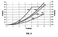
- Figure 2 illustrates a design problem, existing at applying micro-filters in an in-line configuration and underlying the current invention. It further illustrates a design method for designing a filter device in accordance with the example of figure 1 .
- a maximum allowed pressure difference P1 is allowed over a filter device. This maximum difference is set for large flows of oil through the system, and consequently through the filter device. The maximum thus set may however not be favourable for the operation of a micro-filter device.
- This requirement which is often of no problem to full flow filters, can become even more disadvantageous by the fact that often at modest flows, a further, even lower allowed pressure difference P2 is often set.
- P2 is in line with typical automotive values set at 100 mBar at low quantities of oil flow.
- the flow through the filter element 7 be optimised for the given lower amount of flow, i.e. at P2, in that a restriction of smaller diameter would have been provided, the pressure difference Pd over the filter device 1 would in accordance with flow curve Fb2, become double of what is allowed at the given large flow of P2. Therefore, in order to optimise the flow of oil through the micro-filter 7 in relation to the flow of oil through the conceived by pass means for the filter element, it is in accordance with the invention further conceived to include in the by-pass means a pressure valve system 22, which opens at 400 mBar. This provision ensures that the requirement set by P1 will be met al all times, i.e.
- the maximum amount of flow of 1,4 Umin through the micro-filter is in this example already reached at about 8 l/min instead of at about 11,5 l/min, as would have been the case in the situation where the micro filter device would have been adapted to the requirements solely by the use of a restriction.
- the invention thus relates to a method of design for optimising the use of a micro-filter for the situation in which at different flows through the device different pressure differences over the filter device are allowed.
Landscapes
- Chemical & Material Sciences (AREA)
- Chemical Kinetics & Catalysis (AREA)
- Filtration Of Liquid (AREA)
- Lubrication Details And Ventilation Of Internal Combustion Engines (AREA)
- Fluid-Pressure Circuits (AREA)
- Safety Valves (AREA)
- Electrical Discharge Machining, Electrochemical Machining, And Combined Machining (AREA)
- Separation Using Semi-Permeable Membranes (AREA)
Claims (9)
- Verfahren zur Auslegung einer Mikrofiltervorrichtung (1) um selbige zur Verwendung in einer Situation zu optimieren, in der bei unterschiedlichen Ölflüssen durch die Vorrichtung (1) unterschiedliche Druckdifferenzen Pd auf die Vorrichtung (1) erlaubt sind, umfassend die Schritte des Bestimmens des minimalen Betrags, insbesondere des minimalen Querschnitts einer Drosselstelle (26), um zu erlauben, dass eine minimale Menge eines Ölflusses zur Überbrückung eines Mikrofilterelements (7) der Vorrichtung bei allen Bedingungen, die erforderlich ist, um eine vorgegebene Maximaldruckdifferenz (P2) auf die Vorrichtung bei einer niedrigsten vorgegebenen Menge an Ölfluss durch die Vorrichtung (1) zu erlangen, und zur Begrenzung der maximalen Druckdifferenz Pd auf eine maximale Druckdifferenz (P1), die bei einer größten vorgegebenen Menge an Ölfluss durch die Vorrichtung (1) durch die Verwendung eines Druckventilsystems (22) gegeben ist, das sich bei der maximalen Druckdifferenz öffnet und einen zweiten Fluss an Öl schafft, der mittels Bypass an dem Filterelement (7) vorbei fließt, wenn die besagte maximale Druckdifferenz (P1) erreicht wurde.
- Verfahren nach Anspruch 1, wobei der Querschnitt der Drosselstelle (26) so ausgewählt wird, dass er innerhalb eines Bereichs von minus 10 % von und zu einem Querschnitt liegt, der erforderlich ist, um besagte maximal zulässige Druckdifferenz (P2) bei besagtem geringsten vorgegebenen Öldurchfluss durch die Vorrichtung zu erlangen, vorzugsweise gleich der Druckdifferenz (P2).
- Verfahren nach Anspruch 1 oder 2, wobei der Öffnungsdruck des Ventilsystems (22) so ausgelegt wird, dass er ein Druckdifferenzwert Pd ist, welcher bei dem besagten maximalen vorgegebenen Öldurchfluss innerhalb eines Bereiches von minus 10 % von und zu dem vorgegebenen maximalen Druckdifferenzwert (P 1) liegt, vorzugsweise gleich der Druckdifferenz (P1).
- Verfahren nach einem der vorstehenden Ansprüche, wobei der Querschnitt der Drosselblende (26) und/oder der Öffnungsdruck des Druckventilsystems (22) wie er auf eine Ausgestaltung aufgebracht wird, die aus dem Verfahren folgt, auf irgendeinen der angegebenen Werte eingestellt ist, insbesondere auf einen kleinsten zulässigen Querschnitt, der so definiert wurde, und/oder auf den Druckventilöffnungswert bei der maximale zulässigen Druckdifferenz.
- Filtervorrichtung (1) umfassend einen Mikrofilter (7), dessen axiale Endseiten zumindest in weitem Maße zum Durchtritt für Öl durch axiale Endseitenschließmittel (5, 15) geschlossen sind, dadurch gekennzeichnet, dass die Vorrichtung sowohl mit einer Drosselblende (26) und einem Druckventilsystem (22) ausgestattet ist, die erlauben, dass ein Ölfluss mittels Bypass an dem Filterelement (7) vorbeifließt, wobei die Drosselblende (26) einen minimalen Ölfluss bereitstellt, indem Öl mittels Bypass an dem Filterelement (7) bei allen Bedingungen vorbeigeführt wird.
- Vorrichtung (1) nach dem vorstehenden Anspruch, dadurch gekennzeichnet, dass zumindest eine der beiden vorgesehenen Vorrichtungen (26, 22) in ein Verschlussmittel (15) eines Endes aufgenommen ist.
- Vorrichtung (1) nach einem der beiden vorstehenden Ansprüche, dadurch gekennzeichnet, dass das Ventilsystem (22) einen zusätzlichen mittels Bypass vorbeigeleiteten Öldurchfluss bei einer Bedingung bereitstellt, dass eine maximal zulässige Druckdifferenz über die Filtervorrichtung (1) erreicht wird.
- Vorrichtung nach einem der vorstehenden Ansprüche, dadurch gekennzeichnet, dass die Drosselblende (26) in einen Ventilsystemabschnitt integriert ist.
- Vorrichtung nach einem der vorstehenden Ansprüche, dadurch gekennzeichnet, dass das Ventilsystem (22) eine Druckfeder (24) umfasst, die vorzugsweise in den inneren Raum (14) des Filterelements (7) eingebracht ist, vorzugsweise nahe einem von dessen axialen Enden.
Applications Claiming Priority (1)
| Application Number | Priority Date | Filing Date | Title |
|---|---|---|---|
| PCT/IB2004/000419 WO2005087345A1 (en) | 2004-02-19 | 2004-02-19 | Micro-filter device with by pass and method of design therefor |
Publications (3)
| Publication Number | Publication Date |
|---|---|
| EP1715935A1 EP1715935A1 (de) | 2006-11-02 |
| EP1715935B1 true EP1715935B1 (de) | 2008-04-16 |
| EP1715935B9 EP1715935B9 (de) | 2008-11-05 |
Family
ID=34957125
Family Applications (1)
| Application Number | Title | Priority Date | Filing Date |
|---|---|---|---|
| EP04712626A Expired - Lifetime EP1715935B9 (de) | 2004-02-19 | 2004-02-19 | Mikrofiltervorrichtung mit bypass und zugehöriges auslegungsverfahren |
Country Status (7)
| Country | Link |
|---|---|
| US (1) | US20070102331A1 (de) |
| EP (1) | EP1715935B9 (de) |
| JP (1) | JP2007522936A (de) |
| AT (1) | ATE392246T1 (de) |
| DE (1) | DE602004013200T2 (de) |
| ES (1) | ES2306988T3 (de) |
| WO (1) | WO2005087345A1 (de) |
Families Citing this family (1)
| Publication number | Priority date | Publication date | Assignee | Title |
|---|---|---|---|---|
| WO2014172145A1 (en) * | 2013-04-16 | 2014-10-23 | Cummins Filtration Ip, Inc. | Filter element with air vent |
Family Cites Families (8)
| Publication number | Priority date | Publication date | Assignee | Title |
|---|---|---|---|---|
| JPS496264U (de) * | 1972-04-18 | 1974-01-19 | ||
| US3970557A (en) * | 1973-12-26 | 1976-07-20 | Caterpillar Tractor Co. | Impingement baffle equipped oil filter |
| JPH0135218Y2 (de) * | 1986-03-11 | 1989-10-26 | ||
| JPH0425204Y2 (de) * | 1987-06-30 | 1992-06-16 | ||
| JP3468041B2 (ja) * | 1997-08-07 | 2003-11-17 | 三菱電機株式会社 | 浴水浄化ユニット |
| NL1012700C1 (nl) * | 1999-07-26 | 1999-09-16 | Triad Holding Bv | Filterinrichting voor microfiltrering van olie, in het bijzonder voor toepassing bij motoren, alsmede filterhuis bestemd voor een dergelijke filterinrichting. |
| US6875343B2 (en) * | 2001-07-10 | 2005-04-05 | Spx Corporation | Dual direction bypass valve |
| FR2832323A1 (fr) * | 2001-11-19 | 2003-05-23 | Filtrauto | Insert filtrant pour filtre a liquide de moteur a combustion interne, filtre comprenant un tel insert filtrant et vehicule comprenant un tel filtre |
-
2004
- 2004-02-19 JP JP2006553689A patent/JP2007522936A/ja active Pending
- 2004-02-19 US US10/586,553 patent/US20070102331A1/en not_active Abandoned
- 2004-02-19 WO PCT/IB2004/000419 patent/WO2005087345A1/en not_active Ceased
- 2004-02-19 ES ES04712626T patent/ES2306988T3/es not_active Expired - Lifetime
- 2004-02-19 DE DE602004013200T patent/DE602004013200T2/de not_active Expired - Lifetime
- 2004-02-19 EP EP04712626A patent/EP1715935B9/de not_active Expired - Lifetime
- 2004-02-19 AT AT04712626T patent/ATE392246T1/de not_active IP Right Cessation
Also Published As
| Publication number | Publication date |
|---|---|
| JP2007522936A (ja) | 2007-08-16 |
| ATE392246T1 (de) | 2008-05-15 |
| DE602004013200D1 (de) | 2008-05-29 |
| ES2306988T3 (es) | 2008-11-16 |
| WO2005087345A1 (en) | 2005-09-22 |
| EP1715935A1 (de) | 2006-11-02 |
| DE602004013200T2 (de) | 2009-07-09 |
| EP1715935B9 (de) | 2008-11-05 |
| US20070102331A1 (en) | 2007-05-10 |
Similar Documents
| Publication | Publication Date | Title |
|---|---|---|
| US6024869A (en) | Spin-on filter assembly with valve arrangements | |
| EP1658121B1 (de) | Filteranordnung mit entlüftetem filterelement | |
| CN104321522B (zh) | 限定了流入流路和流出流路的过滤元件端板 | |
| EP2108425B1 (de) | Flüssigkeitsfilter mit zwei Filtermedien | |
| US5405527A (en) | Anti-drainback/pressure-relieved filter cartridges for lubricating oil | |
| US8231793B2 (en) | Combination filter arrangement and method | |
| US8146751B2 (en) | Filter element with threaded top endplate | |
| JP5866382B2 (ja) | フィルタ部品 | |
| US20020100720A1 (en) | Filter arrangement for liquids | |
| WO2010135286A1 (en) | Full flow liquid filter with integral bypass filtration | |
| EP0579484B1 (de) | Filter | |
| US6224754B1 (en) | Filter head and liquid filter assembly with valve arrangements | |
| US3690460A (en) | Relief valve for oil filters or the like | |
| US20160074778A1 (en) | Filter Element with Air Vent | |
| US5885447A (en) | Liquid filtration system incorporating a bypass filter element | |
| US7232035B1 (en) | Liquid filter with directional fluid insert | |
| EP1715935B9 (de) | Mikrofiltervorrichtung mit bypass und zugehöriges auslegungsverfahren | |
| WO2005065801A1 (en) | Ultra fine high efficiency filter | |
| EP1838409B1 (de) | Mikrofilterelement | |
| US6974539B1 (en) | Combination filter element support and anti-prefill valve | |
| US20070187308A1 (en) | Pressure relief valve for fluid filter system | |
| EP1440719A1 (de) | Unidirectionaler Austauschfilter und Verfahren dafür | |
| EP4176954B1 (de) | Filterelement mit doppellippendichtung | |
| EP3570955B1 (de) | Filteranordnung | |
| WO1999037908A1 (en) | Spin-on filter assembly with valve arrangements |
Legal Events
| Date | Code | Title | Description |
|---|---|---|---|
| PUAI | Public reference made under article 153(3) epc to a published international application that has entered the european phase |
Free format text: ORIGINAL CODE: 0009012 |
|
| 17P | Request for examination filed |
Effective date: 20060919 |
|
| AK | Designated contracting states |
Kind code of ref document: A1 Designated state(s): AT BE BG CH CY CZ DE DK EE ES FI FR GB GR HU IE IT LI LU MC NL PT RO SE SI SK TR |
|
| 17Q | First examination report despatched |
Effective date: 20061207 |
|
| DAX | Request for extension of the european patent (deleted) | ||
| GRAC | Information related to communication of intention to grant a patent modified |
Free format text: ORIGINAL CODE: EPIDOSCIGR1 |
|
| GRAP | Despatch of communication of intention to grant a patent |
Free format text: ORIGINAL CODE: EPIDOSNIGR1 |
|
| GRAS | Grant fee paid |
Free format text: ORIGINAL CODE: EPIDOSNIGR3 |
|
| GRAA | (expected) grant |
Free format text: ORIGINAL CODE: 0009210 |
|
| AK | Designated contracting states |
Kind code of ref document: B1 Designated state(s): AT BE BG CH CY CZ DE DK EE ES FI FR GB GR HU IE IT LI LU MC NL PT RO SE SI SK TR |
|
| REG | Reference to a national code |
Ref country code: CH Ref legal event code: EP |
|
| REG | Reference to a national code |
Ref country code: IE Ref legal event code: FG4D |
|
| REF | Corresponds to: |
Ref document number: 602004013200 Country of ref document: DE Date of ref document: 20080529 Kind code of ref document: P |
|
| PG25 | Lapsed in a contracting state [announced via postgrant information from national office to epo] |
Ref country code: SI Free format text: LAPSE BECAUSE OF FAILURE TO SUBMIT A TRANSLATION OF THE DESCRIPTION OR TO PAY THE FEE WITHIN THE PRESCRIBED TIME-LIMIT Effective date: 20080416 |
|
| PG25 | Lapsed in a contracting state [announced via postgrant information from national office to epo] |
Ref country code: PT Free format text: LAPSE BECAUSE OF FAILURE TO SUBMIT A TRANSLATION OF THE DESCRIPTION OR TO PAY THE FEE WITHIN THE PRESCRIBED TIME-LIMIT Effective date: 20080916 Ref country code: FI Free format text: LAPSE BECAUSE OF FAILURE TO SUBMIT A TRANSLATION OF THE DESCRIPTION OR TO PAY THE FEE WITHIN THE PRESCRIBED TIME-LIMIT Effective date: 20080416 Ref country code: BG Free format text: LAPSE BECAUSE OF FAILURE TO SUBMIT A TRANSLATION OF THE DESCRIPTION OR TO PAY THE FEE WITHIN THE PRESCRIBED TIME-LIMIT Effective date: 20080716 |
|
| REG | Reference to a national code |
Ref country code: ES Ref legal event code: FG2A Ref document number: 2306988 Country of ref document: ES Kind code of ref document: T3 |
|
| PG25 | Lapsed in a contracting state [announced via postgrant information from national office to epo] |
Ref country code: AT Free format text: LAPSE BECAUSE OF FAILURE TO SUBMIT A TRANSLATION OF THE DESCRIPTION OR TO PAY THE FEE WITHIN THE PRESCRIBED TIME-LIMIT Effective date: 20080416 |
|
| PG25 | Lapsed in a contracting state [announced via postgrant information from national office to epo] |
Ref country code: SE Free format text: LAPSE BECAUSE OF FAILURE TO SUBMIT A TRANSLATION OF THE DESCRIPTION OR TO PAY THE FEE WITHIN THE PRESCRIBED TIME-LIMIT Effective date: 20080716 Ref country code: CZ Free format text: LAPSE BECAUSE OF FAILURE TO SUBMIT A TRANSLATION OF THE DESCRIPTION OR TO PAY THE FEE WITHIN THE PRESCRIBED TIME-LIMIT Effective date: 20080416 Ref country code: DK Free format text: LAPSE BECAUSE OF FAILURE TO SUBMIT A TRANSLATION OF THE DESCRIPTION OR TO PAY THE FEE WITHIN THE PRESCRIBED TIME-LIMIT Effective date: 20080416 |
|
| ET | Fr: translation filed | ||
| PLBE | No opposition filed within time limit |
Free format text: ORIGINAL CODE: 0009261 |
|
| STAA | Information on the status of an ep patent application or granted ep patent |
Free format text: STATUS: NO OPPOSITION FILED WITHIN TIME LIMIT |
|
| PG25 | Lapsed in a contracting state [announced via postgrant information from national office to epo] |
Ref country code: SK Free format text: LAPSE BECAUSE OF FAILURE TO SUBMIT A TRANSLATION OF THE DESCRIPTION OR TO PAY THE FEE WITHIN THE PRESCRIBED TIME-LIMIT Effective date: 20080416 Ref country code: RO Free format text: LAPSE BECAUSE OF FAILURE TO SUBMIT A TRANSLATION OF THE DESCRIPTION OR TO PAY THE FEE WITHIN THE PRESCRIBED TIME-LIMIT Effective date: 20080416 |
|
| 26N | No opposition filed |
Effective date: 20090119 |
|
| PG25 | Lapsed in a contracting state [announced via postgrant information from national office to epo] |
Ref country code: EE Free format text: LAPSE BECAUSE OF FAILURE TO SUBMIT A TRANSLATION OF THE DESCRIPTION OR TO PAY THE FEE WITHIN THE PRESCRIBED TIME-LIMIT Effective date: 20080416 |
|
| PG25 | Lapsed in a contracting state [announced via postgrant information from national office to epo] |
Ref country code: CY Free format text: LAPSE BECAUSE OF FAILURE TO SUBMIT A TRANSLATION OF THE DESCRIPTION OR TO PAY THE FEE WITHIN THE PRESCRIBED TIME-LIMIT Effective date: 20080416 Ref country code: MC Free format text: LAPSE BECAUSE OF NON-PAYMENT OF DUE FEES Effective date: 20090228 |
|
| REG | Reference to a national code |
Ref country code: CH Ref legal event code: PL |
|
| PG25 | Lapsed in a contracting state [announced via postgrant information from national office to epo] |
Ref country code: LI Free format text: LAPSE BECAUSE OF NON-PAYMENT OF DUE FEES Effective date: 20090228 Ref country code: CH Free format text: LAPSE BECAUSE OF NON-PAYMENT OF DUE FEES Effective date: 20090228 |
|
| REG | Reference to a national code |
Ref country code: IE Ref legal event code: MM4A |
|
| PG25 | Lapsed in a contracting state [announced via postgrant information from national office to epo] |
Ref country code: IE Free format text: LAPSE BECAUSE OF NON-PAYMENT OF DUE FEES Effective date: 20090219 |
|
| PG25 | Lapsed in a contracting state [announced via postgrant information from national office to epo] |
Ref country code: GR Free format text: LAPSE BECAUSE OF FAILURE TO SUBMIT A TRANSLATION OF THE DESCRIPTION OR TO PAY THE FEE WITHIN THE PRESCRIBED TIME-LIMIT Effective date: 20080717 |
|
| PG25 | Lapsed in a contracting state [announced via postgrant information from national office to epo] |
Ref country code: LU Free format text: LAPSE BECAUSE OF NON-PAYMENT OF DUE FEES Effective date: 20090219 |
|
| PG25 | Lapsed in a contracting state [announced via postgrant information from national office to epo] |
Ref country code: HU Free format text: LAPSE BECAUSE OF FAILURE TO SUBMIT A TRANSLATION OF THE DESCRIPTION OR TO PAY THE FEE WITHIN THE PRESCRIBED TIME-LIMIT Effective date: 20081017 |
|
| PGFP | Annual fee paid to national office [announced via postgrant information from national office to epo] |
Ref country code: NL Payment date: 20140122 Year of fee payment: 11 |
|
| PGFP | Annual fee paid to national office [announced via postgrant information from national office to epo] |
Ref country code: FR Payment date: 20140224 Year of fee payment: 11 Ref country code: ES Payment date: 20140321 Year of fee payment: 11 Ref country code: TR Payment date: 20140206 Year of fee payment: 11 Ref country code: IT Payment date: 20140220 Year of fee payment: 11 |
|
| PGFP | Annual fee paid to national office [announced via postgrant information from national office to epo] |
Ref country code: GB Payment date: 20140228 Year of fee payment: 11 |
|
| PGFP | Annual fee paid to national office [announced via postgrant information from national office to epo] |
Ref country code: BE Payment date: 20140327 Year of fee payment: 11 |
|
| PGFP | Annual fee paid to national office [announced via postgrant information from national office to epo] |
Ref country code: DE Payment date: 20140430 Year of fee payment: 11 |
|
| PG25 | Lapsed in a contracting state [announced via postgrant information from national office to epo] |
Ref country code: BE Free format text: LAPSE BECAUSE OF NON-PAYMENT OF DUE FEES Effective date: 20150228 |
|
| REG | Reference to a national code |
Ref country code: DE Ref legal event code: R119 Ref document number: 602004013200 Country of ref document: DE |
|
| REG | Reference to a national code |
Ref country code: NL Ref legal event code: V1 Effective date: 20150901 |
|
| PG25 | Lapsed in a contracting state [announced via postgrant information from national office to epo] |
Ref country code: NL Free format text: LAPSE BECAUSE OF NON-PAYMENT OF DUE FEES Effective date: 20150901 |
|
| GBPC | Gb: european patent ceased through non-payment of renewal fee |
Effective date: 20150219 |
|
| REG | Reference to a national code |
Ref country code: FR Ref legal event code: ST Effective date: 20151030 |
|
| PG25 | Lapsed in a contracting state [announced via postgrant information from national office to epo] |
Ref country code: IT Free format text: LAPSE BECAUSE OF NON-PAYMENT OF DUE FEES Effective date: 20150219 |
|
| PG25 | Lapsed in a contracting state [announced via postgrant information from national office to epo] |
Ref country code: DE Free format text: LAPSE BECAUSE OF NON-PAYMENT OF DUE FEES Effective date: 20150901 Ref country code: GB Free format text: LAPSE BECAUSE OF NON-PAYMENT OF DUE FEES Effective date: 20150219 |
|
| PG25 | Lapsed in a contracting state [announced via postgrant information from national office to epo] |
Ref country code: FR Free format text: LAPSE BECAUSE OF NON-PAYMENT OF DUE FEES Effective date: 20150302 |
|
| REG | Reference to a national code |
Ref country code: ES Ref legal event code: FD2A Effective date: 20160930 |
|
| PG25 | Lapsed in a contracting state [announced via postgrant information from national office to epo] |
Ref country code: ES Free format text: LAPSE BECAUSE OF NON-PAYMENT OF DUE FEES Effective date: 20150220 |
|
| PG25 | Lapsed in a contracting state [announced via postgrant information from national office to epo] |
Ref country code: TR Free format text: LAPSE BECAUSE OF NON-PAYMENT OF DUE FEES Effective date: 20150219 |