EP1716018B1 - Systeme camera destine notamment a un systeme de detection d'environnement d'un vehicule - Google Patents
Systeme camera destine notamment a un systeme de detection d'environnement d'un vehicule Download PDFInfo
- Publication number
- EP1716018B1 EP1716018B1 EP05715225A EP05715225A EP1716018B1 EP 1716018 B1 EP1716018 B1 EP 1716018B1 EP 05715225 A EP05715225 A EP 05715225A EP 05715225 A EP05715225 A EP 05715225A EP 1716018 B1 EP1716018 B1 EP 1716018B1
- Authority
- EP
- European Patent Office
- Prior art keywords
- optics
- holding frame
- camera system
- bearing surface
- optics support
- Prior art date
- Legal status (The legal status is an assumption and is not a legal conclusion. Google has not performed a legal analysis and makes no representation as to the accuracy of the status listed.)
- Expired - Lifetime
Links
Images

Classifications
-
- B—PERFORMING OPERATIONS; TRANSPORTING
- B60—VEHICLES IN GENERAL
- B60R—VEHICLES, VEHICLE FITTINGS, OR VEHICLE PARTS, NOT OTHERWISE PROVIDED FOR
- B60R11/00—Arrangements for holding or mounting articles, not otherwise provided for
- B60R11/04—Mounting of cameras operative during drive; Arrangement of controls thereof relative to the vehicle
-
- H—ELECTRICITY
- H04—ELECTRIC COMMUNICATION TECHNIQUE
- H04N—PICTORIAL COMMUNICATION, e.g. TELEVISION
- H04N23/00—Cameras or camera modules comprising electronic image sensors; Control thereof
- H04N23/50—Constructional details
- H04N23/55—Optical parts specially adapted for electronic image sensors; Mounting thereof
-
- H—ELECTRICITY
- H04—ELECTRIC COMMUNICATION TECHNIQUE
- H04N—PICTORIAL COMMUNICATION, e.g. TELEVISION
- H04N23/00—Cameras or camera modules comprising electronic image sensors; Control thereof
- H04N23/57—Mechanical or electrical details of cameras or camera modules specially adapted for being embedded in other devices
Definitions
- the invention relates to a camera system, in particular for an environment detection system of a vehicle, having a holding frame for holding an optics carrier, the optics of which serves to guide incident light onto an image recorder.
- the invention also relates to a holding frame for such a camera system and a method for adjusting the optics carrier having the optics with respect to the image sensor.
- Camera systems for vehicle surroundings detection systems are known from the prior art. Such environment detection systems detect the vehicle environment and provide information for other vehicle systems or for the driver. For example, environment detection systems are known with which the rear area of the vehicle is detected by means of a camera. Other systems provide information during night driving (Night Vision). In addition, systems are known that include cameras that monitor whether the driver is inside the lane (Line Detection Warning Systems).
- the known camera systems each comprise a slide with an optic, in particular with one or more lenses.
- an image sensor is provided, for example an imager chip or image sensor chip.
- the object of the present invention is to provide a camera system in which the optics can be adjusted in a simple manner relative to the image recorder and then permanently fixed. As few individual parts as possible should be used and the camera system should be simple and space-saving.
- the optical carrier By providing the bearing surface parallel to the image recorder, the optical carrier can be displaced in only two spatial directions. A not parallel to the image sensor arrangement of the optics can not be done so. Due to the displaceability of the optics carrier on the support surface of the holding frame, the optics carrier can be moved in a simple manner, manually or automatically, so long in the correct position until the desired position is reached. Upon reaching the desired position position of the optics carrier can be permanently fixed to the support frame.
- a preferred embodiment of the invention provides that the holding frame or the optics carrier comprises biasing means which are adapted to press the optics carrier against the support surface.
- biasing means, the optical carrier or support frame at least partially converts and / or can have behind the advantage that the optics carrier can not be moved in the third spatial direction, ie perpendicular to the plane of the image sensor, without further notice. This ensures that when moving the optics carrier this is moved only in the plane of the support surface.
- By pressing the optical carrier against the support surface is also achieved that the optics carrier is not automatically, for example due to its own weight, moves relative to the support frame.
- the biasing means may be formed as the support surface or contact surface cross, at least perpendicular to the support surface elastically yielding webs, which engage behind the optical carrier or support frame in the adjustment and / or desired position.
- Such elastically yielding webs may for example be integrally connected to the support frame and / or optics carrier, or be integrally formed on the support frame and / or optics carrier. Due to the elastic compliance of the optics carrier can be pressed against the support frame.
- the holding frame is formed such that the optics carrier is inextricably connected in the desired position with the holding frame.
- An undetachable connection can be made, for example, by gluing or welding the optics carrier to the holding frame.
- the holding frame or optics carrier is made of a first plastic and if the optics carrier or holding frame is at least partially made of a second, so light transparent plastic that the support surface is welded to the contact surface of the holding frame for permanent connection.
- a welding takes place especially in the laser welding process. Due to the light-transparent plastic is thereby ensured that the two materials melt on their abutting surfaces. The laser beams can penetrate the corresponding light transparent plastic, without damaging it. A welding can take place in particular in the corner regions of the optics carrier.
- a further, preferred embodiment of the invention provides that the support surface or contact surface is bounded on at least two sides at least in sections by limiting webs.
- the contact surface of the optics carrier on a side on which no boundary web is provided can be pushed onto the support surface.
- biasing means are arranged on the boundary webs.
- the biasing means may be formed integrally with the boundary webs in this context, or they may be formed on the boundary webs.
- the support surface has larger dimensions than the position surface of the object carrier coming to rest on the support surface.
- the image sensor and / or the holding frame can be arranged directly on a printed circuit board in a compact design of the camera system.
- the image sensor can be soldered to printed conductors of the printed circuit board.
- the holding frame can be inserted for example in retaining recesses or screwed by screws to the circuit board.
- a suitable test pattern is projected onto the optics for determining the desired position, and that shifting after step a) takes place until the position of the test pattern corresponds to the image taken by the image recorder of the desired position position.
- the permanent fixing after reaching the adjustment position by Welding and / or bonding of the optics carrier achieved with the support frame.
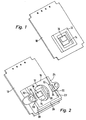
- Camera system shown in detail comprises a printed circuit board 10, on which a Jardinauerauerhalterung 12 including image sensor 14 is arranged.
- the image sensor 14 has a photosensitive surface 16.
- a holding frame 18 is mounted above the Jardinaufrichhalter 12 together with Syndromeaufterrorism 14.
- the holding frame 18 has a central opening 20 through which incident light can reach the photosensitive surface 16.
- the holding frame 18 may be arranged for example by latching or by means of screws on the printed circuit board 10.
- the holding frame 18 has a rectangular bearing surface 22, which runs parallel to the plane of the image recorder 14 or parallel to the printed circuit board 10.
- the support surface 22 is delimited on at least three sides by limiting webs 24, 26, 28.
- each biasing means 30 are provided in the central region.
- the biasing means 30 comprise webs 34 which engage over the support surface 22 in the direction of the central opening 20.
- the webs 34 are also conditionally formed elastically in the direction perpendicular to the support surface 22 direction.
- the biasing means 30 provide longitudinal slots 32.
- the webs 34 are spaced from the support surface 22 by the amount x.
- a lens carrier 36 which has on its side facing away from the holding frame 18 an optics 40 with lenses.
- the optic 40 is arranged at the free end of a sleeve-like portion of the optics carrier 38.
- the optical carrier has on its side facing the holding frame on a support portion 41 with a contact surface 42 which rests on the support surface 22 of the support frame 18.
- the dimensions of the holding surface 42 are smaller than the dimensions of the support surface 22. This ensures that the contact surface 42 of the optics carrier is displaceable on the support surface 22 of the support frame.
- the optical carrier 38 can be pushed under the webs 34 of the biasing means 30 on the side of the support surface 22, on which the limiting webs 24, 26 and 28 are not provided.
- the thickness of the contact portion 41 is chosen so that it is slightly larger than the distance x between the support surface 22 and the webs 34. This ensures that the webs 34 press the contact surface 42 against the support surface 22. A sure concern of the Contact surface 42 on the support surface 22 is ensured.
- the Indian FIG. 4 clearly shows that the web 34 comprises a facing in the direction of the support surface 22 nose 44 which serves to rest against the abutment portion 41 of the optics carrier 38.
- a suitable test image can advantageously be projected onto the optical system 40. If the position of the image picked up by the image recorder does not correspond to the desired position position, then the optics carrier 38 on the support surface 22 can be correspondingly displaced until the desired position position is reached.
- the optical carrier 38 Upon reaching the desired position position of the optical carrier 38 is permanently connected to the support frame 18. This can be done in particular by laser welding.
- the optical carrier 38 is made of a correspondingly transparent material, the laser beams passes through unscathed. The laser beams then strike in the region of the abutment portion on the support surface lying below the abutment portion 41. There, the material of the holding frame is melted; a welding of the optical carrier 38 and the holding frame 18 is effected thereby.
- the welding can advantageously be a spot or line welding in the region of the corners of the contact section 41 or the support surface 22.
- FIG. 3 An exemplary weld is in FIG. 3 indicated by the reference numeral 46.
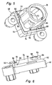
- FIGS. 5 and 6 show a second embodiment of the invention with a holding frame 48 having a central opening 50.
- An intended bearing surface 52 is bounded by two mutually perpendicular limiting webs 54, 56.
- a biasing means 60 is arranged in each case.
- the biasing means 60 comprise, according to FIG. 4 , Webs 64, which have directed towards the support surface 52 tabs 66.
- Optics carrier 70 shown corresponding to the optical carrier 38 has a circumferential, in plan view rectangular abutment portion 72, the support surface 52 side facing a contact surface 74 forms.
- the thickness of the contact portion 72 is slightly larger than the distance of the tabs 66 to the support surface 52. In this way, an arrangement of the optical carrier 70 is achieved on the support frame 48 under a bias voltage.
- the optics carrier 70 can be moved in the plane of the support surface 52.
- the optical carrier 70 is advantageously permanently connected in the region of the abutment portion 72 with the support frame 48, in particular by how to FIG. 3 described, laser welding.
Landscapes
- Engineering & Computer Science (AREA)
- Multimedia (AREA)
- Signal Processing (AREA)
- Mechanical Engineering (AREA)
- Studio Devices (AREA)
- Lens Barrels (AREA)
- Camera Bodies And Camera Details Or Accessories (AREA)
- Transforming Light Signals Into Electric Signals (AREA)
- Control Of Driving Devices And Active Controlling Of Vehicle (AREA)
Claims (14)
- Système de caméra, notamment pour un système d'acquisition de l'environnement d'un véhicule, comprenant un cadre de maintien (18, 48) pour maintenir un porte-optique (38, 70) dont l'optique (40) sert au guidage de la lumière incidente sur un capteur d'image (14), le cadre de maintien (18, 48) présentant une surface d'appui (22, 52) pour une surface d'appui (42, 72) du porte-optique qui est au moins pour l'essentiel disposée parallèlement au plan du capteur d'image (14), caractérisé en ce que le porte-optique peut être coulissé dans une position d'ajustage dans le plan de la surface d'appui (22, 52) jusqu'à atteindre une position voulue de l'optique par rapport au capteur d'image et que le porte-optique peut être fixé à demeure dans la position voulue.
- Système de caméra selon la revendication 1, caractérisé en ce que le cadre de maintien (18, 48) ou le porte-optique (38, 70) comprend des moyens de précontrainte (30, 60) qui sont conçus pour pousser le porte-optique (38, 70) contre la surface d'appui (22, 52).
- Système de caméra selon la revendication 2, caractérisé en ce que les moyens de précontrainte (30, 60) comprennent des brides (34, 64) flexibles par effet élastique qui recouvrent la surface d'appui (22, 52) ou la surface d'appui (42, 72), au moins perpendiculairement à la surface d'appui (22, 52) ou à la surface d'appui (42, 72), lesquelles sont conçues pour venir en prise par l'arrière avec des sections (41, 72) du porte-optique (38, 70) ou du cadre de maintien (18, 48).
- Système de caméra selon la revendication 2 ou 3, caractérisé en ce que les moyens de précontrainte (30, 60) présentent des creux (32, 68) pour réaliser la flexibilité élastique.
- Système de caméra selon la revendication 1, 2 ou 3, caractérisé en ce que le cadre de maintien (18, 48) est configuré de telle sorte que le porte-optique (38, 68), dans la position voulue, peut être relié de manière inamovible avec le cadre de maintien (18, 48).
- Système de caméra selon l'une des revendications précédentes, caractérisé en ce que le cadre de maintien (18, 48) ou le porte-optique (38, 68) est constitué d'une première matière plastique et que le porte-optique (38, 68) ou le cadre de maintien (18, 48), au moins dans certaines sections, est constitué d'une deuxième matière plastique transparente à la lumière de sorte que la surface d'appui (22, 52) peut être soudée avec la surface d'appui (42, 74) du cadre de maintien (18, 48) pour réaliser la liaison inamovible.
- Système de caméra selon l'une des revendications précédentes, caractérisé en ce que la surface d'appui (22, 52) ou la surface d'appui (42, 74) est délimitée au moins par sections par des nervures de délimitation (22, 24, 26, 54, 56) sur au moins deux côtés.
- Système de caméra selon la revendication 7, caractérisé en ce que la surface d'appui (42, 74) du porte-optique (38, 68) peut être insérée sur la surface d'appui (22, 52) par un côté sur lequel n'est prévue aucune nervure de délimitation.
- Système de caméra selon l'une des revendications 2 à 8, caractérisé en ce que les moyens de précontrainte (30, 60) sont disposés sur au moins deux nervures de délimitation (24, 28, 54, 56).
- Système de caméra selon l'une des revendications précédentes, caractérisé en ce que la surface d'appui (22, 52) présente des dimensions plus grandes que la surface d'appui (42, 74) du porte-optique (38, 70) qui vient reposer sur la surface d'appui (22, 52).
- Système de caméra selon l'une des revendications précédentes, caractérisé en ce que le capteur d'image (14) et/ou le cadre de maintien (18, 58) est disposé sur un circuit imprimé (10).
- Procédé pour ajuster un porte-optique (38, 70) qui présente une optique (40) par rapport à un capteur d'image (12), un cadre de maintien (18, 58) présentant une surface d'appui (22, 52) qui est au moins pour l'essentiel disposée parallèlement au plan du capteur d'image (12) et le porte-optique (38, 70) présentant une surface d'appui (42, 74) destinée à être appliquée contre la surface d'appui (22, 52), caractérisé par les étapes suivantes :a) Coulissement de la surface d'appui (42, 74) du porte-optique sur la surface d'appui (22, 52) du cadre de maintien (18, 58) jusqu'à atteindre une position voulue de l'optique (40) par rapport au capteur d'image (12) etb) Fixation à demeure du porte-optique (38, 70) sur le cadre de maintien (18, 58).
- Procédé selon la revendication 12, caractérisé en ce que pour déterminer la position voulue, une image de test appropriée est projetée sur l'optique (40) et que le coulissement selon l'étape a) est effectué jusqu'à ce que la position de l'image de test corresponde à l'image de la position voulue enregistrée par le capteur d'image (12).
- Procédé selon la revendication 12 ou 13, caractérisé en ce que la fixation à demeure est réalisée par soudage et/ou collage.
Applications Claiming Priority (2)
| Application Number | Priority Date | Filing Date | Title |
|---|---|---|---|
| DE102004009920A DE102004009920A1 (de) | 2004-02-20 | 2004-02-20 | Kamerasystem, insbesondere für ein Umfelderfassungssystem eines Fahrzeugs |
| PCT/EP2005/000894 WO2005090127A1 (fr) | 2004-02-20 | 2005-01-29 | Systeme camera destine notamment a un systeme de detection d'environnement d'un vehicule |
Publications (2)
| Publication Number | Publication Date |
|---|---|
| EP1716018A1 EP1716018A1 (fr) | 2006-11-02 |
| EP1716018B1 true EP1716018B1 (fr) | 2010-05-12 |
Family
ID=34853863
Family Applications (1)
| Application Number | Title | Priority Date | Filing Date |
|---|---|---|---|
| EP05715225A Expired - Lifetime EP1716018B1 (fr) | 2004-02-20 | 2005-01-29 | Systeme camera destine notamment a un systeme de detection d'environnement d'un vehicule |
Country Status (7)
| Country | Link |
|---|---|
| US (1) | US20070188893A1 (fr) |
| EP (1) | EP1716018B1 (fr) |
| JP (1) | JP4620066B2 (fr) |
| AT (1) | ATE467531T1 (fr) |
| DE (2) | DE102004009920A1 (fr) |
| ES (1) | ES2343734T3 (fr) |
| WO (1) | WO2005090127A1 (fr) |
Cited By (3)
| Publication number | Priority date | Publication date | Assignee | Title |
|---|---|---|---|---|
| DE102015213575A1 (de) | 2015-02-10 | 2016-08-11 | Robert Bosch Gmbh | Bildaufnahmesystem und ein Kraftfahrzeug |
| DE102015202312A1 (de) | 2015-02-10 | 2016-08-11 | Robert Bosch Gmbh | Bildaufnahmesystem für ein Kraftfahrzeug, Verfahren zur Herstellung eines Bildaufnahmesystems und Spritzgießwerkzeug |
| DE102015205441A1 (de) | 2015-03-25 | 2016-09-29 | Robert Bosch Gmbh | Gehäuse für ein Kamerasystem eines Umfelderfassungssystems eines Kraftfahrzeuges und Verfahren zum Herstellen des Gehäuses für das Kamerasystem des Umfelderfassungssystems des Kraftfahrzeuges |
Families Citing this family (8)
| Publication number | Priority date | Publication date | Assignee | Title |
|---|---|---|---|---|
| DE102006039654A1 (de) * | 2006-08-24 | 2008-03-13 | Valeo Schalter Und Sensoren Gmbh | Kamerasystem, inbesondere für ein Umfelderfassungssystem eines Fahrzeugs, und Montageverfahren |
| JP5198295B2 (ja) * | 2008-01-15 | 2013-05-15 | 富士フイルム株式会社 | 撮像素子の位置調整方法、カメラモジュール製造方法及び装置、カメラモジュール |
| JP5446638B2 (ja) * | 2009-09-11 | 2014-03-19 | 株式会社リコー | レンズ鏡胴および撮像装置 |
| JP5601000B2 (ja) * | 2010-03-31 | 2014-10-08 | 株式会社リコー | 撮像装置 |
| DE102014211720A1 (de) | 2014-06-18 | 2015-12-24 | Robert Bosch Gmbh | Optikträger, Verfahren zur Herstellung eines Optikträgers, Vorrichtung zur Herstellung eines Optikträgers und Kamerasystem |
| EP3378704B1 (fr) * | 2017-03-20 | 2019-10-16 | Veoneer Sweden AB | Système d'imagerie pour véhicule à moteur |
| DE102018202205A1 (de) * | 2018-02-13 | 2019-08-14 | Conti Temic Microelectronic Gmbh | Telekamera für ein Fahrzeug sowie Befestigung einer Telekamera am Fahrzeug |
| CN112524431B (zh) * | 2020-12-29 | 2022-09-06 | 北京中环城境科技有限公司 | 一种环境监测系统 |
Family Cites Families (14)
| Publication number | Priority date | Publication date | Assignee | Title |
|---|---|---|---|---|
| JPS60212070A (ja) * | 1984-04-05 | 1985-10-24 | Sony Corp | 固体撮像装置及び固体撮像装置の生産方法 |
| JPS63314978A (ja) * | 1987-06-18 | 1988-12-22 | Sanyo Electric Co Ltd | 固体撮像カメラ |
| US5642238A (en) * | 1995-01-30 | 1997-06-24 | Mbs Foundry Inc. | Ergonomically efficient side and rear vision system for motor vehicles |
| CA2209993A1 (fr) * | 1995-11-10 | 1997-05-15 | Techno Media Co., Ltd. | Procede et dispositif pour la prise de vue d'image fixe en couleur |
| JP3594439B2 (ja) * | 1997-02-20 | 2004-12-02 | 松下電器産業株式会社 | カメラ |
| US5821532A (en) * | 1997-06-16 | 1998-10-13 | Eastman Kodak Company | Imager package substrate |
| JP2001188155A (ja) * | 1999-12-28 | 2001-07-10 | Kuurii Components Kk | 撮像素子の固定手段 |
| JP2002006378A (ja) * | 2000-06-20 | 2002-01-09 | Fujitsu General Ltd | Ccdカメラユニット |
| JP3853162B2 (ja) * | 2001-02-19 | 2006-12-06 | 三菱電機株式会社 | 撮像装置 |
| JP3529369B2 (ja) * | 2001-04-06 | 2004-05-24 | Necビューテクノロジー株式会社 | 投写レンズシフト機構 |
| JP2003060948A (ja) * | 2001-06-05 | 2003-02-28 | Seiko Precision Inc | 固体撮像装置 |
| JP4033439B2 (ja) * | 2001-09-11 | 2008-01-16 | シャープ株式会社 | 固体撮像ユニットおよびその製造方法、撮像機器 |
| JP4051235B2 (ja) * | 2002-07-23 | 2008-02-20 | 京セラ株式会社 | 固体撮像素子収納用パッケージ及びこれを用いた撮像装置 |
| US7233737B2 (en) * | 2003-08-12 | 2007-06-19 | Micron Technology, Inc. | Fixed-focus camera module and associated method of assembly |
-
2004
- 2004-02-20 DE DE102004009920A patent/DE102004009920A1/de not_active Withdrawn
-
2005
- 2005-01-29 EP EP05715225A patent/EP1716018B1/fr not_active Expired - Lifetime
- 2005-01-29 AT AT05715225T patent/ATE467531T1/de not_active IP Right Cessation
- 2005-01-29 DE DE502005009564T patent/DE502005009564D1/de not_active Expired - Lifetime
- 2005-01-29 WO PCT/EP2005/000894 patent/WO2005090127A1/fr not_active Ceased
- 2005-01-29 US US10/589,565 patent/US20070188893A1/en not_active Abandoned
- 2005-01-29 JP JP2006553473A patent/JP4620066B2/ja not_active Expired - Fee Related
- 2005-01-29 ES ES05715225T patent/ES2343734T3/es not_active Expired - Lifetime
Cited By (4)
| Publication number | Priority date | Publication date | Assignee | Title |
|---|---|---|---|---|
| DE102015213575A1 (de) | 2015-02-10 | 2016-08-11 | Robert Bosch Gmbh | Bildaufnahmesystem und ein Kraftfahrzeug |
| DE102015202312A1 (de) | 2015-02-10 | 2016-08-11 | Robert Bosch Gmbh | Bildaufnahmesystem für ein Kraftfahrzeug, Verfahren zur Herstellung eines Bildaufnahmesystems und Spritzgießwerkzeug |
| US10321034B2 (en) | 2015-02-10 | 2019-06-11 | Robert Bosch Gmbh | Image recording system and a motor vehicle |
| DE102015205441A1 (de) | 2015-03-25 | 2016-09-29 | Robert Bosch Gmbh | Gehäuse für ein Kamerasystem eines Umfelderfassungssystems eines Kraftfahrzeuges und Verfahren zum Herstellen des Gehäuses für das Kamerasystem des Umfelderfassungssystems des Kraftfahrzeuges |
Also Published As
| Publication number | Publication date |
|---|---|
| ATE467531T1 (de) | 2010-05-15 |
| DE102004009920A1 (de) | 2005-09-15 |
| JP4620066B2 (ja) | 2011-01-26 |
| DE502005009564D1 (de) | 2010-06-24 |
| EP1716018A1 (fr) | 2006-11-02 |
| ES2343734T3 (es) | 2010-08-09 |
| WO2005090127A1 (fr) | 2005-09-29 |
| US20070188893A1 (en) | 2007-08-16 |
| JP2007527033A (ja) | 2007-09-20 |
Similar Documents
| Publication | Publication Date | Title |
|---|---|---|
| EP1716018B1 (fr) | Systeme camera destine notamment a un systeme de detection d'environnement d'un vehicule | |
| EP2527867B1 (fr) | Dispositif de mesure de la distance | |
| EP2527866B1 (fr) | Dispositif de mesure de la distance | |
| DE102019205341B4 (de) | Anbringungseinheit für ein fahrzeugteil, anbringungsverfahren für ein fahrzeugteil und windschutzscheibe für fahrzeug | |
| EP2976237B1 (fr) | Système de caméra pour véhicule et véhicule équipé d'un tel système de caméra | |
| EP3611497B1 (fr) | Dispositif de vérification destiné à vérifier une pointe de câble d'un câble et procédé de nettoyage du miroir d'un dispositif de vérification | |
| DE102013102819A1 (de) | Kameramodul sowie Verfahren zur Herstellung | |
| DE102019216287A1 (de) | Verfahren zur Herstellung eines Kameramoduls, Kameramodul | |
| DE102016208547A1 (de) | Kameramodul für ein Fahrzeug | |
| DE4335244A1 (de) | Anordnung zur Bildaufnahme | |
| DE112011100181B4 (de) | Positionierung eines optischen Elements über einem Bildaufnahmeelement | |
| EP1031026B1 (fr) | dispositif permettant de detecter la position des composants, dispositif pour la deviation lumineuse et tete pour l'implantation automatique de composants | |
| DE102011011527A1 (de) | Kameramodul | |
| DE102018202205A1 (de) | Telekamera für ein Fahrzeug sowie Befestigung einer Telekamera am Fahrzeug | |
| DE102019006911A1 (de) | Vorrichtung und Verfahren zur automatisierten Erfassung eines Fahrtzielbereichs | |
| DE102009056658A1 (de) | Objektiv für eine Halbleiterkamera und Verfahren zum Fokussieren einer Halbleiterkamera | |
| DE102022211411A1 (de) | Kamera für ein Kraftfahrzeug und Verfahren zur Montage einer Kamera | |
| DE102009056659B4 (de) | Objektiv für eine Halbleiterkamera und Verfahren zum Fokussieren einer Halbleiterkamera | |
| DE102023108216A1 (de) | Kamera und Montageverfahren | |
| EP1984951A1 (fr) | Système de détection optique | |
| DE102023212544A1 (de) | Kamera für ein Kraftfahrzeug und Verfahren zur Montage einer Kamera | |
| EP3578875A1 (fr) | Procédé de montage et d'ajustement d'une puce dmd dans un module lumineux pour un projecteur de véhicule automobile | |
| DE102018117242A1 (de) | Flurförderzeug mit einer Kamera | |
| WO2007134910A1 (fr) | Dispositif optique comportant un élément agglomérant la poussière et système d'assistance à la conduite | |
| DE102022209222A1 (de) | Optische Baugruppe und Verfahren zum Fügen einer optischen Baugruppe |
Legal Events
| Date | Code | Title | Description |
|---|---|---|---|
| PUAI | Public reference made under article 153(3) epc to a published international application that has entered the european phase |
Free format text: ORIGINAL CODE: 0009012 |
|
| 17P | Request for examination filed |
Effective date: 20060620 |
|
| AK | Designated contracting states |
Kind code of ref document: A1 Designated state(s): AT BE BG CH CY CZ DE DK EE ES FI FR GB GR HU IE IS IT LI LT LU MC NL PL PT RO SE SI SK TR |
|
| RIN1 | Information on inventor provided before grant (corrected) |
Inventor name: BRIEM, ROLF Inventor name: BAYHA, HEINER Inventor name: MEYER, THORSTEN Inventor name: CYWINSKI, THORSTEN Inventor name: STENZENBERGER, THOMAS Inventor name: JOHN, KARL-HEINZ |
|
| DAX | Request for extension of the european patent (deleted) | ||
| 17Q | First examination report despatched |
Effective date: 20080402 |
|
| GRAP | Despatch of communication of intention to grant a patent |
Free format text: ORIGINAL CODE: EPIDOSNIGR1 |
|
| GRAS | Grant fee paid |
Free format text: ORIGINAL CODE: EPIDOSNIGR3 |
|
| GRAA | (expected) grant |
Free format text: ORIGINAL CODE: 0009210 |
|
| AK | Designated contracting states |
Kind code of ref document: B1 Designated state(s): AT BE BG CH CY CZ DE DK EE ES FI FR GB GR HU IE IS IT LI LT LU MC NL PL PT RO SE SI SK TR |
|
| REG | Reference to a national code |
Ref country code: GB Ref legal event code: FG4D Free format text: NOT ENGLISH |
|
| REG | Reference to a national code |
Ref country code: CH Ref legal event code: EP |
|
| REG | Reference to a national code |
Ref country code: IE Ref legal event code: FG4D Free format text: LANGUAGE OF EP DOCUMENT: GERMAN |
|
| REF | Corresponds to: |
Ref document number: 502005009564 Country of ref document: DE Date of ref document: 20100624 Kind code of ref document: P |
|
| REG | Reference to a national code |
Ref country code: SE Ref legal event code: TRGR |
|
| REG | Reference to a national code |
Ref country code: ES Ref legal event code: FG2A Ref document number: 2343734 Country of ref document: ES Kind code of ref document: T3 |
|
| REG | Reference to a national code |
Ref country code: NL Ref legal event code: VDEP Effective date: 20100512 |
|
| LTIE | Lt: invalidation of european patent or patent extension |
Effective date: 20100512 |
|
| PG25 | Lapsed in a contracting state [announced via postgrant information from national office to epo] |
Ref country code: NL Free format text: LAPSE BECAUSE OF FAILURE TO SUBMIT A TRANSLATION OF THE DESCRIPTION OR TO PAY THE FEE WITHIN THE PRESCRIBED TIME-LIMIT Effective date: 20100512 Ref country code: LT Free format text: LAPSE BECAUSE OF FAILURE TO SUBMIT A TRANSLATION OF THE DESCRIPTION OR TO PAY THE FEE WITHIN THE PRESCRIBED TIME-LIMIT Effective date: 20100512 |
|
| PG25 | Lapsed in a contracting state [announced via postgrant information from national office to epo] |
Ref country code: FI Free format text: LAPSE BECAUSE OF FAILURE TO SUBMIT A TRANSLATION OF THE DESCRIPTION OR TO PAY THE FEE WITHIN THE PRESCRIBED TIME-LIMIT Effective date: 20100512 Ref country code: IS Free format text: LAPSE BECAUSE OF FAILURE TO SUBMIT A TRANSLATION OF THE DESCRIPTION OR TO PAY THE FEE WITHIN THE PRESCRIBED TIME-LIMIT Effective date: 20100912 Ref country code: SI Free format text: LAPSE BECAUSE OF FAILURE TO SUBMIT A TRANSLATION OF THE DESCRIPTION OR TO PAY THE FEE WITHIN THE PRESCRIBED TIME-LIMIT Effective date: 20100512 |
|
| REG | Reference to a national code |
Ref country code: IE Ref legal event code: FD4D |
|
| PG25 | Lapsed in a contracting state [announced via postgrant information from national office to epo] |
Ref country code: GR Free format text: LAPSE BECAUSE OF FAILURE TO SUBMIT A TRANSLATION OF THE DESCRIPTION OR TO PAY THE FEE WITHIN THE PRESCRIBED TIME-LIMIT Effective date: 20100813 Ref country code: CY Free format text: LAPSE BECAUSE OF FAILURE TO SUBMIT A TRANSLATION OF THE DESCRIPTION OR TO PAY THE FEE WITHIN THE PRESCRIBED TIME-LIMIT Effective date: 20100512 Ref country code: PL Free format text: LAPSE BECAUSE OF FAILURE TO SUBMIT A TRANSLATION OF THE DESCRIPTION OR TO PAY THE FEE WITHIN THE PRESCRIBED TIME-LIMIT Effective date: 20100512 |
|
| PG25 | Lapsed in a contracting state [announced via postgrant information from national office to epo] |
Ref country code: DK Free format text: LAPSE BECAUSE OF FAILURE TO SUBMIT A TRANSLATION OF THE DESCRIPTION OR TO PAY THE FEE WITHIN THE PRESCRIBED TIME-LIMIT Effective date: 20100512 Ref country code: EE Free format text: LAPSE BECAUSE OF FAILURE TO SUBMIT A TRANSLATION OF THE DESCRIPTION OR TO PAY THE FEE WITHIN THE PRESCRIBED TIME-LIMIT Effective date: 20100512 Ref country code: IE Free format text: LAPSE BECAUSE OF FAILURE TO SUBMIT A TRANSLATION OF THE DESCRIPTION OR TO PAY THE FEE WITHIN THE PRESCRIBED TIME-LIMIT Effective date: 20100512 Ref country code: PT Free format text: LAPSE BECAUSE OF FAILURE TO SUBMIT A TRANSLATION OF THE DESCRIPTION OR TO PAY THE FEE WITHIN THE PRESCRIBED TIME-LIMIT Effective date: 20100913 |
|
| PG25 | Lapsed in a contracting state [announced via postgrant information from national office to epo] |
Ref country code: SK Free format text: LAPSE BECAUSE OF FAILURE TO SUBMIT A TRANSLATION OF THE DESCRIPTION OR TO PAY THE FEE WITHIN THE PRESCRIBED TIME-LIMIT Effective date: 20100512 Ref country code: RO Free format text: LAPSE BECAUSE OF FAILURE TO SUBMIT A TRANSLATION OF THE DESCRIPTION OR TO PAY THE FEE WITHIN THE PRESCRIBED TIME-LIMIT Effective date: 20100512 Ref country code: CZ Free format text: LAPSE BECAUSE OF FAILURE TO SUBMIT A TRANSLATION OF THE DESCRIPTION OR TO PAY THE FEE WITHIN THE PRESCRIBED TIME-LIMIT Effective date: 20100512 |
|
| PLBE | No opposition filed within time limit |
Free format text: ORIGINAL CODE: 0009261 |
|
| STAA | Information on the status of an ep patent application or granted ep patent |
Free format text: STATUS: NO OPPOSITION FILED WITHIN TIME LIMIT |
|
| 26N | No opposition filed |
Effective date: 20110215 |
|
| REG | Reference to a national code |
Ref country code: DE Ref legal event code: R097 Ref document number: 502005009564 Country of ref document: DE Effective date: 20110214 |
|
| BERE | Be: lapsed |
Owner name: VALEO SCHALTER UND SENSOREN G.M.B.H. Effective date: 20110131 |
|
| PG25 | Lapsed in a contracting state [announced via postgrant information from national office to epo] |
Ref country code: MC Free format text: LAPSE BECAUSE OF NON-PAYMENT OF DUE FEES Effective date: 20110131 |
|
| REG | Reference to a national code |
Ref country code: CH Ref legal event code: PL |
|
| PG25 | Lapsed in a contracting state [announced via postgrant information from national office to epo] |
Ref country code: CH Free format text: LAPSE BECAUSE OF NON-PAYMENT OF DUE FEES Effective date: 20110131 Ref country code: LI Free format text: LAPSE BECAUSE OF NON-PAYMENT OF DUE FEES Effective date: 20110131 |
|
| PG25 | Lapsed in a contracting state [announced via postgrant information from national office to epo] |
Ref country code: BE Free format text: LAPSE BECAUSE OF NON-PAYMENT OF DUE FEES Effective date: 20110131 |
|
| REG | Reference to a national code |
Ref country code: AT Ref legal event code: MM01 Ref document number: 467531 Country of ref document: AT Kind code of ref document: T Effective date: 20110129 |
|
| PG25 | Lapsed in a contracting state [announced via postgrant information from national office to epo] |
Ref country code: AT Free format text: LAPSE BECAUSE OF NON-PAYMENT OF DUE FEES Effective date: 20110129 |
|
| PG25 | Lapsed in a contracting state [announced via postgrant information from national office to epo] |
Ref country code: LU Free format text: LAPSE BECAUSE OF NON-PAYMENT OF DUE FEES Effective date: 20110129 |
|
| PG25 | Lapsed in a contracting state [announced via postgrant information from national office to epo] |
Ref country code: BG Free format text: LAPSE BECAUSE OF FAILURE TO SUBMIT A TRANSLATION OF THE DESCRIPTION OR TO PAY THE FEE WITHIN THE PRESCRIBED TIME-LIMIT Effective date: 20100812 Ref country code: TR Free format text: LAPSE BECAUSE OF FAILURE TO SUBMIT A TRANSLATION OF THE DESCRIPTION OR TO PAY THE FEE WITHIN THE PRESCRIBED TIME-LIMIT Effective date: 20100512 |
|
| PG25 | Lapsed in a contracting state [announced via postgrant information from national office to epo] |
Ref country code: HU Free format text: LAPSE BECAUSE OF FAILURE TO SUBMIT A TRANSLATION OF THE DESCRIPTION OR TO PAY THE FEE WITHIN THE PRESCRIBED TIME-LIMIT Effective date: 20100512 |
|
| REG | Reference to a national code |
Ref country code: FR Ref legal event code: PLFP Year of fee payment: 12 |
|
| REG | Reference to a national code |
Ref country code: FR Ref legal event code: PLFP Year of fee payment: 13 |
|
| REG | Reference to a national code |
Ref country code: FR Ref legal event code: PLFP Year of fee payment: 14 |
|
| PGFP | Annual fee paid to national office [announced via postgrant information from national office to epo] |
Ref country code: FR Payment date: 20230125 Year of fee payment: 19 Ref country code: ES Payment date: 20230206 Year of fee payment: 19 |
|
| PGFP | Annual fee paid to national office [announced via postgrant information from national office to epo] |
Ref country code: SE Payment date: 20230117 Year of fee payment: 19 Ref country code: IT Payment date: 20230110 Year of fee payment: 19 Ref country code: GB Payment date: 20230123 Year of fee payment: 19 Ref country code: DE Payment date: 20230112 Year of fee payment: 19 |
|
| P01 | Opt-out of the competence of the unified patent court (upc) registered |
Effective date: 20230528 |
|
| REG | Reference to a national code |
Ref country code: DE Ref legal event code: R119 Ref document number: 502005009564 Country of ref document: DE |
|
| REG | Reference to a national code |
Ref country code: SE Ref legal event code: EUG |
|
| GBPC | Gb: european patent ceased through non-payment of renewal fee |
Effective date: 20240129 |
|
| PG25 | Lapsed in a contracting state [announced via postgrant information from national office to epo] |
Ref country code: DE Free format text: LAPSE BECAUSE OF NON-PAYMENT OF DUE FEES Effective date: 20240801 |
|
| PG25 | Lapsed in a contracting state [announced via postgrant information from national office to epo] |
Ref country code: GB Free format text: LAPSE BECAUSE OF NON-PAYMENT OF DUE FEES Effective date: 20240129 |
|
| PG25 | Lapsed in a contracting state [announced via postgrant information from national office to epo] |
Ref country code: FR Free format text: LAPSE BECAUSE OF NON-PAYMENT OF DUE FEES Effective date: 20240131 |
|
| PG25 | Lapsed in a contracting state [announced via postgrant information from national office to epo] |
Ref country code: GB Free format text: LAPSE BECAUSE OF NON-PAYMENT OF DUE FEES Effective date: 20240129 Ref country code: FR Free format text: LAPSE BECAUSE OF NON-PAYMENT OF DUE FEES Effective date: 20240131 Ref country code: DE Free format text: LAPSE BECAUSE OF NON-PAYMENT OF DUE FEES Effective date: 20240801 |
|
| PG25 | Lapsed in a contracting state [announced via postgrant information from national office to epo] |
Ref country code: IT Free format text: LAPSE BECAUSE OF NON-PAYMENT OF DUE FEES Effective date: 20240129 |
|
| REG | Reference to a national code |
Ref country code: ES Ref legal event code: FD2A Effective date: 20250228 |
|
| PG25 | Lapsed in a contracting state [announced via postgrant information from national office to epo] |
Ref country code: ES Free format text: LAPSE BECAUSE OF NON-PAYMENT OF DUE FEES Effective date: 20240130 |
|
| PG25 | Lapsed in a contracting state [announced via postgrant information from national office to epo] |
Ref country code: SE Free format text: LAPSE BECAUSE OF NON-PAYMENT OF DUE FEES Effective date: 20240130 |